E2S A141 User manual

INSTRUCTION MANUAL
A141 High Level Audible Warning System / Battery backup
European Safety Systems Ltd.
Impress House, Mansell Road, Acton, London W3 7QH
www.e2s.com Fax: +44 (0)208 740 4200
Document No. D161-00-201-IS_Issue_E 12-02-13
Sheet 1 of 5
1) Introduction
The A141 high level audible warning system is an
effective wide area warning alarm system and
can be used where there is a requirement to
attract attention over large areas and also where
potential high levels of background noise exist.
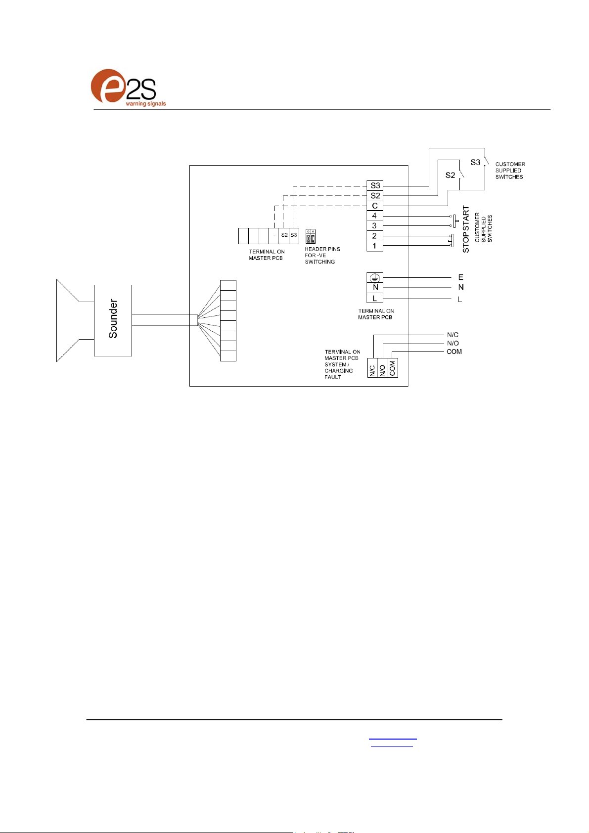
The system comprises of a central control unit
which is configured to drive an audible horns
containing four driver units.
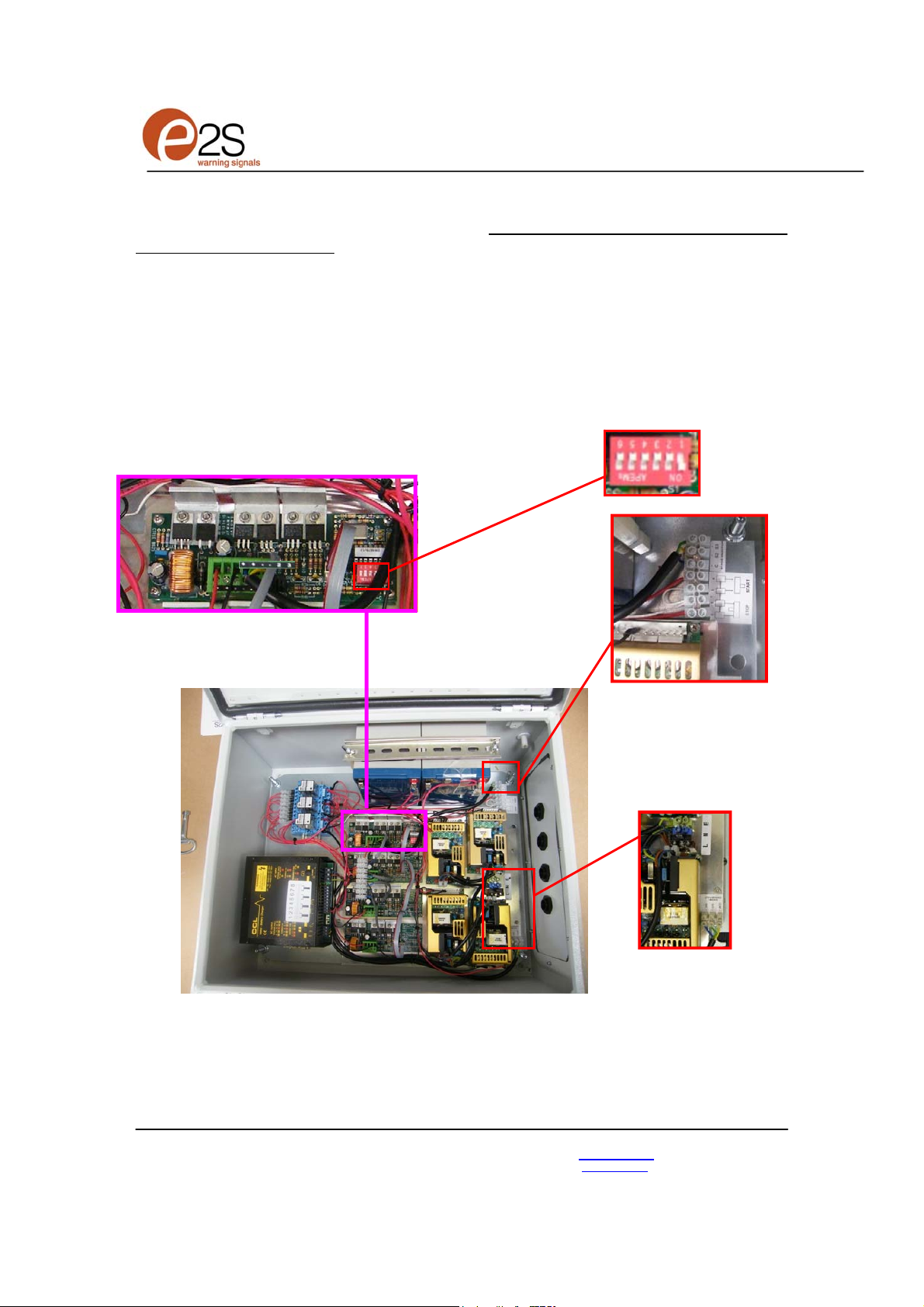
The control unit produces forty five different alarm
sounds (tones) that are selectable using an
internal dipswitch (see tone table page 3 for
available tones) including a stage 2 and stage 3
alarm option.
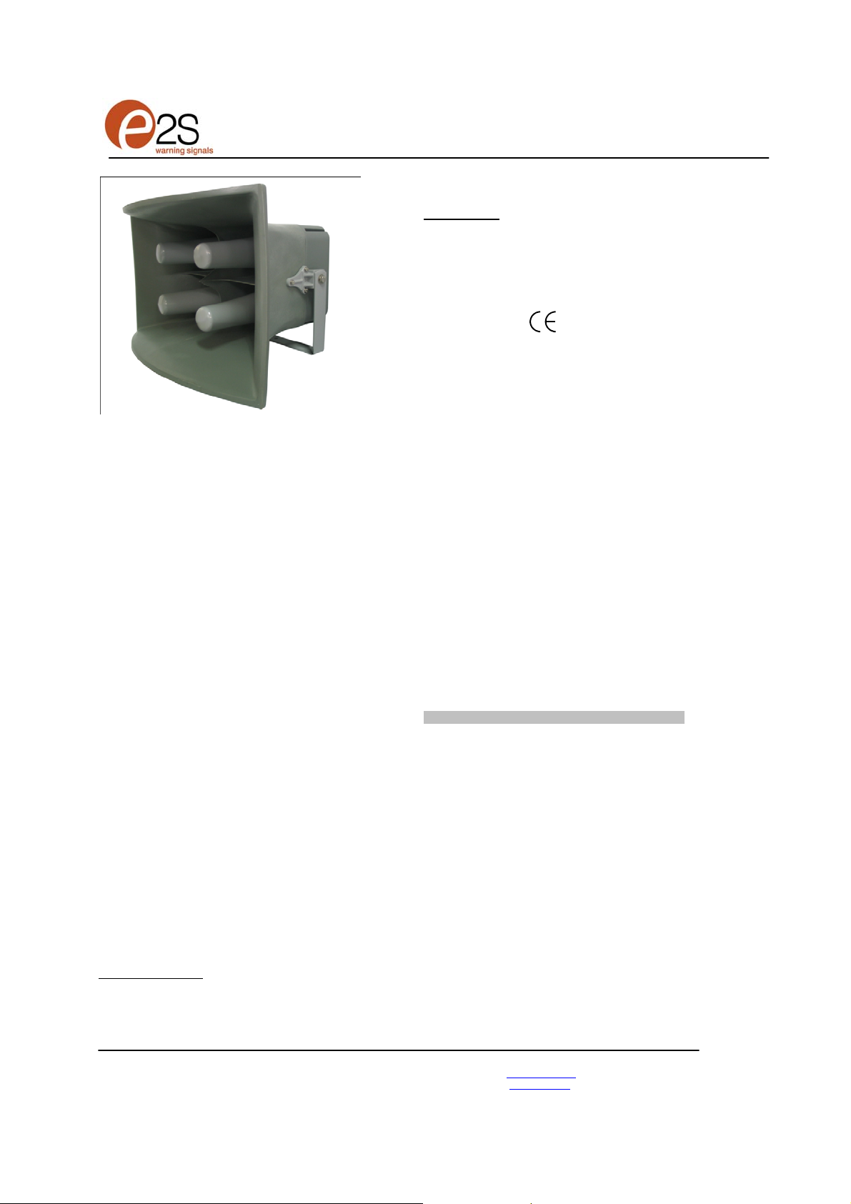
Each audible horn is capable of producing a
range of loud warning signals with output levels
at one meter of approximately 141dB(A)
depending on tone selected.
Both the control unit and horns are suitable to
mount either indoors or outdoors in a number of
mounting configurations with ingress protection to
IP65.
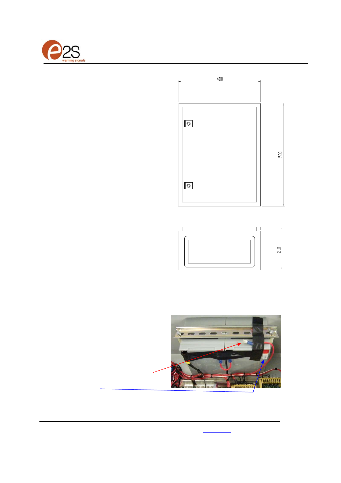
This particular unit is also fitted with a Battery
backup system with fault monitoring with relay
terminals and a set of remote start and stop
terminals.
2) Operating and Marking
All units have the following operating
requirements and limitations.
Audible Horn Units
Unit Type No.: A141
Operating Temp: -20 to +55C
IP Rating: IP65
Horn weight: 14kg
Control Panel
Unit Type No. A141AC230GB
Input Voltage:
115 or 230VAC (90V to 264V AC range)
Operating Temp: -20 to +55C
IP Rating: IP65
Marking:
Control Unit weight : 23kg
3) Installation Requirements
Always de-energize control unit before removing
cover.
The installation of the units must be in
accordance with any local codes that may apply
and should only be carried out by a competent
electrical engineer who has the necessary
training.
3) Power Supply Selection
It is important that a suitable power supply is run
the control unit. The power supply selected must
have the necessary capacity to provide the input
current to the control unit.
The following table shows the input current taken
by the various control unit configurations units:-
AC Unit Type Input Input Range.
No. Horns Voltage Current I/P Volts
A141AC230GB 90-264V AC
115V AC 4.2A
230V AC 1.95A
Table 1: Variants and power requirements
Current levels shown above are for the nominal
input voltage. The input current will vary
according to the voltage input level and the tone
selected.
The above table also shows the maximum and
minimum voltages at which the control units can
be operated.
4) Cable Selection
When selecting the cable size consideration must
be given to the input current that the control unit
draws (see table above) and the length of the
cable run.

INSTRUCTION MANUAL
A141 High Level Audible Warning System / Battery backup
European Safety Systems Ltd.
Impress House, Mansell Road, Acton, London W3 7QH
www.e2s.com Fax: +44 (0)208 740 4200
Document No. D161-00-201-IS_Issue_E 12-02-13
Sheet 2 of 5
5) Earthing
AC powered control units must be connected to a
good quality earth. The unit is provided with
internal earthing terminal which is located next to
the power terminal (See figure 2).
6) Horn Location and Mounting
The location of the horn should be made with due
regard to the area over which the warning signal
must be audible. The horn should only be fixed to
services that can carry the weight of the unit.
The horn should be securely bolted to a suitable
surface using the stainless steel U shaped
mounting bracket. The angle can then be
adjusted in the direction that the sound is
primarily required to cover. This can be achieved
by loosening the two large bracket bolts in the
side of the unit, which allow adjustment. On
completion of the installation the two large
bracket adjustment bolts on the side of the unit
must be fully tightened to ensure that the unit
cannot move in service.
7) Control Unit Location and Mounting
The location of the control unit will depend on the
level of customer accessibility required. The
control unit should only be fixed to services that
can carry the weight of the unit.
Battery checking and maintenance should also
be taken into consideration when selecting a
mounting position. The control unit is mounted via
the cabinets internal mounting positions using 4
off suitable screws.
The overall dimensions of this cabinet are
400mm x 500mm x 210mm, see installation
figure 1-1.
8) Battery Installation
To prevent any problems during transportation,
the system does not have the battery connected.
Once the control unit has been installed the
battery should be connected. The loose red cable
shown should be connected to the battery
terminal 4 as shown.
The battery should be routinely checked to
ensure maximum battery life and correct
charging.
Fig 1-1 Control Unit mounting Installation
Fig 1-2 Battery Installation
1 2 3 4

INSTRUCTION MANUAL
A141 High Level Audible Warning System / Battery backup
European Safety Systems Ltd.
Impress House, Mansell Road, Acton, London W3 7QH
www.e2s.com Fax: +44 (0)208 740 4200
Document No. D161-00-201-IS_Issue_E 12-02-13
Sheet 3 of 5
There is a set of contacts that change over on a
system fault, this includes a battery fault or a
charging fault.
9) Wiring of Control Unit to Power and
horn units
For wiring schematics see figures 3. The control
unit needs to be wired to a suitable power supply
cable supplied by the customer. The power
terminals on the control unit are clearly marked
and will accept up to 2.5mm
2
cable. See figure 2.
The cable from the horn to the control unit is 10m
in length. It should be fed through the cable gland
in the control unit and then wired into the terminal
block provided.
The individual cores are numbered 1 to 8 and
connect the four drivers from the horn to the four
PCBA’s in the control unit in pairs: 1+2, 3+4, 5+6
and 7+8.
The four PCBA’s in the control unit are pre-wired
with an 8 way terminal block to which the 8 core
cable should be connected. The connections
should be made in sequence as shown on the
terminal connection label in the control unit.
10) Tone Selection Table
The A141 high level audible warning system has
45 different tones that can be selected for the first
stage alarm. The systems can then be switched
to sound second and third stage alarm tones. The
tones are selected by operation of a DIP switch in
the control unit.
The tone table below shows the switch positions
for the 45 tones and which tones are available for
the second and third stages.
11) Start Stop Switches
The remote operation of the start and stop
switches is outlined as follows.
The stop switch needs to be of the normally
closed momentary contact type and the start
switch needs to be of the normally open
momentary contact type.
The units is constantly powered to charge the
batteries, the stop switch is normally closed. To
start the unit the normally open start switch is
pressed to momentarily closes to initiate the
sounder. To stop the sounder the normally closed
stop switch is momentarily opened to stop the
unit.
Table 2: Tone selection table

INSTRUCTION MANUAL
A141 High Level Audible Warning System / Battery backup
European Safety Systems Ltd.
Impress House, Mansell Road, Acton, London W3 7QH
sales@e2s.com Tel: +44 (0)208 743 8880
www.e2s.com Fax: +44 (0)208 740 4200
Document No. D161-00-201-IS_Issue_E 12-02-13
Sheet 4 of 5
Terminal for
S2 / S3 / C
connections
Remote start /
stop terminals
Terminal block
for Customer AC
Power input
L = Live
N = Neutral
E = Earth
Charging status
and fault
contacts
Dip switch for
tone selection
(1 0 0 0 0 0 position shown)
12) Remote Sounder Operation
AC Units First Stage Tone Selection
This system is supplied with terminals that allow
the system to be wired and operated using a start
and stop switch in a remote location such as a
control room etc. The terminals for a start and
stop function are shown see figures 2 and 3.
AC Units Second and Third Stage Tone Selection
To select the second and third stage tones on the
A141 audible alarm system, connect to the S2
terminal the switch for the second stage tone,
connect to the S3 terminal the switch for the third
stage tone. Connect both switches together to the
C (common) terminal. See figure 3.
Figure 2 Layout of wiring in control unit
Master control board

INSTRUCTION MANUAL
A141 High Level Audible Warning System / Battery backup
European Safety Systems Ltd.
Impress House, Mansell Road, Acton, London W3 7QH
sales@e2s.com Tel: +44 (0)208 743 8880
www.e2s.com Fax: +44 (0)208 740 4200
Document No. D161-00-201-IS_Issue_E 12-02-13
Sheet 5 of 5
Fig 3: Schematic Circuit Diagram of AC unit with stages S2 and S3 with negative switching
This manual suits for next models
1
Table of contents
Other E2S Safety Equipment manuals
Popular Safety Equipment manuals by other brands

TEUFELBERGER
TEUFELBERGER treeMOTION MANUFACTURER'S INFORMATION AND USER INSTRUCTIONS

nvent
nvent ERICO System 1000 instruction sheet

turck
turck IMXK12-AI01 Series quick start guide

NEW TRIBE
NEW TRIBE Basic Saddle quick start guide

NCR
NCR VOYIX 7772-K040 Kit instructions

Tractel
Tractel guard trac Installation, operating and maintenance manual