CC200 / CC400 General Production Hose Crimper
4
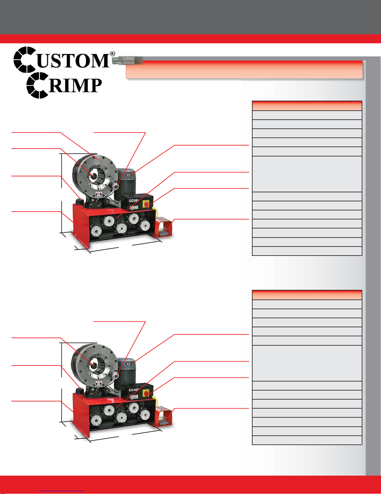
COMPONENT PARTS & TECHNICAL DATA
Notch for clearance
of 90° fittings Metric Micrometer
Style Adjustment
Manual Back Stop
The Foot Switch permits dies
to be “jogged” into position
and keeps both hands free
The 5 HP motor delivers the
power needed to get the job
done quickly
29"
20"
Small Footprint for
minimum use of space
32"
Technical Data
340 Ton
Max 2SP: 2-½", 4SP: 2-½", 6SP: 2-½"
Max Industrial: 3"
L: 20" x W: 29" x H: 32"
Weight: 635 lbs
Power: 5HP / 230V / 3Phase (Standard)
5HP / 440V / 3Phase (Optional)
5HP / 230 / 1Phase (Optional)
1HP / 12VDC (Optional)
1HP / 24VDC (Optional)
Die series: 99S / 130S
Adjustability: Metric
Opening w/o dies: 160mm / 6.30"
Master die inside diameter: 130mm / 5.12"
Master die travel: 38mm / 1.5"
Reservoir capacity: 8 US Gallons
Oil type: ISO 46 Hydraulic Oil
Built-in die storage panel
keeps frequently used die
sets readily available
Power Switch
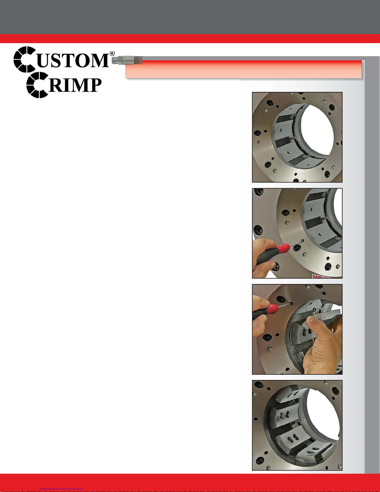
Metric Micrometer
Style Adjustment
Manual Back Stop
CC200 Hydraulic Hose Crimper
CC400 Hydraulic Hose Crimper
The Foot Switch permits dies
to be “jogged” into position
and keeps both hands free
The 5 HP motor delivers the
power needed to get the job
done quickly
29"
20"
Small Footprint for
minimum use of space
32"
Built-in die storage panel
keeps frequently used die
sets readily available
Power Switch
Technical Data
265 Ton
Max 2SP: 2", 4SP: 2", 6SP: 1-½"
Max Industrial: 4"
L: 20" x W: 29" x H: 32"
Weight: 660 lbs
Power: 5HP / 230V / 3Phase (Standard)
5HP / 440V / 3Phase (Optional)
5HP / 230 / 1Phase (Optional)
1HP / 12VDC (Optional)
1HP / 24VDC (Optional)
Die series: 99S / 145S
Adjustability: Metric
Opening w/o dies: 182mm / 7.17"
Master die inside diameter: 145mm / 5.71"
Master die travel: 60mm / 2.4"
Reservoir capacity: 8 US Gallons
Oil type: ISO 46 Hydraulic Oil
Oil Filler Cap
Reservoir
Oil Filler Cap
Reservoir