CustomCrimp D100 SERIES User manual

D100 SERIES HYDRAULIC HOSE
CRIMPER OPERATORS MANUAL

2Page
Revised 08-28-2007
D100P SERIES CRIMPER D100H SERIES CRIMPER
MODELS COVERED
This manual is applicable to different versions of the D_100_ Series Crimpers.
A “Standard”, “Metric” and “DC” micrometer is available on different models.
Crimping, calibration and repair procedures are similar for all models. See
specific instructions and parts breakdown for the model in question
D100S SERIES
CRIMPER
D101S SERIES
CRIMPER
VALPOWER PUMP
(OPTIONAL)

Page 3
COMPONENT PART IDENTIFICATION
MICRO-CRIMP
ADJUSTER
POWER SOURCE
MANUALUNIT
SHOWN
CALIBRATION
ADJUSTMENT
SCREW
REMOVABLE
PUSHER
COMPRESSION
RING
AVAILABLE MICRO-CRIMP MICROMETERS STANDARD
DIE SET DOUBLE ANGLE
DIE SET
STANDARD “DC” METRIC
READ INSTRUCTIONSAND IDENTIFYALL COMPONENT PARTS
BEFORE USING CRIMPER.
CRIMPER CAN PRODUCE 35 TONS OF FORCE. KEEP BOTH HANDS
AWAY FROM PINCH POINTS.
CONSULT HOSE AND FITTING MANUFACTURER FOR
CORRECT MACHINE SETTINGS AND CRIMP MEASUREMENTS.
ALWAYS WEAR EYE PROTECTION.
SAFETY PRECAUTIONS

4Page
D100 SERIES QUICK START GUIDE
TO ASSURE ACCURATE CRIMP DIAMETERS FOLLOW THESE STEPS
BEFORE YOU USE THE CRIMPER FOR THE FIRST TIME
CALIBRATION CHECK PROCEDURE
•Position the crimper on a sturdy surface in a will lighted area
•Check crimper calibration prior to initial operation
•Seat the Pressure Plate (flat plate) in the base of the crimper
•Place any D100 series die set on top of the Pressure Plate making certain
that the die set is firmly seated against the Pressure Plate.
Note: Do Not use Double Angle Die set for
calibration check
•Place the Compression Ring
on top of the die set in the order
shown and slide the pusher onto
the ram.
•Set the Micro-crimp adjuster
as follows:
Standard Micrometer: “100”
“DC” Micrometer: “95”
Metric Micrometer: “0”
•Bring the Pusher into contact
with the Compression Ring and
continue to apply force until the die set is fully
closed and the white line is flush with the surface of
the micro crimp adjuster as shown.
•Note that for the D101S series, the electric switch
will shut off the power source at the point at which
the die set is fully closed and the pump starts to
build pressure.
•If the white line is not just visible as shown or the
pump does not shut off at the point where the die set is fully closed, the
crimper must be recalibrated. See calibration instructions.

Page 5
CALIBRATION INSTRUCTIONS
•Place the Pressure Plate, any D100 Series Standard Die Set and the Compression
Ring in the crimper in the order shown. Do Not use Double Angle Components
•Set the Micro-Crimp Adjuster as follows:
Standard Micrometer: “100”
“DC” Micrometer: “95”
Metric Micrometer: “0”
•Bring the ram and pusher down on top of
the compression cone and increase the
pump pressure until the die set is completely
closed and the pump starts to build
pressure.
All D100 Series Crimpers
•Continue increasing the pressure on the compression Cone
until the circumferential white line on the Micro-Crimp Sight
Button just becomes visible above the Micro-Crimp Adjuster
as shown in the illustration.
D101S Series Crimpers (with electric pump)
•The Electric pump should completely close the die set
before the pump shuts off.
•If the white line is not visible or the electric pump does not
shut off when the dies are completely closed, adjust the
calibration adjustment screw under the Micro-Crimp Adjuster
contact button as illustrated. Repeat the calibration
procedure until the above conditions are satisfied.
•When the above conditions are met, the crimper is
calibrated and ready for use.

6Page
•Place the flat pressure plate in the bottom flange and select the
correct die set for the combination of hose and fitting to be
crimped. Refer to the hose and fitting manufacturer’s
recommendation for the correct die set to use.
•Lubricate the contact surfaces of the die fingers and
compression cone thoroughly with the die lubricant furnished with
the crimper (EZCRIMP M).
Failure to lubricate the contact surfaces with the proper
lubricant will cause the dies to seize in the compression cone.
•Set the Micro-Crimp Adjuster to the setting recommended by the
hose and fitting manufacturer for the combination of hose and
fitting being crimped.
NOTE: The Metric Micro-Crimp Adjuster is a direct reading
micrometer. Add the setting on the micrometer to the closed
diameter of the die set to obtain the finished crimp diameter. For
example: With a 39mm die and the Micro-Crimp Adjuster set at
3 the finished crimp diameter would be 42mm
•Place the Compression Ring over the die set and align the fitting
to the correct position.
•Slowly bring the Pusher in contact with the Compression Ring
until the hose and fitting are held in position with a very light
pressure. Recheck the fitting for correct alignment.
•Continue to apply pressure until the white circumferential line on
the Micro-Crimp Sight Button just appears above the Micro-Crimp
Adjuster (See illustration on P 5) or the electric power unit shuts
off for the 101S crimper.
•Check the diameter of the finished crimp to be certain that it is
within the specifications of the hose and fitting manufacturer.
NOTE: Each die set has a limited range of diameters for
which it can be used. A “Rule of Thumb” is that if you can see
the notches on the die fingers under the Compression Ring
prior to crimping, you must select a larger die size.
CRIMPING WITH STANDARD DIES

Page 7
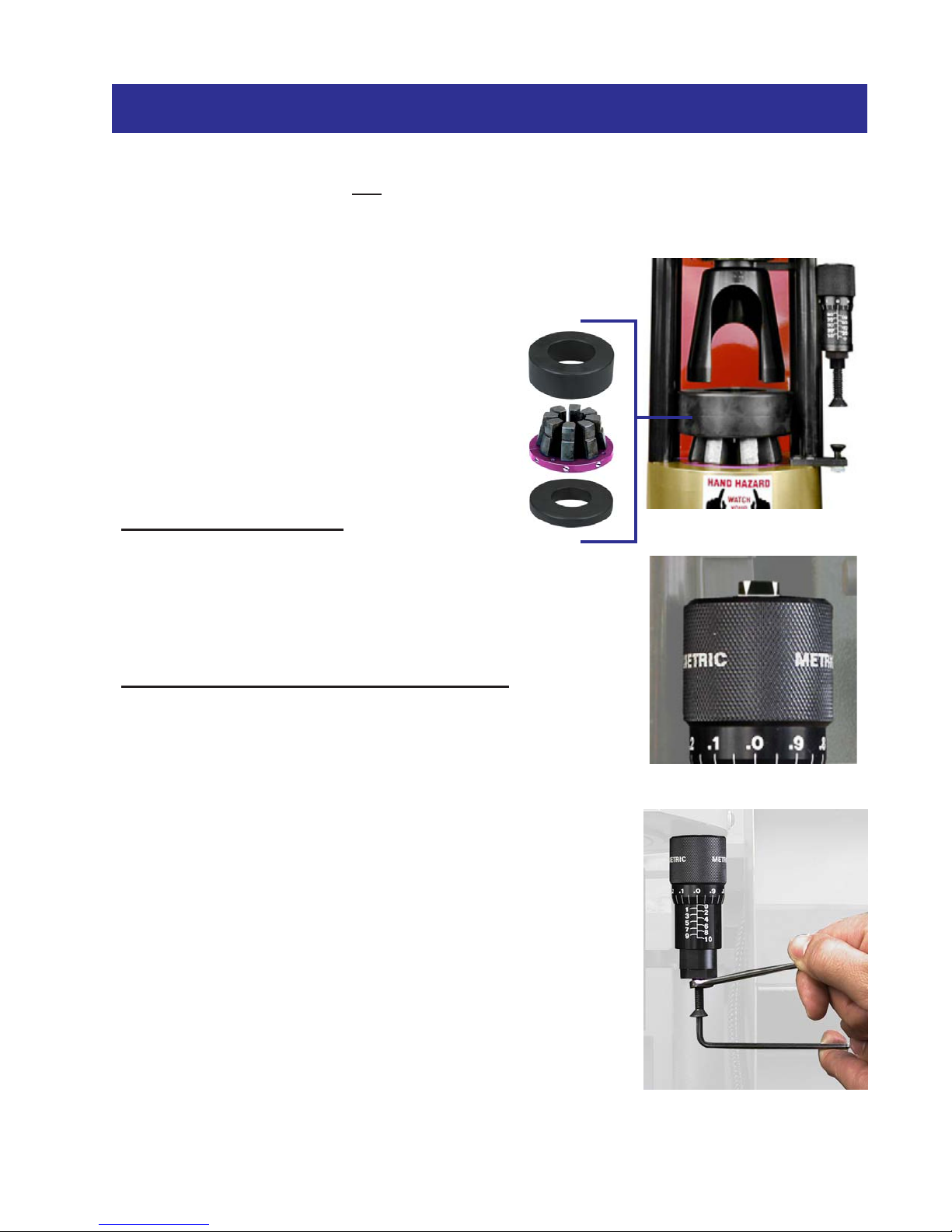
•The Double Angle Dies are special purpose dies designed to
double the crimping force thus allowing larger fittings to be
crimped with less vertical force.
The limitation, however, is that they must crimp to a near
fully closed position and therefore a given die set can crimp
only limited range above the diameter shown on the die ring.
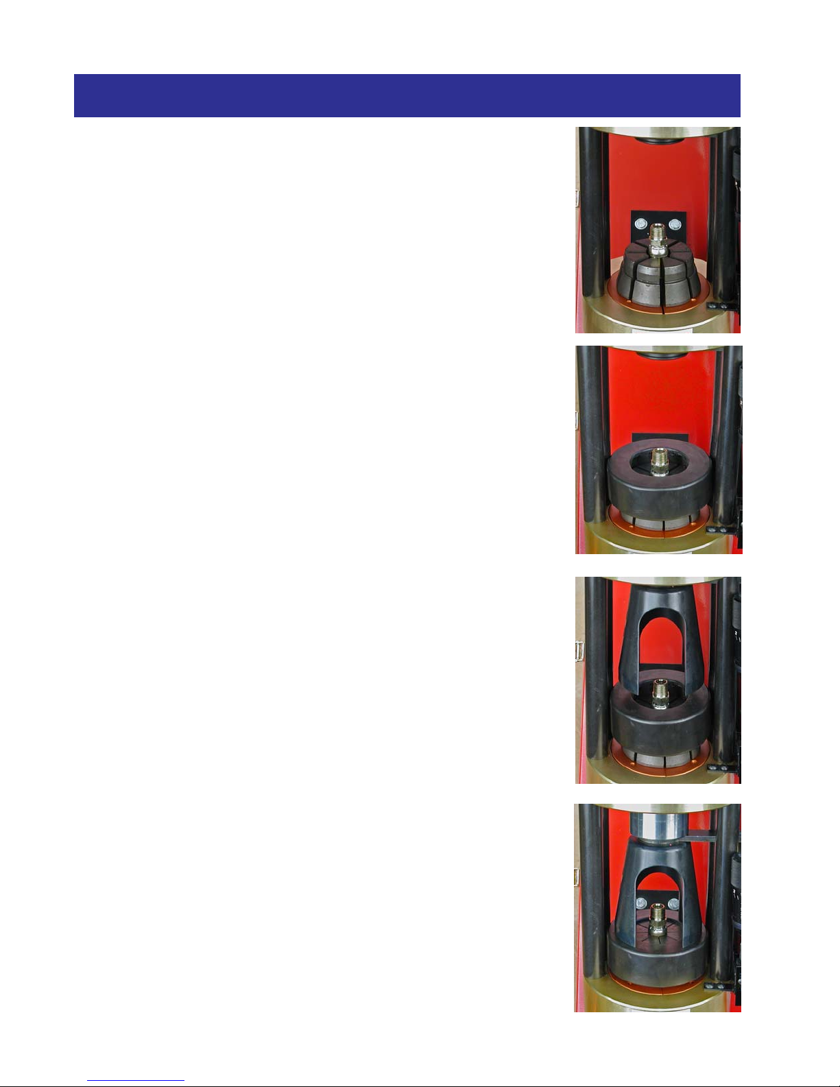
•To use the Double Angle Die set, remove the flat pressure plate
from the cone base and replace it with the compression plate
labeled ‘DBL BASE’ whose angle matches that on the Double
Angle Die.
•Seat the Double Angle Die in the conical recess of the ‘DBL
BASE’ cone and position the hose and fitting as specified by the
fitting manufacturer.
•Place the ‘DBL TOP’ Compression Ring on top of the die set
making sure that the fitting is still correctly positioned. Slide the
pusher into place on the cylinder ram.
Note: the angles on the Double Angle compression ring and
the Standard Compression ring are not the same. The DBL
Top compression ring must be used with the Double Angle Die
set.
•Set the Micro-Crimp Adjuster at the recommended setting
specified by the hose and fitting manufacturer.
Note: The direct reading feature of the Micro-Crimp Adjuster is
not applicable with Double Angle Dies. Follow the hose and
fitting manufacturer’s recommendations
•Cycle the crimper until the white circumferential line on the
Micro-Crimp Sight Button just appears on the top of the Micro-
Crimp Adjuster or the power unit shuts off for the D101S unit.
Note that if the die is not brought to a near fully closed condition,
there is the possibility that the crimps will be tapered along the
length of the crimp diameter.
•Check the crimp diameter to be certain that it is within the specifications of the hose and
fitting manufacturer.
CRIMPING WITH A DOUBLE ANGLE DIE

8Page
COMPONENT IDENTIFICATION

Page 9
COMPONENT IDENTIFICATION

10Page
COMPONENT IDENTIFICATION

Page 11
COMPONENT IDENTIFICATION
1
2
3
4
5
35-Ton Head Sub-Assembly (101209)
QTYDESCRIPTIONPART NUMBERITEM
1
35-Ton Cylinder/Flange
1031221
4Strain Rod - 8 1/2"1003292
1Bottom Flange1003253
4
3/4 Flat Washer - Special750SPCL
4
43/4-10 Hex Nut95462A538
5

12Page
COMPONENT IDENTIFICATION
35 Ton Cylinder / Flange Assembly (103122)
QTYDESCRIPTION
PART NUMBERITEM
1
Cylinder Body
1025111
1Cylinder Piston1015152
1
030 Disogrin O-Ring
030D903
1Cylinder Piston Cap100689
4
8
1/4-20 X 3/4 SHCS
91251A540
5
1Cylinder Spring1012826
1
Spring Plug
1015167
1210 Disogrin O-Ring210D908
1
T-Seal
TP0329
1Ram WiperSH959-2610
1
Cylinder Retaining Ring
10151411
15/16 Flat Washer90108A41512
1
5/16-18 x 1.50 HHCS
92865A58713
13
12
1
9
2
6
3
4
10
11
7
8
5
Other manuals for D100 SERIES
1
This manual suits for next models
4
Table of contents
Other CustomCrimp Power Tools manuals