CustomCrimp SM 300 User manual

SM 300 / SM 300M
HOSE SKIVING TOOL MANUAL
The SM 300 Hose Skiver can be either bench
mounted or mounted on its own SM300 Mobile Cart.

2
SAFETY PRECAUTIONS
READ INSTRUCTIONS AND IDENTIFY ALL COMPONENT PARTS BEFORE
USING THE SM300 HOSE SKIVER.
KEEP HANDS AND LOOSE CLOTHING AWAY FROM CUTTING INSERTS.
SAFETY GUARD SHOULD ALWAYS BE USED WHEN SKIVING A HOSE.
SAFETY GUARD SHOULD NEVER BE REMOVED.
CONSULT HOSE AND FITTING MANUFACTURER’S SPECIFICATIONS FOR
CORRECT SKIVE MEASUREMENTS.
ALWAYS WEAR EYE PROTECTION AND APPROPRIATE PROTECTIVE GEAR.
SM 300M / SM 300 HOSE SKIVER COMPONENT PARTS IDENTIFICATION...............................................3
AVAILABLE ACCESSORIES...........................................................................................................................4
SM 300 HOSE SKIVER SPECIFICATIONS AND INITIAL SETUP...................................................................5
SM 300 HOSE SKIVER OD TOOLING FEATURES.........................................................................................6
WORKING WITH OD TOOLING.......................................................................................................................7
WORKING WITH ID TOOLING.......................................................................................................................10
EXPLODED PARTS VIEW.............................................................................................................................12
INDEX
NOTE
The instructions for working with OD Tooling and ID Tooling can be used
when using the SM 300M (Hand Operated Skiving Tool).

3
110 Volt 15 Amp Power
Source Required.
Main Power Switch
Safety Switch
1/3 HP Single Phase Motor
Discharge / Waste
OD Skiving Tool ID Skiving Tool
SM300 Tool Holder
(Optional)
SM300 Mobile Cart
(Optional)
(2) Lockable
Swivel Casters
Safety Shield which lifts
easily for tool and insert
changes
PTO Coupling for
quick tool change
Reversing Switch for
ID and OD Skiving
Foot Switch for
hands free operation
110 Volt 15 Am
p
Power
S
ource Require
d.
er
S
witc
h
1
/
3 HP
S
i
n
Dischar
g
e
o
l Holder
S
M
300
M
o
(O
ptional
)
e
t
ers
w
itch
f
or
S
kivin
g
Foot
S
witch
f
or
h
ands
f
ree operatio
n
SM 300M / SM 300 HOSE SKIVER COMPONENT PART IDENTIFICATION
Fuse
14-⅜"
PTO Coupling for
quick tool change
Heavy duty vice
mounting bracket
Handle
ou t g b ac et
Electric Hose Skiver Unit
P/N:SM 300
Shown with optional accessories.
Hand Operated Skiving Tool
P/N:SM 300M

4
Hose
Size
OD Skiving Tool
Assembly P/N:
04 103692-04
06 103692-06
08 103692-08
10 103692-10
12 103692-12
16 103692-16
20 103692-20
24 103692-24
32 103692-32
40 103692-40
48 103692-48
Hose
Size
ID Skiving Tool
Assembly P/N:
04 104028-04
06 104028-06
08 104028-08
10 104028-10
12 104028-12
16 104028-16
20 104028-20
24 104028-24
32 104028-32
40 104028-40
48 104028-48
AVAILABLE ACCESSORIES
Hand Operated Hose Skiver Tool
P/N:SM 300M
SM300 Tool Holder
P/N:104247
SM300 Mobile Cart
P/N:101956
OD Carbide Skiving
Insert P/N:103993
OD Skiving Insert Screw
P/N:103994
ID Skiving Steel Blade
P/N:104141

5
SM 300M SPECIFICATIONS:
HOSE CAPACITY ----------------------------------------------------------1/2 INCH TO 3 INCH ID AND OD (-04 THRU -48)
SKIVER SIZE --------------------------------------------------------------------------------------------14-⅜" LONG
WEIGHT --------------------------------------------------------------------------------------------------------------10 LBS
SM 300 SPECIFICATIONS:
POWER REQUIREMENTS-----------------------------------------------------------------110 V 15 AMP 60 HZ SERVICE
HOSE CAPACITY ----------------------------------------------------------1/2 INCH TO 3 INCH ID AND OD (-04 THRU -48)
SKIVER SIZE W/O OPTIONAL MOBILE CART ---------------------------------------------------L:29" X W:25" X H:21"
SKIVER SIZE W/ OPTIONAL MOBILE CART ---------------------------------------------------L:30” X W:29” X H:49”
WEIGHT -----------------------------------------------------------------------------------150 LBS W/O OPTIONAL CART
-------------------------------------------------------------------------------------------175 LBS W/ OPTIONAL CART
GEAR MOTOR SPECIFICATIONS ------------------------------------------------1/3 HP, 59 RPM, 330 IN LB TORQUE
If you received the bench top model, make certain that it is securely
bolted to the bench top and/or stand as considerable torque is
generated when skiving some of the larger hoses.
If you using the SM300 Mobile Cart make certain that the wheel
lock’s are securely locked in place while you are skiving.
SM300 Tool Holder shown below, is available separately to keep
skiving tools organized and readily available. It can be mounted
below the skiver on the SM300 Mobile Cart as shown or bench
mounted in a location of your choice.
SM 300M / SM 300 HOSE SKIVER SPECIFICATIONS
SM 300 INITIAL SETUP

6
SM 300 HOSE SKIVER OD TOOLING FEATURES
The SM 300 Hose Skiver has the capacity and available tooling to
skive 2, 4, and 6 wire hoses from 1/2 inch thru 3 inches.
OD tools use readily available carbide cutting inserts. Carbide inserts
not only wear longer than conventional steel cutting tools, but they
never need sharpening. If an insert becomes dull, simply rotate it to
another cutting surface or install a new insert.
Note: No readjustment of the cutting tool is required.
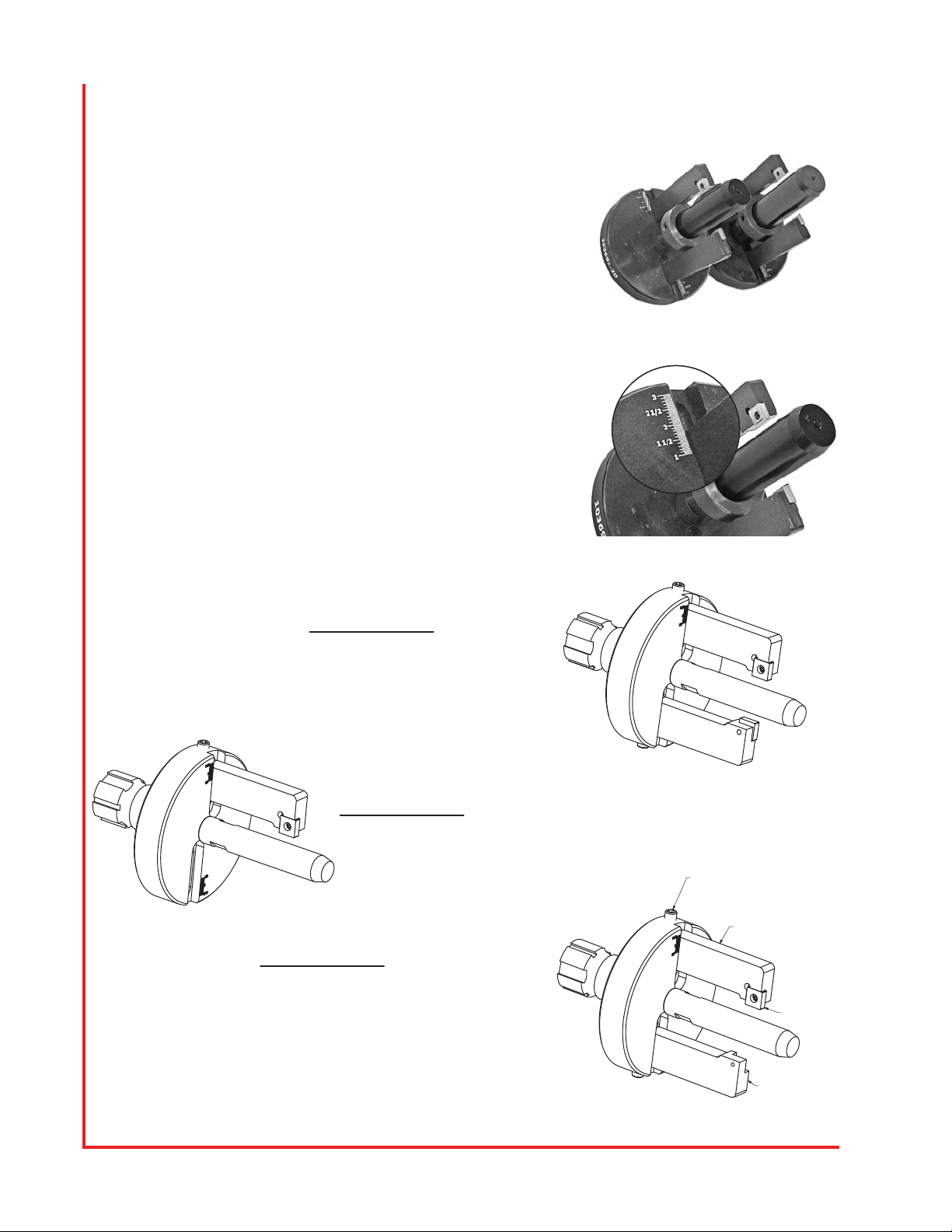
The OD Skiving Tool is designed with two cutting arms. Both can be
adjusted to skive a single hose, but the real advantage of the two
arms is that one arm can be adjusted to skive diff erent wire hose.
For example: To switch from 2 wire skiving to 4 wire skiving, simply
remove the insert from the arm adjusted for 2 wire. The set up options
are shown in the panel below.
Tip: While the guide lines etched on the face of the OD Skiving Tool
will be very close to the correct setting, fine adjustment can be made
by leaving the hex bolt on the back face of the tool slightly loose and
adjusting the set screw on the edge of the tool before finally tightening
the hex bolt on the back face of the tool.
OPTION #1
Both Insert Arms can be set to the same
diameter on the etched scale and both
arms will work together.
OPTION #2
Only one Insert Arm may be installed and dialed
to the correct diameter on the etched scale.
OPTION #3
One Insert Arm can be dialed to skive a 4 spiral
hose and the other Insert Arm can be dialed to a
6 spiral hose of the same size.
If a 4 spiral hose is being skived, remove the 6
spiral Skiving Insert. If a 6 spiral hose is being
skived, remove the 4 spiral Skiving Insert.
SET UP FOR A 6 SPIRAL HOSE.
SET UP FOR A 4 SPIRAL HOSE.
SKIVING INSERT
5/16-18 Set Screw

7
HOW TO REMOVE THE OD TOOLING
1. Lift the safety guard out of the way.
2. Slide the PTO quick coupling back to release it.
3. Place the OD tool back into holder.
HOW TO ADJUST THE OD TOOLING SKIVE LENGTH
1. Verify the skive depth in the hose and fi tting manufacturer’s
literature.
2. Loosen the depth collar screw (as shown).
3. Lock the calipers to the desired OD skive length.
4. Place the calipers (as shown) to hit the front edge of skiving
insert and the depth collar at the same time.
5. Tighten the depth collar screw.
6. Skive hose and verity that the depth matches the hose and
fi tting manufacturer’s specifi cations.
HOW TO LOAD THE OD TOOLING
1. Lift the safety guard out of the way.
2. Select the proper OD tool and verify that adjustment arms
are set to proper depth.
3. Push the PTO quick coupling (as shown) back, align grooves
on OD tool and insert until PTO snaps into place.
4. Put safety guard back into position.
Skive length

8
HOW TO ADJUST SKIVING DEPTHS ON OD TOOL
1. Place the hose on to mandrel and slide the hose up to the
cutting inserts.
2. Loosen the 3/8-16 hex head bolt with a 9/16" wrench.
3. Slide the adjustment bars to a position just above hose wires
(as shown).
4. Tighten the 3/8-16 hex head bolt with a 9/16" wrench.
5. Skive the OD of a hose to check how close to the wire you are.
6. To make a small adjustment loosen the hex head bolt again
and use the set screw (as shown) for minor adjustments.
Note: The scale can be used for reference.
Note: Moving the set screw in will remove more rubber.
Note: Moving the set screw out will remove less rubber.
7. Continue to make adjustment until skive meets the hose and
fi tting manufacturer’s requirements.
8. Make sure that all set screws and hex head bolts are tight.
HOW TO SETUP MULTIPLE SKIVING DEPTH ON
OD TOOL
Note: This is if the same tool will be used to skive different
wire hoses on the same size hose.
1. Follow the initial OD skiving tool setup to set up each adjustment
arm.
For example: -4 wire hose, and the other adjustment arm for
-6 wire hose (as shown).
2. When skiving the larger wire hose remove the smaller wire
cutting insert (as shown).
3. Place the smaller OD insert in when needed.
-4
-6

9
HOW TO CHANGE THE OD SKIVING INSERT
1. Use the insert removable tool that was provided to loosen t h e
screw.
2. Remove the cutting insert.
3. Rotate the cutting insert 90° and lock screw into place.
Note: OD skiving inserts should be replaced when a chip or
other damage occurs or as need.
• Each insert can be used 4 times (4 sides).

1 0
HOW TO LOAD THE ID TOOLING
1. Lift the safety guard out of the way.
2. Select the proper ID tool.
3. Push the PTO quick coupling (as shown) back, align grooves
on ID tool and insert until PTO snaps into place.
4. Put safety guard back into position.
HOW TO REMOVE THE ID TOOLING
1. Lift the safety guard out of the way.
2. Slide the PTO quick coupling back to release it.
3. Place the ID tool back into holder.
HOW TO ADJUST THE ID TOOLING SKIVE LENGTH
1. Verify the skive depth in the hose and fi tting manufacturer’s
literature.
2. Loosen the depth collar screw (as shown in picture).
3. Lock the calipers to the desired ID skive length.
4. Place the calipers (as shown) to hit the front edge of skiving
insert and the depth collar at the same time.
5. Tighten the depth collar screw.
6. Skive hose and verity that the depth matches the hose and
fi tting manufacturer’s specifi cations.
Skive length

11
HOW TO ADJUST SKIVING DEPTHS ON ID TOOL
1. Place the hose on to mandrel and slide the hose up to the
cutting insert.
2. Loosen the set screw that locks insert into place (as shown).
3. Adjust the depth set screw to inner diameter wire.
4. Skive the ID of a hose to check how close to the wire you are.
5. To make a small adjustment continue to adjust the depth of
insert to hose and fi tting manufacturer’s requirements.
6. Make sure that all set screws are tight.

1 2
EXPLODED PARTS VIEW
HAS -08 THRU -16 OD SKIVING TOOL ASSEMBLY (104123)
QTYDESCRIPTION
PART NUMBERITEM
1HAS OD UNIVERSAL CONNECTOR1041221
1
HAS -08 THRU -16 OD BASE PLATE
1041982
11/2'' HOSE ALIGNMENT STUD103691-083
15/8'' HOSE ALIGNMENT STUD103691-104
1
3/4'' HOSE ALIGNMENT STUD
103691-125
1
1'' HOSE ALIGNMENT STUD
103691-166
2HAS-200 DEPTH ADJUSTMENT BAR103749-S
7
2
HAS-200 SKIVING TOOL INSERT
1039938
2
INSERT SCREW
1039949
25/16-18 SET SCREW91375A57410
1
1/2'' BACKSTOP COLLAR
9414T1111
1
5/8'' BACKSTOP COLLAR
9414T1312
13/4'' BACKSTOP COLLAR9414T1513
11'' BACKSTOP COLLAR9414T1914
2
3/8-16 X 1'' HHS
91309A62415
23/8 LOCK WASHER91102A76016
OD SKIVING TOOL PART NUMBERS
PART NUMBER DESCRIPTION
103692-08 1/2" OD SKIVING TOOL ASSEMBLY
103692-10 5/8" OD SKIVING TOOL ASSEMBLY
103692-12 3/4" OD SKIVING TOOL ASSEMBLY
103692-16 1" OD SKIVING TOOL ASSEMBLY
2
1
6543
7
9
8
10
14131211
16
15

13
EXPLODED PARTS VIEW
HAS -20 THRU -32 OD SKIVING TOOL ASSEMBLY (103692)
QTYDESCRIPTIONPART NUMBERITEM
1HAS OD UNIVERSAL CONNECTOR1041221
1
HAS -20 THRU -32 OD BASE PLATE
1041992
11 1/4'' HOSE ALIGNMENT STUD103691-203
11 1/2'' HOSE ALIGNMENT STUD103691-244
1
2'' HOSE ALIGNMENT STUD
103691-325
2SM 300 DEPTH ADJUSTMENT BAR103749-M6
2SM 300 SKIVING TOOL INSERT103993
7
2
INSERT SCREW
1039948
25/16-18 X 1/2'' SET SCREW91375A5749
23/8 LOCK WASHER91102A76010
2
3/8-16 X 1'' HHS
91309A62411
11 1/4'' BACKSTOP COLLAR9414T2412
11 1/2'' BACKSTOP COLLAR9414T2813
1
2'' BACKSTOP COLLAR
9414T3714
1
2
9
543
6
7
8
OD SKIVING TOOL PART NUMBERS
PART NUMBER DESCRIPTION
103692-20 1-1/4" OD SKIVING TOOL ASSEMBLY
103692-24 1-1/2" OD SKIVING TOOL ASSEMBLY
103692-32 2" OD SKIVING TOOL ASSEMBLY
141312
10
11

1 4
EXPLODED PARTS VIEW
HAS -36 THRU -48 OD SKIVING TOOL ASSEMBLY (104123-48)
QTYDESCRIPTION
PART NUMBERITEM
1
HAS OD 3'' UNIVERSAL CONNECTOR
104122-31
1HAS -36 THRU -48 BASE PLATE1042022
1
2 1/2'' HOSE ALIGNMENT STUD
103691-403
1
3'' HOSE ALIGNMENT STUD
103691-484
2HAS DEPTH ADJUSTMENT BAR103749-L
5
2
SKIVING TOOL INSERT
1039936
2
INSERT SCREW
1039947
25/16 SET SCREW91375A5748
23/8 LOCK WASHER91102A7609
1
8
2
3 4
5
6
7
OD SKIVING TOOL PART NUMBER
PART NUMBER DESCRIPTION
103692-40 2 1/2'' OD SKIVING TOOL ASSEMBLY
103692-48 3'' OD SKIVING TOOL ASSEMBLY
11 12
9
10
HAS -36 THRU -48 OD SKIVING TOOL ASSEMBLY (104123-48)
QTYDESCRIPTION
PART NUMBERITEM
1
HAS OD 3'' UNIVERSAL CONNECTOR
104122-31
1HAS -36 THRU -48 BASE PLATE1042022
1
2 1/2'' HOSE ALIGNMENT STUD
103691-403
1
3'' HOSE ALIGNMENT STUD
103691-484
2HAS DEPTH ADJUSTMENT BAR103749-L
5
2
SKIVING TOOL INSERT
1039936
2
INSERT SCREW
1039947
25/16 SET SCREW91375A5748
23/8 LOCK WASHER91102A7609
2
3/8-16 X 1'' HHS
91309A62410
12 1/2'' BACKSTOP COLLAR9414T4511
13'' BACKSTOP COLLAR9414T5212
OD SKIVING TOOL PART NUMBER
PART NUMBER DESCRIPTION
103692-40 2 1/2'' OD SKIVING TOOL ASSEMBLY
103692-48 3'' OD SKIVING TOOL ASSEMBLY

15
EXPLODED PARTS VIEW
SM 300 ID SKIVE TOOL ASSEMBLY (104028-MAN)
QTYDESCRIPTION
PART NUMBERITEM
1
ID SKIVING TOOL BODY104028-HOSE SIZE
1
1-16 TO -32 ID SKIVING BIT1045172
1-08 TO -12 ID SKIVING BIT1045183
1
HAS ID UNIVERSAL CONNECTOR
1042164
24-40 X .187 SET SCREW91375A105
5
14-40 X VARYING LENGTH SET SCREW91375A6
1
1/2-13 LEFT HAND THREAD ROD
95625A3067
1ADJUSTABLE BACKSTOP6436K8
32
8
4
7
1
5
6

1 6
SM 300 ELECTRICAL ASSEMBLY (104057-MAN-1)
QTYDESCRIPTION
PART NUMBERITEM
1BASE ASSEMBLY1036201
1ELECTRICAL ACCESS PANEL1036282
1
MOTOR DRUM SWITCH
1040433
131/2 NPT DOME CORD GRIP103800
4
1110V FOOT PEDAL104046
5
4
10-24 X 1/2 BHCS
91255A2426
1DISCONNECT SWITCH104045
7
1FUSEHOLDER342838 8
1
5
7
6
8
3
4
2
EXPLODED PARTS VIEW

17
EXPLODED PARTS VIEW
SM 300 MOTOR ASSEMBLY (104057-MAN-2)
QTYDESCRIPTIONPART NUMBERITEM
1
HAS-200 MOTOR MOUNT ASSEMBLY
1036221
1HAS-200 300V SAFETY LIMIT SWITCH1040532
1HAS-200 FHP AC GEARMOTOR1040443
1
POLYCARBONATE DOOR
1038734
1
HAS-200 SAFETY DOOR HINGE
1040565
45/16-18 X 1 1/4'' BHCS91255A5856
12
5/16 FLAT WASHER
98023A0307
6
5/16 LOCK WASHER
91102A7558
45/16-18 JAM NUT94895A0309
43/8-16 X 1 1/4'' BHCS91255A62610
8
3/8 FLAT WASHER
98023A03111
210-24 X 1 1/4 SHCS90044A11412
610-24 MACHINE NUT90480A01113
4
10-24 X 1/2 SHCS
91251A24214
2
13
12
3
98
7
7
61
10
11
4
5
14

1 8
CustomCrimp “No-Nonsense” Warranty Statement
All CustomCrimp Products are warranted to be free of defects in workmanship and materials
for one year from the date of installation. This warranty ends when the product becomes
unusable for reasons other than defects in workmanship or material.
Any CustomCrimp Product proven to be defective in workmanship or material will be repaired
or replaced at no charge. To obtain benefi ts of this warranty, fi rst, contact Warranty Repair
Department at Custom Machining Services at (219) 462-6128 and then deliver via prepaid
transportation the complete hydraulic product to:
ATTN: WARRANTY REPAIR DEPT.
Custom Machining Services, Inc.
326 North Co. Rd 400 East
Valparaiso IN 46383
If any product or part manufactured by CustomCrimp is found to be defective by CustomCrimp,
at its option, CustomCrimp will either repair or replace the defective part or product and return
via ground transportation, freight prepaid. Custom Crimp will not cover any incoming or
outgoing freight charges for machines sold outside The United States.
This warranty does not cover any product or part which is worn out, abused, altered, used for
a purpose other than for which it was intended, or used in a manner which was inconsistent
with any instructions regarding its use.
Electric motors are separately warranted by their manufacturer under the conditions stated
in their separate warranty.
SM 300 ELECTRIC HOSE SKIVER UNIT WARRANTY

See the complete line of CustomCrimp® Crimpers and Accessories at:
(219) 462-6128CustomCrimp® www.customcrimp.com
Custom Crimp®
Custom Machining Services, Inc.
326 N. County Rd. 400 East
Valparaiso, IN 46383
Ph: (219) 462-6128
Fax: (219) 464-2773
www.customcrimp.com
This manual suits for next models
1
Table of contents
Other CustomCrimp Power Tools manuals