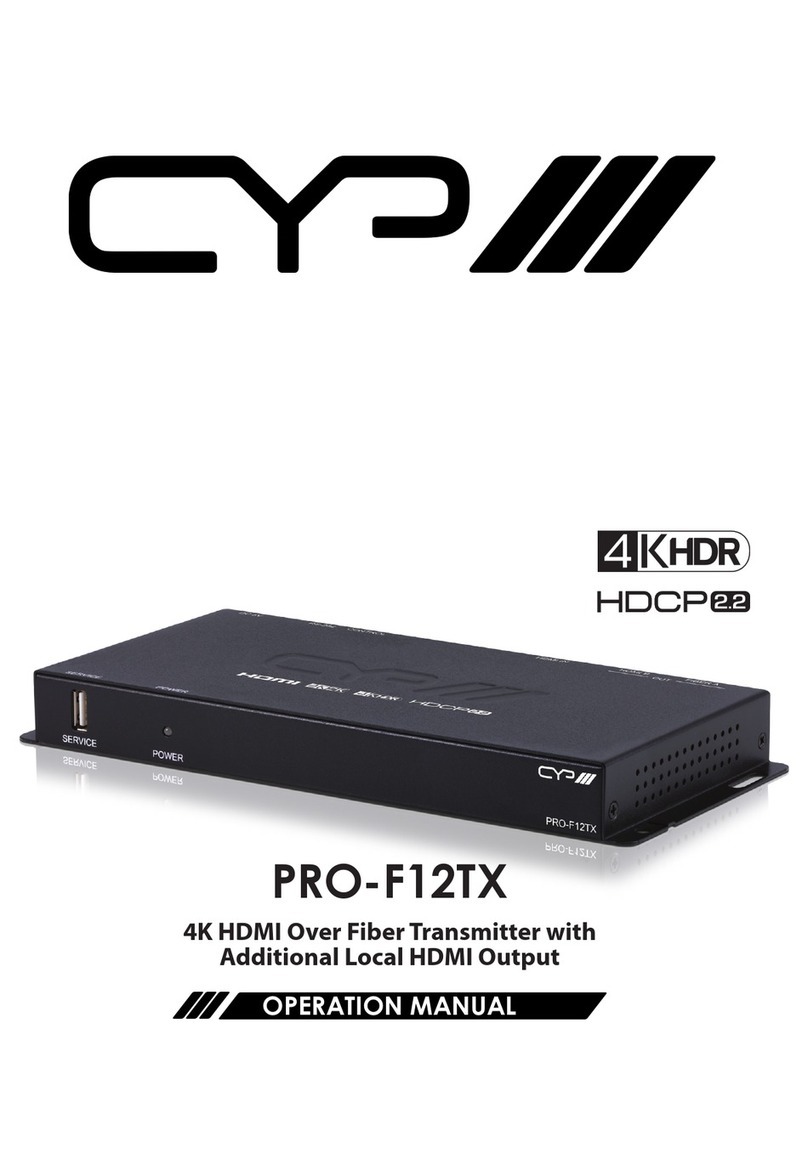
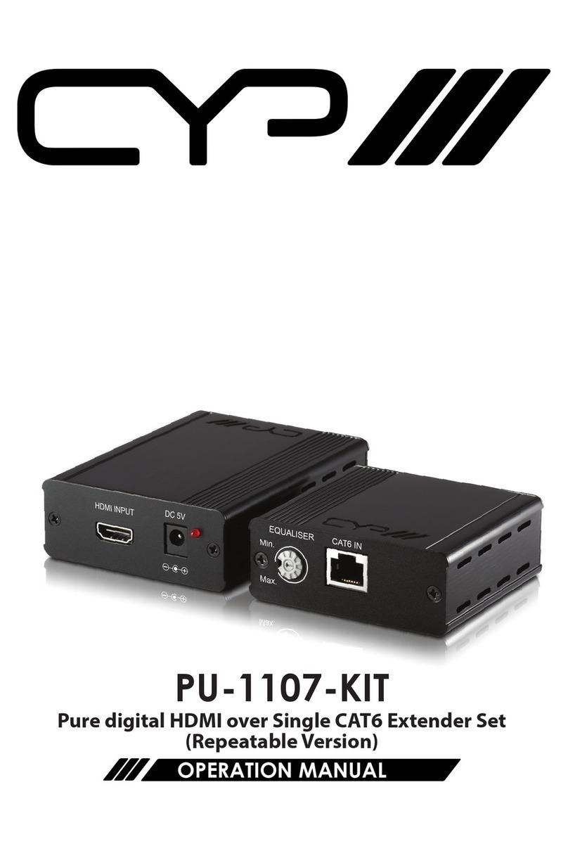
CYP PU-USBX User manual

PU-USBX
USB 2.0 over Ethernet Extender
OPERATION MANUAL


3
DISCLAIMERS
The information in this manual has been carefully checked and is
believed to be accurate. CYP (UK) Ltd assumes no responsibility for any
infringements of patents or other rights of third parties which may result
from its use.
CYP (UK) Ltd assumes no responsibility for any inaccuracies that may be
contained in this document. CYP (UK) Ltd also makes no commitment to
update or to keep current the information contained in this document.
CYP (UK) Ltd reserves the right to make improvements to this document
and/or product at any time and without notice.
COPYRIGHT NOTICE
No part of this document may be reproduced, transmitted, transcribed,
stored in a retrieval system, or any of its part translated into any language
or computer le, in any form or by any means—electronic, mechanical,
magnetic, optical, chemical, manual, or otherwise—without express
written permission and consent from CYP (UK) Ltd.
© Copyright 2011 by CYP (UK) Ltd.
All Rights Reserved.
Version 1.1 August 2011
TRADEMARK ACKNOWLEDGMENTS
All products or service names mentioned in this document may be
trademarks of the companies with which they are associated.

4
SAFETY PRECAUTIONS
Please read all instructions before attempting to unpack, install or operate
this equipment and before connecting the power supply.
Please keep the following in mind as you unpack and install this
equipment:
• Always follow basic safety precautions to reduce the risk of re,
electrical shock and injury to persons.
• To prevent re or shock hazard, do not expose the unit to rain,
moisture or install this product near water.
• Never spill liquid of any kind on or into this product.
• Never push an object of any kind into this product through any
openings or empty slots in the unit, as you may damage parts inside
the unit.
• Do not attach the power supply cabling to building surfaces.
• Use only the supplied power supply unit (PSU). Do not use the PSU if
it is damaged.
• Do not allow anything to rest on the power cabling or allow any
weight to be placed upon it or any person walk on it.
• To protect the unit from overheating, do not block any vents or
openings in the unit housing that provide ventilation and allow for
sucient space for air to circulate around the unit.
REVISION HISTORY
VERSION NO. DATE SUMMARY OF CHANGE
v1.01 25/07/14 Updated format/diagrams
Added 64-bit support

5
CONTENTS
1. Introduction...........................................6
2. Applications ...........................................6
3. Package Contents ..................................6
4. System Requirements ...........................6
5. Features..................................................7
6. Operation Controls and Functions.......8
6.1 Front Panel................................................... 8
6.2 Rear Panel..................................................... 9
6.3 Driver Installation....................................10
6.4 Driver Uninstallation ..............................12
7. Connection Diagram .......................... 13
8. Specications...................................... 14
9. Acronyms............................................. 14

6
1. INTRODUCTION
The PU-USBX USB over Ethernet Extender is allows you to extend up
to four USB devices over an existing LAN network (100m) or direct
connection via a USB cable. Acting as a USB hub, this extender will allow
four USB devices to be connected to your PC using a single USB port.
2. APPLICATIONS
Share USB devices over a network
Meeting room USB control of remote PCs
Transfer of USB data over a network
External USB hub
USB display control (with USB to HDMI converter)
3. PACKAGE CONTENTS
USB over Ethernet Extender
Software CD-ROM (includes Drivers)
5 V/2.6 A Power Adaptor
Operation Manual
4. SYSTEM REQUIREMENTS
PC/laptop with USB or RJ45 cable (direct connection or through an
existing network) and USB devices such as printers, scanners, ash
drives, HDD and digital cameras.
Computer System Requirements: 2.4GHz single core CPU with at least
1GB RAM for optimal performance
Operating Systems:
-Windows XP Home or Professional SP2 (32-bit)
-Windows Vista (32-bit & 64-bit)
-Window 7 (32-bit & 64-bit)

7
5. FEATURES
Control up to 4 four USB devices
Supports high-speed (480 Mbps), full-speed (12 Mbps) and low-
speed(1.5 Mbps) transaction (speed in the LAN Mode might be limited
by the bandwidth of the network)
Works up to 100m away (in the Extender Mode)
Connect with existing Ethernet cable or directly to a PC with RJ-45 cable
Compliant with USB 2.0 (Hi-speed) specication
Support Ethernet protocols TCP/IP
Supports 10/100/1000 Mbps Ethernet speed
Supports Windows XP (SP2), Vista (32/64-Bit), & 7 (32/64-bit)

8
6. OPERATION CONTROLS AND FUNCTIONS
6.1 Front Panel
1 2 3 4 5
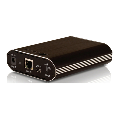
1DC 5V: Plug the 5V DC power supply included in the package into the
unit and connect the adaptor to AC wall outlet.
2Power LED: LED will illuminate green when the device is connected
to a power supply.
3LAN IN: Connect with a RJ45 terminated CAT5e/6 cable to your
existing network system or directly to a PC or laptop.
4USB IN: Connect with a mini-USB to USB cable from your PC/laptop.
5INPUT switch: Switches the input mode between LAN (network) and
direct USB Connection

9
6.2 Rear Panel
1
1USB 1~4: Use to connect to USB devices such as ash drives, external
HDDs, digital cameras, printers, and etc.
The USB over Ethernet Extender is a multi-function USB HUB which
allows you to:
A. LAN Mode: Allows PC/Laptops to access USB devices over an
existing Intranet network. The LAN Mode can be used in a home or
oce environment that has its own congured network infrastructure,
as the device will allow users connected to the LAN (Local Area
Network) to access up to four USB devices.
B. Extender Mode: Extend the USB operating distance over a single
RJ45 terminated CAT5e/6 cable up to 100 meters this allows the use of
USB devices in remote locations in an installation.
C. HUB Mode: Use it as a regular 4 port USB Hub. Where no signal
extension is needed, the device can be used as a 4 port USB Hub and
can be directly connected to a PC/Laptop.
For the LAN mode or Extender Mode to function, the software
application and driver (provided on the supplied CD-ROM) are
required to be installed on any connected PCs/Laptops for them to
identify and hook up with the unit in the same network using TCP/IP
protocol.
In all 3 modes, USB 2.0 (data rates up to 480Mbps) and USB 1.1
protocols (data rates up to 12 Mbps) are both supported.
Role of USB devices in a setup with this unit:
-Host Devices (PC / Laptop): Can Control this unit and any USB devices
connected to it.

10
-Storage Devices (USB Flash Drive, USB Hard Drive, etc.): Provide bi-
directional data transfer between the Storage Device and the Host
Device.
-Peripheral Devices (USB Printer, USB Scanner, etc.): Provide bi-
directional data transfer between the Peripheral Device and the Host
Device.
-Input Devices (USB Keyboard, USB Mouse, etc.): Can be used to
control the Host Device remotely.
6.3 Driver Installation
The following sections list the procedures to follow when installing the
USB device drivers. Insert the supplied CD-ROM into your CD-ROM drive,
run the USB Install Disc and follow the below steps to install the driver.
1. Installs the USB Server Software
Double click on the USB Server Setup icon to start the set up software and
click nish when the setup is complete.

11
When USB Server software has been installed completely, the icon for the
USB Server should appear on both the desktop and in the System Tray
area on the bottom right of the desktop.
2. Uses the USB Server Software
Double click on the Launch USB Server icon from the desktop or from the
System Tray, the USB Server window will appear. Connect both PC/Laptop
and the device directly with a RJ-45 terminated CAT5e/6 cable or to a LAN
and click on Search. Ensure the INPUT switch on the device is set to 'LAN'.

12
Once the connection is done click on 'Connect Device' next to the Search
for both Display and Media. When the connection is done the Status will
appear with “” mark. When disconnecting click on “Disconnect Device”.
6.4 Driver Uninstallation
Follow the steps below to uninstall the USB server driver:
Step 1: Open the Start menu and navigate to: Start MenuControl
PanelAdd or Remove Programs.
Step 2: Select USB Server and click Remove.

13
7. CONNECTION DIAGRAM
OR
OR
Wireless Ethernet
Hub
Wired Network
Switch
Laptop
PC
PC
USB
Keyboard
USB
Mouse
USB
Hard drive
Mini-USB
Cable
4×USB
Connections
Laptop

8. SPECIFICATIONS
Input Ports 1×Ethernet (RJ-45), 1×Mini-USB
Network Protocol TCP/IP
Network Interface 10/100/1000 Mbps
Output Ports 4×USB
Computer System
Support
Windows, XP SP2 and Vista (32-bit & 64-bit) &
Window 7 (32-bit & 64-bit)
ESD Protection Human Body Model:
±8 kV (air-gap discharge)
±4 kV (contact discharge)
Dimensions 119 mm (W)×88 mm (D)×25 mm(H)
Weight 120 g
Chassis Material Plastic
Silkscreen Color Black
Operating Temperature 0 °C~40 °C/32 °F~104 °F
Storage Temperature −20 °C~60 °C/−4 °F~140 °F
Relative Humidity 20~90 % RH (non-condensing)
Power Consumption 6.2 W
9. ACRONYMS
ACRONYM COMPLETE TERM
CAT5e Category 5 Cable
CAT6 Category 6 Cable
USB Universal Serial Bus


CYP (UK) Ltd., Unit 7, Shepperton Business Park, Govett Avenue, Shepperton,
Middlesex, TW17 8BA
Tel: +44 (0) 20 3137 9180 | Fax: +44 (0) 20 3137 6279
Email: [email protected]
www.cypeurope.com
v1.01
Other manuals for PU-USBX
1
Table of contents
Other CYP Extender manuals