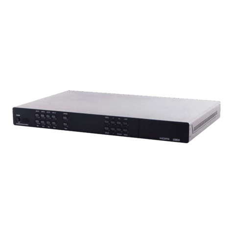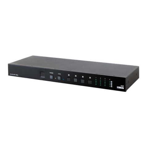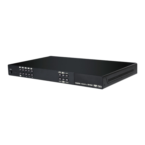
3
6. OPERATION CONTROLS AND FUNCTIONS
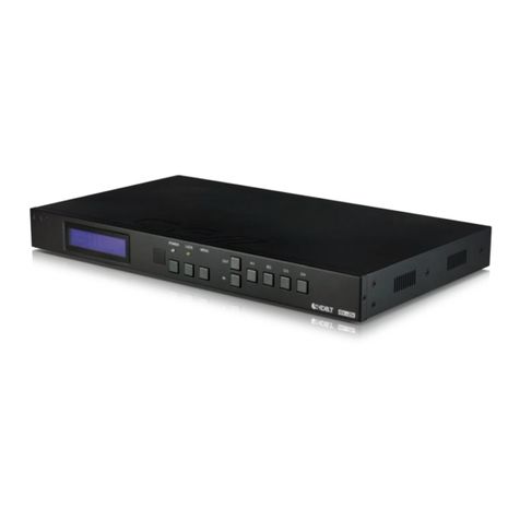
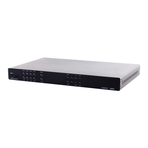
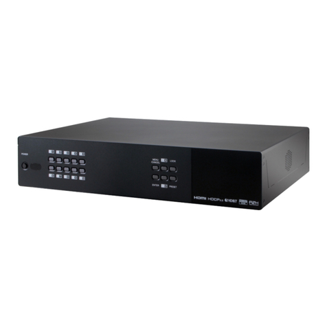
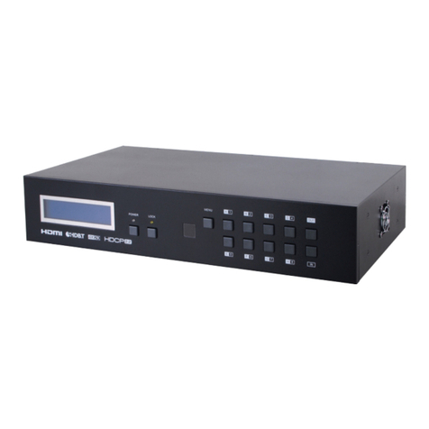
6.1 Front Panel
POWER AUTO 1 2 3 4 DISP. DISP. AUDIO EDID
SERVICE
AUDIO OUT
AOUT
B
A
B
ON
1 2 3 4
7654321 1098 11
1 IR Window: Accepts IR signals from the optional IR remote for
control of this unit only.
2 POWER LED: This LED will illuminate to indicate the unit is on and
receiving power.
3 AUTO A/B LEDs: These LEDs will illuminate to indicate if auto
switching has been enabled on the associated output.
4 INPUT 1~4 A/B LEDs: The illuminated LEDs indicate which source is
currently selected for the associated output.
5 DISP. A/B LEDs: These LEDs will illuminate to indicate when a valid
sink has been detected on the associated output port. When no
sink is detected the LED will remain off.
6 AUDIO A/B LEDs: The illuminated LED indicates which output is
selected as the source for the analog audio output. If both LEDs
are off, the analog output is muted.
Note: Only LPCM 2.0 audio sources are supported.
7 OUT A/B Buttons: Press these buttons to sequentially switch through
the available inputs for the associated output. Pressing and
holding a button for 3 seconds will enable or disable that output’s
auto switching function.
8 DISP. Button: Press this button to turn the connected displays on or
o ffusing CEC or RS-232 commands.
Note: CEC functionality must be enabled on the connected
displays. Not all displays support all CEC commands.
9 AUDIO Button: Press this button to sequentially switch the analog
audio output source between Output A, Output B, and mute.

