CYP CH-521RXHS User manual

CH-521RXHS
HDMI video scaler over CAT5e/6/7 with LAN/IR/RS-
232/Bidirectional PoE Receiver
Operation Manual
Operation Manual


DISCLAIMERS
The information in this manual has been carefully checked and
is believed to be accurate. Cypress Technology assumes no
responsibility for any infringements of patents or other rights of third
parties which may result from its use.
Cypress Technology assumes no responsibility for any inaccuracies
that may be contained in this document. Cypress also makes no
commitment to update or to keep current the information contained
in this document.
Cypress Technology reserves the right to make improvements to this
document and/or product at any time and without notice.
COPYRIGHT NOTICE
No part of this document may be reproduced, transmitted,
transcribed, stored in a retrieval system, or any of its part translated
into any language or computer le, in any form or by any means—
electronic, mechanical, magnetic, optical, chemical, manual, or
otherwise—without express written permission and consent from
Cypress Technology.
© Copyright 2014 by Cypress Technology. All Rights Reserved.
Version 1.0 January 2014
TRADEMARK ACKNOWLEDGMENTS
All products or service names mentioned in this document may be
trademarks of the companies with which they are associated.

SAFETY PRECAUTIONS
Please read all instructions before attempting to unpack, install or
operate this equipment and before connecting the power supply.
Please keep the following in mind as you unpack and install this
equipment:
• Always follow basic safety precautions to reduce the risk of re,
electrical shock and injury to persons.
• To prevent re or shock hazard, do not expose the unit to rain,
moisture or install this product near water.
• Never spill liquid of any kind on or into this product.
• Never push an object of any kind into this product through any
openings or empty slots in the unit, as you may damage parts
inside the unit.
• Do not attach the power supply cabling to building surfaces.
• Use only the supplied power supply unit (PSU). Do not use the PSU
if it is damaged.
• Do not allow anything to rest on the power cabling or allow any
weight to be placed upon it or any person walk on it.
• To protect the unit from overheating, do not block any vents or
openings in the unit housing that provide ventilation and allow for
sufcient space for air to circulate around the unit.
REVISION HISTORY
VERSION NO. DATE DD/MM/YY SUMMARY OF CHANGE
RDV1 02/01/14 Preliminary release

CONTENTS
1. Introduction............................................ 1
2. Applications........................................... 1
3. Package Contents ................................ 1
4. System Requirements............................ 1
5. Features.................................................. 2
6. Operation Controls and Functions....... 3
6.1 Front Panel ........................................3
6.2 Rear Panel.........................................4
6.3 IR Cable Pin Assignment..................5
6.4 RS-232 Pin Denitions........................5
6.5 RS-232 Commands...........................6
6.6 Remote Control................................8
6.7 OSD Menu.........................................9
6.8 Output Resolution Support............11
7. Connection Diagram .......................... 12
8. Specications ...................................... 13
9. Acronyms ............................................. 14

1
1. INTRODUCTION
The HDMI video scaler with LAN/IR/RS-232/Bidirectional PoE over Single
CAT5e/6/7 Receiver can receive uncompressed audio/video over
a single run of CAT5e/6/7 cable up to 100m or over HDMI input with
Bidirectional PoE feature. The system supports various ways of control
that can be done through on-panel buttons, IR remote, RS-232 and
OSD. The device provides full range of output resolutions up to 1080p
for HDTV timing and WUXGA(RB) for PC timing.
2. APPLICATIONS
• Extending incoming signal from CAT5e/6/7 to HDMI output
• Scale up HDMI input low resolution video on High-Denition display
• Lecture room/Showroom/Meeting room/Classroom display and
control
3. PACKAGE CONTENTS
• HDMI/CAT5e/6/7 to HDMI with LAN/IR/RS-232/Bidirectional PoE
Receiver
• IR Extender x 1
• IR Blaster x 1
• 24 V/2.7 A DC Power Adaptor
• Remote control (CR-128)
• Operation Manual
4. SYSTEM REQUIREMENTS
HDBaseT compatible Transmitter input or PS3/Blu-ray player and
output display with HDMI input jack.

2
5. FEATURES
• Supports full range HDTV and PC output resolutions up to 1080p and
WUXGA (RB)
• Receive HDMI signal and scale up to HD output
• Receive uncompressed data over a single 100 m/328 ft CAT5e/6/7
cable
• 5Play™ convergence: Video, Audio, LAN, Bidirectional PoE &
Control (IR & RS-232 bypass)
• Supports IR, Remote control, RS-232 (bypass) and on-panel controls
• Supports OSD (On Screen Display) selection and display system
information
• Provide with 24V DC power to or received from compatible PoE
Transmitter through CAT5e/6/7
• Supports Ethernet transmission rate up to 100Mbps
• Supports HDMI, Optical (S/PDIF) audio sampling rate up to 48kHz
• Support HDMI and Optical (S/PDIF) audio up to LPCM 2CH
Note:
1. This system was tested with CAT6/23AWG cables, results may vary
withcablesofadifferentspecication.
2. The PoE function is designed for powering compatible Transmitter
units only—non-PoE Transmitter will need their own power supply.
Transmitters of another brand may not be compatible.

3
6. OPERATION CONTROLS AND FUNCTIONS
6.1 Front Panel
XGA
SERVICE
MENU
ENTER
-
+
720P
HDMI OUTHDMI IN CAT/
HDMI INPUT
OPTICAL OUT
1 2 3 4 5 6 7 9
8
1SERVICE: This port is reserved for rmware update only.
2IR: IR Receiver window (accepts the remote control signal of this
device only).
3OPTICAL OUT: Connect to an amplier or active speaker with
optical cable for audio output.
4HDMI OUT: This slot is to connect with HDMI TV/Monitor
5HDMI IN: This slot is to connect with source equipment such as
DVD/PS3 player.
6MENU: Press this button to enter into the OSD menu.
7INPUTNT CAT/HDMI LED: Press this button to select input from CAT
or HDMI. When input CAT is selected the LED will illuminate in green
and when input HDMI is selected the LED will illuminated in red.
8-/+: Press these buttons to scrolled down and up in the OSD
selection.
9ENTER: Press this button to conrm the selection. Press this button
together with [–] key to switch output timing to 720p@60 instantly.
Press this button together with [+] key to switch output timing to
XGA (1024x768) instantly.

4
6.2 Rear Panel
IR
Blaster
IR
Extender
CAT5e/6/7 IN
MODE
LINK
LANRS-232 OUT
DC 24V
POWER
1 2 3 4 5 6 8 97
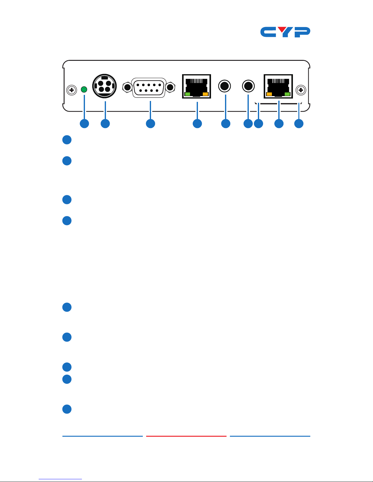
1Power LED: This LED will illuminate when the device is connected to
a power supply.
2DC 24V: Plug the 24 V DC power supply into the unit and connect
the adaptor to an AC outlet. Only one side of power is needed to
activate both Transmitter and Receiver when both obtain the PoE
function.
3RS-232 OUT: This slot is to connect with D-Sub 9-pin cable from
device equipment for receiving RS-232 commands.
4LAN: Connect to an active network for LAN sharing of a total
transmission rate up to 100Mbps. Or when a compatible LAN
equipped Transmitter is connected to an active network, this
allows the network access (including internet access if available)
to be shared between the Transmitter and Receiver. Connect any
Ethernet equipped device e.g. a Smart TV or games console to
the LAN port for that device to share the network internet access.
Note: DO NOT connect this slot with any of the CAT5e/6/7 port.
Doing so may trigger power shoot down and ruin the device.
5IR Blaster: Connect to the supplied IR Blaster cable for IR signal
transmission. Place the IR Blaster in direct line-of-sight of the
equipment to be controlled.
6IR Extender: Connect to the supplied IR Receiver cables for IR
signal reception. Ensure that remote being used is within the direct
line-of-sight of the IR Extender.
7MODE LED: This LED will illuminated when the power is connected.
8Link LED: This LED will illuminate when the slot has been connected
to the Transmitter and the Transmitter has connected with sources
that shows image on screen.
9CAT5e/6 IN: Connect to the Transmitter unit with a Single
CAT5e/6/7 cable for receiving all data signals.

5
6.3 IR Cable Pin Assignment
3
1
3
1
2
2
Power
IR Blaster Signal
NC
IR Signal
Power
Grounding
IR Extender
IR Blaster
6.4 RS-232 Pin Denitions
Pin Dene TX / RX
1 N/C
2TxD/RxD
3RxD/TxD
4 NC
5 GND
6 NC
7 NC
8 NC
9 NC
Baud Rate: 9600bps
Data bit: 8 bits
Parity: None
Flow Control: None
Stop Bit: 1

6
6.5 RS-232 Commands
COMMAND DESCRIPTION
S SOURCE 1~2 1=HDMI
2=CAT IN
R SOURCE Reports the numerical equivalent for SOURCE setting
(as above)
S OUTPUT 0~25 0=Native 12=1600×1200
1=640×480 13=1920×1080
2=800×600 16=1920×1200
3=1024×768 17=480p
5=1360×768 18=720p@60
6=1280×720 19=1080p@60
7=1280×800 20=1080i@60
8=1280×1024 22=576p
9=1440×900 23=720p@50
10=1400×1050 24=1080p@50
11=1680×1050 25=1080i@50
R OUTPUT Reports the numerical equivalent for OUTPUT
setting (as above)
S SIZE 0~6 0=OVERSCAN 4=LETTER BOX
1=FULL 5=UNDER 2
2=BEST FIT 6=UNDER 1
3=PAN SCAN
R SIZE Reports the numerical equivalent for SIZE
setting (as above)
S CONTRAST 0~60 Setups the numerical equivalent for
CONTRAST setting (as left)
R CONTRAST Reports the numerical equivalent for
CONTRAST setting
S BRIGHTNESS 0~60 Setups the numerical equivalent for
BRIGHTNESS setting (as left)
R BRIGHTNESS Reports the numerical equivalent for
BRIGHTNESS setting
S HUE 0~60 Setups the numerical equivalent for HUE
setting (as left)

7
R HUE Reports the numerical equivalent for HUE
setting
S SATURATION 0~60 Setups the numerical equivalent for
SATURATION setting (as left)
R SATURATION Reports the numerical equivalent for
SATURATION setting
S SHARPNESS 0~30 Setups the numerical equivalent for
SHARPNESS setting (as left)
R SHARPNESS Reports the numerical equivalent for
SHARPNESS setting
S NR 0~3 0=OFF 2=MIDDLE
1=LOW 3=HIGH
R NR Reports the numerical equivalent for the
NOISE REDUCTION setting (as above)
S AUDIO DELAY 0~3 0=OFF 2=110ms
1=40ms 3=150ms
R AUDIO DELAY Reports the numeric equivalent for AUDIO
DELAY setting (as above)
S AUDIO MUTE 0/1 0=ON 1=MUTE
R AUDIO MUTE Reports the numeric equivalent for AUDIO
MUTE setting (as above)
S KEY LOCK 0/1 0=ENABLE 1=DISABLE
R KEY LOCK Reports the numeric equivalent for KEY
LOCK setting (as above)
FW Checks the FIRMWARE version
S RESET 1 Setups the numerical equivalent for RESET
setting (as left)
Note:
1.All the RS-232 command will be not executed unless followed with
carriage return and LF (Line Feed).
2.Commands are case-insensitive.
3.Resolution 1~16 are RGB encoded and 17~25 are YUV encoded.
4.Digital audio supports LPCM 2CH only, please ensure source
input audio is sending LPCM 2CH's audio signal in order to avoid
unnecessarily audio noise.

8
6.6 Remote Control
1INPUT: Select input source from
CAT or HDMI.
2 EXIT: Press this button to exit the
menu or escape the current
selection under OSD.
3MENU: Press this button to enter
into the OSD menu.
4RESET: device back into the factory
default setting.
5AUTO ADJUST: This button will not
function under this model.
6 ENTER & ▲▼◄►: Press Enter to
conrm the selection or press the
arrow buttons to scrolled in the
OSD selections.
CR-128
OK
INPUT
EXIT MENU
RESET AUTO
ADJUST
1
2
4
6
3
5

9
6.7 OSD Menu
1st Layer 2nd layer 3rd Layer
DISPLAY OUTPUT Native
640X480 60
800x600 60
1024x768 60
1360x768 60
1280x720 60
1280x800 60
1280x1024 60
1440x900 60
1400x1050 60
1680x1050 60
1600x1200 60
1920x1080 60
1920x1200 60
720X480P 60
1280X720P 60
1920X1080I 60
1920X1080P 60
720X576P 50
1280X720P 50
1920X1080I 50
1920X1080P 50

10
COLOR SIZE OVER SCAN
FULL
ASPECT RATIO
PAN SCAN
LETTER BOX
UNDER 2
UNDER 1
MODE INFO INFO
ON
OFF
COLOR R
G
B
R OFFSET
G OFFSET
B OFFSET
CONTRAST 0~60
BRIGHTNESS 0~60
HUE 0~60
SATURATION 0~60
SHARPNESS 0~60
NR. OFF
LOW
MIDDLE
HIGH
AUDIO DELAY OFF
40mS
110mS
150mS
SOUND ON
MUTE

11
SETUP FACTORY RESET NO
YES
KEY LOCK OFF
ON
INFORMATION INPUT
OUTPUT
REVISION
Note: Bold Italian fonts are the Factory default setting.
6.8 Output Resolution Support
INPUT RESOLUTION HDMI
480i/576i
480p/576p
720p@50/60 Hz
1080i@50/60 Hz
1080p@50/60 Hz
VGA@60/72/75 Hz
SVGA@56/60/72/75 Hz
XGA@60/70/75 Hz
SXGA@60/75 Hz
UXGA@60 Hz
1280×800@60 Hz
1680×1050RB@60 Hz
1920×1080@60 Hz

12
7. CONNECTION DIAGRAM
XGA
SERVICE
MENU
ENTER
-
+
720P
HDMI OUTHDMI IN CAT/
HDMI INPUT
OPTICAL OUT
IR
Blaster
IR
Extender
CAT5e/6/7 IN
MODE
LINK
LANRS-232 OUT
DC 24V
POWER
CAT5e/6 In
Link
IR1 Extender
IR2 Blaster
Power
Digital Audio
Output (Optical)
DVD or Blu-ray Player
Smart TV
or
Game
Console
RS-232 Equipped
device
Compatible
Transmitter
unit with PoE
function
Display

13
8. SPECIFICATIONS
Ethernet Speed 100 Mbps
Input Video Bandwidth 300MHz / 10.2Gbps
Output Video bandwidth 165MHz / 1.65Gbps
Input Ports 1x CAT5e/6/7,
1 x IR Extender,
1 x HDMI
Output Ports 1 x HDMI,
1×IR Blaster,
1 x Optical ,
1 x RS-232,
1×LAN
CAT5e/6/7 Output Cable
Distance
Up to 100 Meters
HDMI output Resolution HD: Up to 1080p@60Hz
PC: Up to WUXGA(RB)
Audio Sampling Rate Up to 48kHz / LCPM 2CH
CAT5e/6/7 Output
Resolution
HD: Up to 1080p@60Hz
PC: Up to WUXGA(RB)
IR Frequency 30~50kHz
ESD Protection Human body model:
±8kV (air-gap discharge)
±4kV (contact discharge)
Dimensions (mm) 145 (W) x 192 (D) x 30(H)/Jacks Excluded
145 (W) x 202.75 (D) x 30(H)/Jacks Included
Weight (g) 608
Chassis Material Aluminum
Silkscreen Color Black
Operating Temperature 0˚C~40˚C / 32˚F~104˚F
Storage Temperature -20˚C ~ 60˚C / -4 ˚F ~ 140 ˚F
Relative Humidity 20 ~ 90% RH (non-condensing)
Power Consumption 17W

14
9. ACRONYMS
ACRONYM COMPLETE TERM
CAT5e Category 5 Cable
CAT6 Category 6 Cable
CAT7 Category 7 Cable
HDMI High-Denition Multimedia Interface
IR Infrared
WUXGA (RB) Widescreen Ultra Extended Graphics Array (Reduce
blanking)

Home page: http://www.cypress.com.tw
CYPRESS TECHNOLOGY CO., LTD
MPM-CH521RXHS
This manual suits for next models
1
Table of contents
Other CYP Media Converter manuals