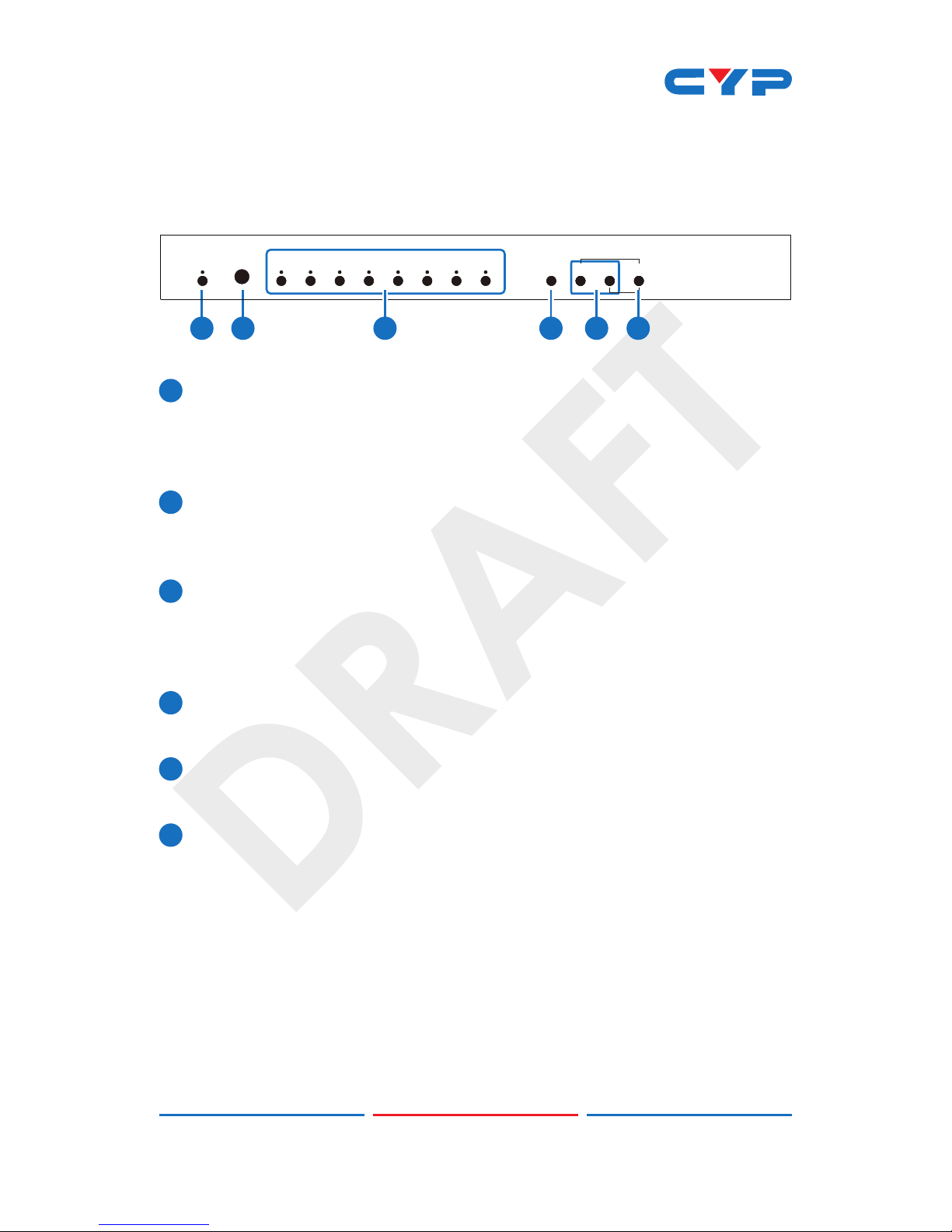
CYP CSC-5500 User manual

DRAFT
CSC-5500
Multi Input Scaler
Operation Manual
Operation Manual

DRAFT

DRAFT
DISCLAIMERS
The information in this manual has been carefully checked and
is believed to be accurate. Cypress Technology assumes no
responsibility for any infringements of patents or other rights of third
parties which may result from its use.
Cypress Technology assumes no responsibility for any inaccuracies
that may be contained in this document. Cypress also makes no
commitment to update or to keep current the information contained
in this document.
Cypress Technology reserves the right to make improvements to this
document and/or product at any time and without notice.
COPYRIGHT NOTICE
No part of this document may be reproduced, transmitted,
transcribed, stored in a retrieval system, or any of its part translated
into any language or computer le, in any form or by any means—
electronic, mechanical, magnetic, optical, chemical, manual, or
otherwise—without express written permission and consent from
Cypress Technology.
© Copyright 2011 by Cypress Technology.
All Rights Reserved.
Version VR1.0 November 2011
TRADEMARK ACKNOWLEDGMENTS
All products or service names mentioned in this document may be
trademarks of the companies with which they are associated.

DRAFT
SAFETY PRECAUTIONS
Please read all instructions before attempting to unpack, install or
operate this equipment and before connecting the power supply.
Please keep the following in mind as you unpack and install this
equipment:
• Always follow basic safety precautions to reduce the risk of re,
electrical shock and injury to persons.
• To prevent re or shock hazard, do not expose the unit to rain,
moisture or install this product near water.
• Never spill liquid of any kind on or into this product.
• Never push an object of any kind into this product through any
openings or empty slots in the unit, as you may damage parts
inside the unit.
• Do not attach the power supply cabling to building surfaces.
• Use only the supplied power supply unit (PSU). Do not use the PSU
if it is damaged.
• Do not allow anything to rest on the power cabling or allow any
weight to be placed upon it or any person walk on it.
• To protect the unit from overheating, do not block any vents or
openings in the unit housing that provide ventilation and allow for
sufcient space for air to circulate around the unit.
REVISION HISTORY
VERSION NO. DATE DD/MM/YY SUMMARY OF CHANGE
RDV1 03/12/12 Preliminary Release
RDV2 08/04/13 RS-232 Command

DRAFT
CONTENTS
1. Introduction............................................ 1
2. Applications........................................... 1
3. Package Contents ................................ 1
4. System Requirements............................ 1
5. Features.................................................. 1
6. Operation Controls and Functions....... 2
6.1 Front Panel ........................................2
6.2 Rear Panel.........................................3
6.3 Remote Control................................4
6.4 RS-232 Protocols ...............................5
6.5 RS-232 Commands...........................6
6.6 OSD MENU.........................................8
7. Connection and Installation............... 11
8. Specications ...................................... 12
8.1 Support I/O Resolution...................13

DRAFT
1
1. INTRODUCTION
The Multi Input Scaler has CV, Component, PC, and HDMI inputs and
can scale the signal into HDMI, VGA with audio output ports. This high
performance multi input scaler supports HDMI output resolution up to
1080p /WUXGA and Analog Digital Conversion (ADC) & Digital Analog
Conversion (DAC) allowing a wide range of AV signal to be insert to a
high-Denition signal and displaying. Further, with OSD, remote, RS-232,
Telnet and on-panel controls that makes whole for this Digital Video
Scaler a friendly using device.
2. APPLICATIONS
• Lecture hall
• Meeting room
• Conference hall
3. PACKAGE CONTENTS
• Multi Input Scaler
• Remote Control (CR-122)
• D-Sub to RCA adaptor cable
• Power Adaptor
• Operation Manual
4. SYSTEM REQUIREMENTS
Input source equipments such as Blu-ray/DVD players or PC/NB,
output display and amplier or speakers.
5. FEATURES
• Supports multi AV inputs to HDMI or PC/HD outputs
• Supports EDID and HDCP
• Supports 3D de-interlace, noise reduction and 3D Comb lter
• Supports frame rate conversion
• Supports RS-232, Telnet & Controls
• Support output timing hot keys switching
• HDMI compatible with DVI

DRAFT
2
6. OPERATION CONTROLS AND FUNCTIONS
6.1 Front Panel
1 2
POWER CV COMP PC 1 PC 2 PC 3 HDMI 1 HDMI 2 HDMI 3MENU
XGA
ENTER
-
+
720P
3 4 5 6
1POWER & LED:
Press this button to switch ON or set the device to standby mode.
Once the device is connected with power supply the LED will
illuminate and the device will switch to ON automatically.
2IR:
This IR window receives only the IR signal from the remote control
included in the package.
3INPUT button and LEDs:
Press this button sequentially to switch in between the input sources
rotationally. LED will illuminate accordingly to the selected input
source.
4MENU:
Press this button to enter into the OSD menu.
5-/+:
Press these buttons to scrolled down and up in the OSD selection.
6ENTER:
Press this button to conrm the selection. Press this button together
with + button to switch output to XGA instantly or with - button to
switch output to 720p instantly.

DRAFT
3
6.2 Rear Panel
POWER
DC 5V
CONTROL
HDMI 2HDMI 1 PC/HD
RS232 COAX AUDIO
SERVICE
OUTPUT
HDMI 1 HDMI 2 HDMI 3 PC 1 PC 2 PC 3 Cr/Pr Cb/Pb
RL
YRLCV
AUDIO
INPUT
4 5 8
1 2 3 6 7
IR IN
1IR IN:
Plug in the IR extender cable for IR signal receiving from the
included remote control.
2SERVICE:
Reserved for factory use only.
3RS-232:
Connect with PC/NB and use RS-232 command to control the
device.
4OUTPUT:
HDMI 1 & 2: Connect to HDMI display or amplier for video or video
and audio display.
COAX: Connect to active speaker or amplier for audio output in
digital format.
When the input audio source signal is with bitstream format and
the audio source setting is at Auto, coaxial output will bypass the
input audio signal which may be 5.1CH or 7.1CH according to
audio input format.
AUDIO: Connect to active speaker or amplier for audio output in
stereo format.
PC/HD: Connect to monitor/display for video output display. For
HD output,use D-Sub 9pin to 3 RCA adaptor cable for output HD
timing from 480p~1080p.
5INPUT:
HDMI 1~3: Connect to HDMI source equipment such as Blu-ray/
DVD player for both video and audio signal sending.
PC 1~3: Connect with PC/NB source equipment for video signal
input with D-Sub 15pin cable.
L/R: Connect to source equipment’s L/R output corresponding
tothe input jack below with 3.5Ø phone jack for audio signal

DRAFT
4
sending.The priority audio input of HDMI is from HDMI, only when
HDMI input has no audio signal the L/R audio will be inserted
into.
YCbCr/HDPbPr + L/R: Connect to source equipment such as video/
DVD player for both video and audio signal sending.
CV + L/R: Connect to source equipment such as video/DVD player
for both video and audio signal sending.
5CONTROL:
This port is the link for Telnet or Web GUI controls, connect to an
active Ethernet link with an RJ45 terminated cable (for further
details, please refer to section.
6POWER:
Switch this power toggle to turn on and activate the device or to
turn off to shut it down.
7DC 5V:
Plug the power adaptor included in the package and connect it
to the AC wall outlet for power supply.
6.3 Remote Control
1POWER: Press this button to switch
ON or set the device to standby
mode. Once the device is
connected with power supply.
2HDMI1~3/PC1~3/CV/COMP: Press
these hot keys to switch input
source instantly.
3EXIT: Press this button to exit the
menu or the current selection under
OSD.
4MENU: Press this button to enter into
the OSD menu.
5 OK & ▲▼◄►: Press OK to conrm
the selection or press the arrow
buttons to scrolled in the OSD
selections.
6RESET: Press this button to set the
device back into the factory default
setting.
CR-122
POWER
PC1PC2 PC3
CV COMP
EXIT MENU
OK
RESET AUTO
ADJUST
3
6
1
4
7
5
8
2
HDMI2HDMI1 HDMI3

DRAFT
5
7AUTO ADJUST: Press this button when output image is not tting the
display's screen perfectly. The device will auto adjust the image to
full screen.
8 ◄►: Press right and left buttons to increase and decrese the
volume.
6.4 RS-232 Protocols
CSC-5500
►
◄
Remote Control
PIN Assignment PIN Assignment
1 NC 1 NC
2Tx 2Rx
3Rx 3Tx
4 NC 4 NC
5 GND 5 GND
6 NC 6 NC
7 NC 7 NC
8 NC 8 NC
9 NC 9 NC
Baud Rate: 19200bps
Data bit: 8 bits
Parity: None
Flow Control: None
Stop Bit: 1

DRAFT
6
6.5 RS-232 Commands
Command Description Contents
S SOURCE 1~8 Select input source HDMI1(1) / HDMI2(2) /
HDMI3 (3) / YPBPR(4) /
VIDEO(5) / PC(6) / PC2(7)
/ PC3(8)
R SOURCE Inquire input source
S OUTPUT 0~21 Select output timing 640*480(0)/800*600(1)/
1024*768(2)/1280*768(3)/
1360*768(4)/1280*720(5)/
1280*800(6)/1280*1024(7)/
1440*900(8)/1400*1050(9)/1
680*1050(10)/
1600*1200(11)1920*1080(12)/
1920*1200(13)/
480p(14)/720p 60(15)/
1080i 60(16)/ 1080p 60(17)/
576p(18)/720p 50(19)/
1080i 50(20)/ 1080p 50(21)
R OUTPUT Inquire output timing
S SIZE 0~6 Select output size OVERSCAN(0) / FULL(1) /
FOLLOW INPUT(2) / PAN
SCAN(3)/LETTER BOX(4) /
UNDER 2(5) / UNDER 1(6)
R SIZE Inquire output size
S INPUTHDCP 0/1 Select HDCP setting ON(0) / OFF(1)
R INPUTHDCP Inquire HDCP setting ON(0) / OFF(1)
S CONTRAST 0~60 Contrast Setting
R CONTRAST Inquire contrast setting
S BRIGHTNESS 0~60 Brightness setting
R BRIGHTNESS Inquire brightness setting
S HUE 0~60 Hue setting
R HUE Inquire hue setting
S SATURATION 0~60 Saturation setting
R SATURATION Inquire saturation setting
S SHARPNESS 0~30 Sharpness setting
R SHARPNESS Inquire sharpness setting

DRAFT
7
S NR 0~3 Noise reduction setting OFF(0) / LOW (1) /
MIDDLE(2) / HIGH(3)
R NR Inquire noise reduction
setting
S VOLUME 0~100 Volume Setting
R VOLUME Inquire Volume setting
S AUDIODELAY 0~3 Audio delay setting OFF(0) / 40ms (1) /
110ms(2) / 150ms(3)
R AUDIODELAY Inquire audio delay
setting
S AUDIOMUTE 0/1 Audio mute setting ON(0) / MUTE(1)
R AUDIOMUTE Inquire audio mute
setting
S HDMIAUDIO 0/1 HDMI Audio Setting AUTO(0) / EXT.(1)
R HDMIAUDIO Inquire Audio setting
S KEY LOCK 0/1 Key lock setting ENABLE(0) / DISABLE(1)
R KEY LOCK Inquire key lock setting
S RESET 1 Pre-reset
S POWER 0/1 Firmware checking OFF(0) / ON(1)
R POWER Request power status
PORT (0~8) Set active port
when repower on
LAST MEMORY(0) /
HDMI(1) / HDMI2(2) /
HDMI3(3) / YPBPR(4) /
VIDEO (5) / PC(6) /
PC2(7) / PC3(8)
ST FW vers. & source info. 0.00~x.xx
SOURCE: HDMI ~ PC3
PORT ON:LAST ~ PC3
Other RS-232 command will be not executed unless followed with a
carriage return + LF and commands are case-insensitive.

DRAFT
8
6.6 OSD MENU
1st Layer 2nd Layer 3rd Layer 4th Layer
DISPLAY
OUTPUT
640x480 60
800x600 60
1024x768 60
1280x768 60
1360x768 60
1280x720 60
1280x800 60
1280x1024 60
1440x900 60
1400x1050 60
1680x1050 60
1600x1200 60
1920x1080 60
1920x1200 60
1280X720P 60
1920X1080I 60
1920X1080P 60
720X576P 50
1280X720P 50
1920X1080I 50
1920X1080P 50
SIZE (VIDEO
mode only)
OVER SCAN
FULL
FOLLOW INPUT
PAN SCAN
LETTER BOX
UNDER 2
UNDER 1
MODE INFO
OFF
INFO
ON
INPUT HDCP
(HDMI mode
only)
OFF
ON
PC (PC mode
only)
AUTO SETUP
H_POSITION
V_POSITION
PHASE
CLOCK
WXGA/XGA XGA
WXGA
RESET

DRAFT
9
COLOR
CONTRAST 0~60 (30)
BRIGHTNESS 0~60 (30)
COLOR
R 0~1023 (512)
G 0~1023 (512)
B 0~1023 (512)
R OFFSET
0~1023 (512)
G OFFSET
0~1023 (512)
B OFFSET
0~1023 (512)
HUE 0~60 (30)
SATURATION 0~60 (30)
SHARPNESS 0~30 (0)
NR.
OFF
LOW
MIDDLE
HIGH
AUDIO
VOLUME 0~100 (100)
DELAY
OFF
40mS
110mS
150mS
SOUND ON
MUTE
SOURCE(HDMI
mode only)*1
AUTO
EXT.
FACTORY
RESET
KEY LOCK OFF
ON
POWER SAVE OFF
ON
IP MODE DHCP
STATIC
SET STATIC IP
IP ADDRESS 0.0.0.0.~255.255.
255.255*2
SUBNET MASK 0.0.0.0.~255.255.
255.255*3
Def. Getway 0.0.0.0.~255.255.
255.255*4
INFORMATION INPUT
OUTPUT
REVISION
IP ADDRESS

DRAFT
10
Factory default setting.
*1 When Audio Source is set on Auto, the device will send audio signal
according to input source. If input signal is with HDMI, the device
will use internal signal and if input signal is with DVI, the device will
use external L/R audio. When Audio Source is set on EXT, the device
will use external L/R audio.
*2 192.168.0.1 (Default Setting)
*3 255.255.255.0 (Default Setting)
*4 192.168.0.254 (Default Setting)

DRAFT
11
7. CONNECTION AND INSTALLATION
POWER
DC 5V
CONTROL
HDMI 2HDMI 1 PC/HD
RS232 COAX AUDIO
SERVICE
IR IN
OUTPUT
HDMI 1 HDMI 2 HDMI 3 PC 1PC 2PC 3 Cr/Pr Cb/Pb
RL
YRLCV
AUDIO
INPUT
AVR
Monitor/Display
TV or Monitor PC/ NB
AVR with Coaxial Input
DVI to HDMI sourcePC/NB
Wireless Router(with
Internet Connection)
Smartphone or Tablet
Component with Stereo
Audio from DVD Player
Composit video
with Stereo Audio
from DVD Player

DRAFT
12
8. SPECIFICATIONS
Input Port 1 x Component,
3 x VGA,
3 x HDMI,
6 x LR ,
1 x USB (service only),
1 x RS-232 (Control Only)
Output Port 2 x HDMI,
1 x PC/HD,
1 x Coaxial, 1 x L/R
Supports Input Resolution Up to UXGA & 1080p
Supports Output Resolution Up to WUXGA & 1080p
Power Supply 5V/3A DC (US/EU standards, CE/FCC/
UL certied)
Dimensions (mm) 432 mm(W) x 183 mm(D) x 47 mm(H)
Weight(g) 2140
Chassis Material Metal
Silkscreen Color Black
Operating Temperature 0˚C ~ 40˚C / 32 ˚F ~ 104 ˚F
Storage Temperature -20˚C ~ 60˚C / -4 ˚F ~ 140 ˚F
Relative Humidity 20 ~ 90% RH (non-condensing)
Power Consumption(W) 10.5

DRAFT
13
8.1 Support I/O Resolution
Input
Resolution CV Component PC HDMI
NTSC/PAL V
480i/576i V V
480p/576p V V
720p@50/60Hz V V
1080i@50/60Hz V V
1080p@50/60Hz V V
VGA@60/72/75Hz V V
SVGA@56/60/72/75Hz V V
XGA@60/70/75Hz V V
SXGA@60/75Hz V V
UXGA@60Hz V V
1280x800@60Hz V V
1680x1050RB@60Hz V V
1920x1080@60Hz V V
Output
Resolution PC/HD HDMI
480p/576p V (HD) V
720p@50/60Hz V (HD) V
1080i@50/60Hz V (HD) V
1080p@50/60Hz V (HD) V
VGA@60Hz V V
SVGA@60Hz V V
XGA@60Hz V V
SXGA@60Hz V V

DRAFT
14
UXGA@60Hz V V
1280x768@60Hz V V
1280x800@60Hz V V
1360x768@60Hz V V
1400x1050@60Hz V V
1440x900@60Hz V V
1680x1050@60Hz V V
1920x1200@60Hz V V

DRAFT
Home page: http://www.cypress.com.tw
CYPRESS TECHNOLOGY CO., LTD
20121224 MPM-CSC5500
Other manuals for CSC-5500
2
Table of contents
Other CYP Media Converter manuals