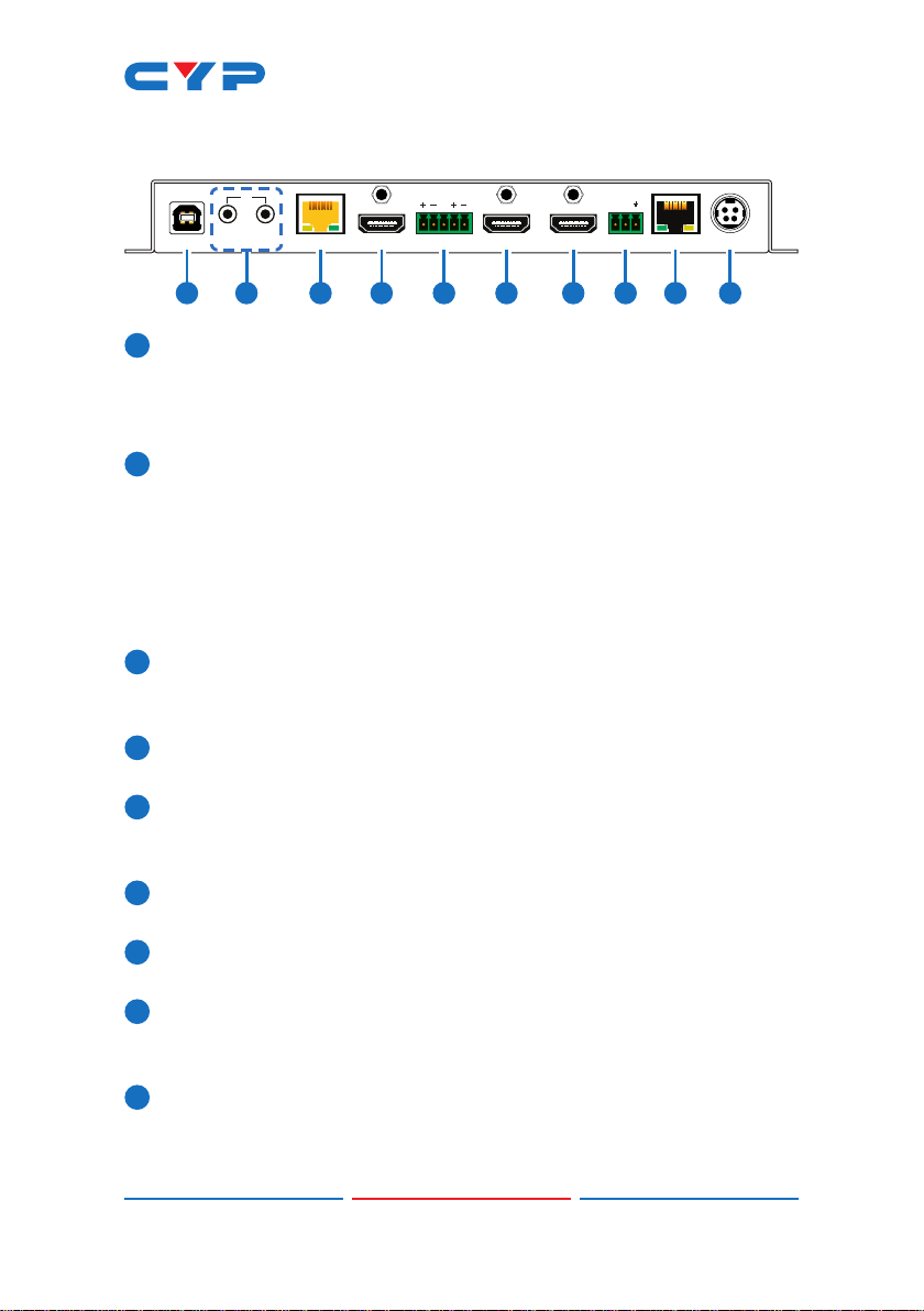
CYP CH-2603RX User manual

CH-2603RX
HDMI/HDBaseT/USB to HDMI Receiver
Operation Manual
Operation Manual


DISCLAIMERS
The information in this manual has been carefully checked and
is believed to be accurate. Cypress Technology assumes no
responsibility for any infringements of patents or other rights of third
parties which may result from its use.
Cypress Technology assumes no responsibility for any inaccuracies
that may be contained in this document. Cypress also makes no
commitment to update or to keep current the information contained
in this document.
Cypress Technology reserves the right to make improvements to this
document and/or product at any time and without notice.
COPYRIGHT NOTICE
No part of this document may be reproduced, transmitted,
transcribed, stored in a retrieval system, or any of its part translated
into any language or computer le, in any form or by any means—
electronic, mechanical, magnetic, optical, chemical, manual, or
otherwise—without express written permission and consent from
Cypress Technology.
© Copyright 2018 by Cypress Technology.
All Rights Reserved.
TRADEMARK ACKNOWLEDGMENTS
All products or service names mentioned in this document are
trademarks of the companies with which they are associated.

SAFETY PRECAUTIONS
Please read all instructions before attempting to unpack, install or
operate this equipment and before connecting the power supply.
Please keep the following in mind as you unpack and install this
equipment:
• Always follow basic safety precautions to reduce the risk of re,
electrical shock and injury to persons.
• To prevent re or shock hazard, do not expose the unit to rain,
moisture or install this product near water.
• Never spill liquid of any kind on or into this product.
• Never push an object of any kind into this product through any
openings or empty slots in the unit, as you may damage parts
inside the unit.
• Do not attach the power supply cabling to building surfaces.
• Use only the supplied power supply unit (PSU). Do not use the PSU
if it is damaged.
• Do not allow anything to rest on the power cabling or allow any
weight to be placed upon it or any person walk on it.
• To protect the unit from overheating, do not block any vents or
openings in the unit housing that provide ventilation and allow for
sufcient space for air to circulate around the unit.
• Please completely disconnect the power when the unit is not in
use to avoid wasting electricity.
VERSION HISTORY
REV. DATE SUMMARY OF CHANGE
RDV1 2019/04/29 Preliminary release

CONTENTS
1. Introduction......................................................1
2. Applications.....................................................1
3. Package Contents ..........................................2
4. System Requirements......................................2
5. Features............................................................3
6. Operation Controls and Functions.................4
6.1 Front Panel................................................. 4
6.2 Rear Panel.................................................. 5
6.3 IR Cable Pinouts ........................................ 6
6.4 RS-232 Pinout and Defaults...................... 6
6.5 WebGUI Control........................................ 7
6.5.1 Video Select Tab.............................. 9
6.5.2 EDID Tab.......................................... 11
6.5.3 HDCP Tab........................................ 13
6.5.4 USB Tab............................................ 14
6.5.5 Audio Tab ....................................... 15
6.5.6 System Tab...................................... 16
6.6 Telnet Control.......................................... 17
6.7 RS-232 and Telnet Commands.............. 18
7. Connection Diagram ....................................29
8. Specications ................................................30
8.1 Technical Specications ........................ 30
8.2 Video Specications............................... 32
8.3 Audio Specications............................... 34
8.3.1 Digital Audio................................... 34
8.3.2 Analog Audio................................. 34
8.4 Cable Specications .............................. 35
8.5 HDBaseT Features.................................... 36
9. Acronyms.......................................................37

1
1. INTRODUCTION
This HDBaseT 2.0 Receiver is designed for use in environments needing
a wide range of exibility when it comes to inputs, outputs, and
control. With a 2 by 2 matrix arrangement of HDBaseT & HDMI inputs
and dual HDMI outputs this Receiver can handle a variety of source
routing scenarios. The HDMI input and outputs support resolutions
up to a maximum of 4K@60Hz (4:4:4, 8-bit) while the HDBaseT input
supports resolutions up to a maximum of 4K@60Hz (YUV 4:2:0, 8-bit). A
balanced analog stereo audio breakout is also provided (LPCM 2.0
sources only) allowing for professional local powered speakers to be
easily added to the system. The HDBaseT input not only supports video
and audio but also bi-directional Ethernet, RS-232, USB, and IR.
When paired with this unit’s standard Transmitter, up to 3 switchable
USB 2.0 host (Type B) connections are available (2 on the Transmitter, 1
on the Receiver) which connect to 6 USB 2.0 (Type A) device ports (3
on the Transmitter, 3 on the Receiver) for a multi-source, bi-directional,
and highly exible KVM conguration (Note: Only 1 USB host may be
active at a time).
This Receiver (PSE) can provide PoH (Power over HDBaseT) power to
the connected HDBaseT Transmitter (PD) (compatible Transmitters
only), allowing for greater exibility within different installation
scenarios. This unit is controllable via front-panel controls, WebGUI,
Telnet, and RS-232.
2. APPLICATIONS
• Lecture room display and control
• Showroom display and control
• Meeting room presentation and control
• Classroom display and control

2
3. PACKAGE CONTENTS
• 1×HDMI/HDBaseT/USB to HDMI Receiver
• 1×24V/3.75A DC Power Adapter
• 1×3.5mm to IR Blaster Cable
• 1×3.5mm to IR Extender Cable
• 1×Shockproof Feet (Set of 4)
• 1×Operation Manual
• 1x power cord
• 1x3-pin terminal block
• 1x5-pin terminal block
4. SYSTEM REQUIREMENTS
• HDMI source equipment such as a media player, video game
console, or set-top box.
• A compatible HDBaseT transmitter with PoH (PD) support is
recommended.
• HDMI receiving equipment such as HDTVs, monitors or audio
ampliers.
• The use of Premium High Speed HDMI cables, and industry standard
Cat.6, Cat.6a or Cat.7, is highly recommended.

3
5. FEATURES
• HDMI input and output with 3D & 4K video support (18Gbps)
• HDCP 1.x & 2.2 compliant
• HDBaseT 2.0 compatible
• Selectable HDMI and HDBaseT inputs
• HDMI input supports resolutions up to 4K@60Hz (4:4:4, 8-bit)
• HDBaseT input supports resolutions up to 4K@60Hz (YUV 4:2:0, 8-bit)
• HDMI outputs support resolutions up to 4K@60Hz (4:4:4, 8-bit)
• 2×2 matrix switching (both HDMI outputs are independent)
• Supported HDBaseT features: HD video and audio, 100BaseT
Ethernet, PoH, and control (bi-directional IR/RS-232/USB pass-
through)
• Supports pass-through of 8 channel LPCM, Bitstream & HD Bitstream
audio formats
• Balanced analog stereo audio breakout
• Flexible USB host selection using front panel buttons
• Multiple USB hosts may be connected at once (up to 3 total,
between the Tx and a compatible Rx unit) with a single selected
host active at a time
• Supports providing PoH power from Receiver (PSE) to Transmitter (PD)
(compatible Transmitters only)
• Controllable via front panel buttons, WebGUI, Telnet, and RS-232

4
6. OPERATION CONTROLS AND FUNCTIONS
6.1 Front Panel
POWER
LINK
1OUT1
2OUT2
LOCAL
RS-232
HDMI OUT 1OUT 2CAT5e/6/7 USB
SELECT
VIDEO SELECT SERVICE
1 2 3 4 5 6
1POWER LED: This LED will illuminate to indicate the unit is on and
receiving power.
2LINK LED: This LED will illuminate solidly when a live connection with
a compatible Transmitter is active.
3LOCAL RS-232 Port: Connect directly to a PC, laptop, or other
serial control device with a 3.5mm adapter cable to send RS-232
commands to control the unit.
4OUT 1 Button & LEDs: Press this button to toggle between the
available inputs for HDMI output 1. The OUT 1 LED will illuminate to
indicate which source is currently selected.
OUT 2 Button & LEDs: Press this button to toggle between the
available inputs for HDMI output 2. The OUT 2 LED will illuminate to
indicate which source is currently selected.
5USB Device Ports (Type A): Connect directly to standard USB
devices such as a mouse, keyboard or ash drive to extend their
USB functionality to the currently active USB Host Port.
6USB SELECT Button & LED: Press this button to toggle between using
the USB Host Port on the Receiver or the USB Host Ports on the
connected Transmitter. The LED will illuminate when the USB Host
Port on the Receiver is active. If the LED is off, then one of the USB
Host Ports on the connected Transmitter is active.
Note: Changing the USB host will force the HDBaseT connection to
briey disconnect while it recongures. The connected host (PC,
Laptop, etc.) may also take a moment to detect all available
devices.

5
6.2 Rear Panel
DC 24VLAN
RS-232
BYPASS
OUT 2OUT 1HDMI INCAT5e/6/7 INUSB OUT
IR
IN
TX RX
ANALOG OUT
LR
G
10987654321
1USB Host Port (Type B): Connect directly to a standard USB host
such as a PC or laptop to extend their USB functionality to all
currently connected USB devices.
Note: Only one USB Host Port may be active at a time.
2IR IN Port: Connect to the provided IR Extender to receive IR
control signals and extend them to devices connected to the
other end of the HDBaseT connection. Ensure that the remote
being used is within direct line-of-sight of the IR Extender.
IR OUT Port: Connect to the provided IR Blaster to transmit IR signals
from the other end of the HDBaseT connection to devices within
direct line-of-sight of the IR Blaster.
3CAT5e/6/7 IN Port: Connect to a compatible HDBaseT Transmitter
with a single Cat.5e/6/7 cable for reception of all data signals. PoH
will also be supplied to a connected compatible PD Transmitter.
4HDMI IN Port: Connect to HDMI source equipment such as a media
player, game console, or set-top box.
5ANALOG OUT Terminal Block: Connect to powered speakers or an
amplier using a 5-pin terminal block for balanced stereo analog
audio output.
6HDMI OUT 1 Port: Connect to an HDMI TV, monitor, or amplier for
digital video and audio output.
7HDMI OUT 2 Port: Connect to an HDMI TV, monitor, or amplier for
digital video and audio output.
8BYPASS RS-232 Terminal Block: Connect to a PC, laptop, or other
serial control device with a 3-pin adapter cable for the extension
of RS-232 signals to the Transmitter.
9LAN Port: Connect directly, or through a network switch, to your
PC/laptop to control the unit via Telnet/WebGUI and to extend the
network across the HDBaseT connection.

6
10 DC 24V Port: Plug the 24V DC power adapter into this port and
connect it to an AC wall outlet for power.
6.3 IR Cable Pinouts
IR Blaster
Cabl
e
1
2
3
Infrared
Power
Not U
sed
IR Extender
Cabl
e
1
2
3
Infr
ared
Power
Ground
6.4 RS-232 Pinout and Defaults
Serial Port Default Settings
Baud Rate 19200
Data Bits 8
Parity Bits None
Stop Bits 1
Flow Control None
1
2
3
RxD
GND
TxD
3-pin
Terminal Block
3.5mm to DE-9
A
dapter Cable
RxD
TxD
GND
1
2
3

7
6.5 WebGUI Control
• Device Discovery
Please obtain the “Device Discovery” software from your authorized
dealer and save it in a directory where you can easily nd it.
Connect the unit and your PC/Laptop to the same active network
and execute the “Device Discovery” software. Click on “Find Devices
on Network” and a list of devices connected to the local network will
show up indicating their current IP address.
Note: The unit’s default IP address is 192.168.1.50.
By clicking on one of the listed devices you will be presented with the
network details of that particular device.
1) IP Mode: If you choose, you can alter the static IP network settings
for the device, or switch the unit into DHCP mode to automatically
obtain proper network settings from a local DHCP server. To switch
to DHCP mode, please select DHCP from the IP mode drop-down,
then click “Save” followed by “Reboot”.
2) WebGUI Hotkey: Once you are satised with the network settings,
you may use them to connect via Telnet or WebGUI. The network
information window provides a convenient link to launch the
WebGUI directly.

8
• WebGUI Overview
After connecting to the WebGUI’s address in a web browser, the
login screen will appear. Please enter the appropriate user name and
password then click “Submit” to log in.
Note: The default user name and password is “admin”.
On the left side of the browser you will see the following menu tabs
where all primary functions of the unit are controllable via the built in
WebGUI. The individual functions will be introduced in the following
sections.
Clicking the red “Logout” tab will automatically log the currently
connected user out of the WebGUI and return to login page. Clicking
on the “Transmitter Webpage” button will open a new webpage
showing the WebGUI for the connected Transmitter.

9
6.5.1 Video Select Tab
This tab provides A/V routing control, auto switch controls, and I/O
renaming options.
To assign a new A/V route, please click the button of the Output you
wish to route a source to on the left and then click on the button
of the preferred Input port on the right. Selecting both Outputs
simultaneously is possible.
As you select each button they will become yellow. The new route will
become active immediately and the routing information displayed on
the buttons will change accordingly.
1) Video Select:
■ Output: Buttons for selecting the Output (A or B) to route A/
V Inputs to. Details about the Output names and currently
selected Input are also displayed here. Clicking on the “edit”
icon ( ) opens up the Edit Output window which allows for
changing the Output’s name.
■ Input: Buttons for selecting the Input (1 through 2) to route
to the selected Output. The current Input names are also
displayed here. Clicking on the “edit” icon ( ) opens up the
Edit Input window which allows for changing the Input’s name.

10
2) Auto Switch: Auto switching may be enabled or disabled
individually for each Output. Click on the On/Off slider to toggle
the behavior of the selected Output.
This unit can store up to two routing presets. Presets can be utilized
to store multiple different routing states in advance for rapid,
hassle-free, recall.
3) Preset Set: Once you have the routing set the way you like, you
can click the “Preset Set” icon ( ) in the upper right corner of the
tab to open the Preset Set window. Click on the preferred Preset
button when you are ready to commit the preset to memory. You
may also rename the preset at this stage by selecting the “edit”
icon ( ) .
4) Preset Recall: When you wish to load a previously stored preset,
please click the “Preset Recall” icon ( ) and you will be presented
with a choice of the 2 available presets. The preset will load
immediately upon selecting the button..

11
6.5.2 EDID Tab
This tab provides the option of six standard EDIDs, two sink sourced
EDIDs and two customer uploaded User EDIDs that can be assigned to
either or both of the input ports.

12
1) Customer EDID Settings:
■ Save Name: To modify the name of a User EDID, simply type the
new name in the space provided and then click on the “Save
Name” button to conrm the change.
■ Upload: To upload a User EDID, press the “Upload” button next
to the User EDID slot you wish to upload into. An EDID Upload
window will appear, allowing you to locate and upload the
preferred EDID le (*.bin format) from a local PC. Once the
correct le has been selected, please click the “Upload”
button in the window, and the le will be transferred to the unit.
■ Download: To save an existing User EDID to your local PC, press
the “Download” button next to the User EDID slot you wish to
save. Depending on your browser settings you will either be
asked where to save the downloaded le, or the le will be
transferred to the default download location on your PC.
2) Sink EDID Download: To save the EDID from a connected display to
your local PC, select the sink from the dropdown list then press the
“Download” button. Depending on your browser settings you will
either be asked where to save the downloaded le, or the le will
be transferred to the default download location on your PC.
3) Set EDID Input Content/EDID Source: The Set EDID Input Content
section allows for the assignment of a specic EDID to either Input
port. Click on one or more input buttons on the left and then select
the new EDID source to use from the choices on the right. The
buttons will change color as you select them and the EDID change
will occur immediately across all selected Inputs.
Note: In most cases, assigning a new EDID to an input will cause
the affected input to briey blink out while the source adapts to
the new information.

13
This unit provides the following 6 default EDIDs:
Unit’s Default EDIDs
FHD/2CH 1920×1080p@60Hz (148MHz) &
8-bit color
LPCM 2.0
FHD/MCH 1920×1080p@60Hz (148MHz) &
8-bit color
LPCM 7.1 &
Bitstream
UHD/2CH 3840×2160p@30Hz (297MHz) &
Deep Color (8/10/12-bit)
LPCM 2.0
UHD/MCH 3840×2160p@30Hz (297MHz) &
Deep Color (8/10/12-bit)
LPCM 7.1 &
Bitstream
UHD+/2CH 3840×2160p@60Hz (594MHz) &
Deep Color (8/10/12-bit)
LPCM 2.0
UHD+/MCH 3840×2160p@60Hz (594MHz) &
Deep Color (8/10/12-bit)
LPCM 7.1 &
Bitstream
Note: In some rare cases it is possible for custom or external EDIDs to
cause compatibility issues with certain sources. If this happens, it is
recommended to switch to one of the 6 default EDIDs for maximum
compatibility.
6.5.3 HDCP Tab
This tab provides the option of three HDCP operational modes that
can be assigned to any of the input ports.
1) Set HDCP Input Mode/HDCP Mode: The HDCP Input Mode section
allows for the assignment of a specic HDCP behavior to any Input
port. Click on one or more input buttons on the left and then select
the new HDCP mode to use from the choices on the right. The

14
buttons will change color as you select them and the change in
HDCP behavior will occur immediately across all selected Inputs.
“Reference to Source” will make the input operate using the HDCP
version required by the connected source. “Reference to Display”
will limit the input to only accept the HDCP version supported by
the connected display. Selecting “Disable” will completely disable
HDCP support on that input.
6.5.4 USB Tab
This tab provides a way to select which USB Host Port (USB Type B) is
currently active.
Note: Changing the USB host will force the HDBaseT connection to
briey disconnect while it recongures. The connected host (PC,
Laptop, etc.) may also take a moment to detect all available devices.
1) Set USB Mode: Select the preferred USB Host Port, from the
displayed selection, to use as the currently active connection. The
change will occur immediately and all USB Device Ports (USB Type
A) on the Transmitter and Receiver will connect to the new host.
Note: When "Remote Host" is selected, Host Port 1 on the Transmitter
will become active. To select Host Port 2 on the Transmitter, please
use the Transmitter's WebGUI.

15
6.5.5 Audio Tab
This tab provides control over the volume level of the balanced
analog audio output.
Note: HDMI audio output is always a direct pass-through from the
selected source and is not affected by the controls on this tab.
1) Volume: Allows the adjustment of the balanced analog output’s
volume level. The available adjustment range is -103 to +24 dB. The
analog output may also be muted or unmuted using the toggle
switch.
Note: The analog output can only support LPCM 2.0 sources.
Bitstream sources will be automatically muted.
Table of contents
Other CYP Receiver manuals

CYP
CYP PUV-2100RX-AVLC User manual

CYP
CYP RXWPBD User manual

CYP
CYP CH-1106TX & RX User manual

CYP
CYP PU-515PL-WPRX User manual

CYP
CYP CH-107RXN User manual

CYP
CYP AVX-101F-KIT User manual

CYP
CYP CA-HDMI100R User manual

CYP
CYP CSC-6012TX User manual

CYP
CYP IP-7050RX-TG User manual

CYP
CYP CH-U331RX User manual