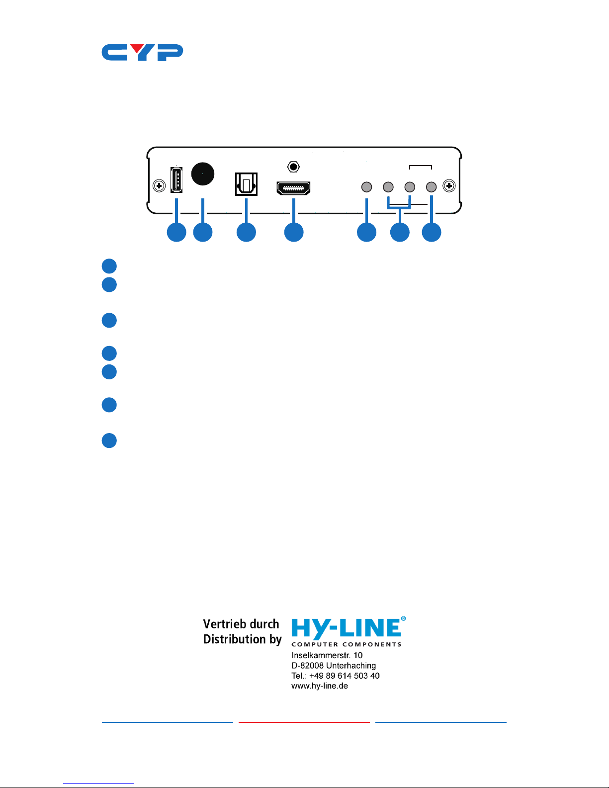
CYP CH-517RXHS User manual

CH-517RXHS
HDMI Scaler over CAT5e/6/7 Receiver with LAN/
RS-232/IR/Bidirectional PoE
Operation Manual
Operation Manual


DISCLAIMERS
The information in this manual has been carefully checked and
is believed to be accurate. Cypress Technology assumes no
responsibility for any infringements of patents or other rights of third
parties which may result from its use.
Cypress Technology assumes no responsibility for any inaccuracies
that may be contained in this document. Cypress also makes no
commitment to update or to keep current the information contained
in this document.
Cypress Technology reserves the right to make improvements to this
document and/or product at any time and without notice.
COPYRIGHT NOTICE
No part of this document may be reproduced, transmitted,
transcribed, stored in a retrieval system, or any of its part translated
into any language or computer le, in any form or by any means—
electronic, mechanical, magnetic, optical, chemical, manual, or
otherwise—without express written permission and consent from
Cypress Technology.
© Copyright 2011 by Cypress Technology. All Rights Reserved.
Version 1.0 September 2011
TRADEMARK ACKNOWLEDGMENTS
All products or service names mentioned in this document may be
trademarks of the companies with which they are associated.

SAFETY PRECAUTIONS
Please read all instructions before attempting to unpack, install or
operate this equipment and before connecting the power supply.
Please keep the following in mind as you unpack and install this
equipment:
• Always follow basic safety precautions to reduce the risk of re,
electrical shock and injury to persons.
• To prevent re or shock hazard, do not expose the unit to rain,
moisture or install this product near water.
• Never spill liquid of any kind on or into this product.
• Never push an object of any kind into this product through any
openings or empty slots in the unit, as you may damage parts
inside the unit.
• Do not attach the power supply cabling to building surfaces.
• Use only the supplied power supply unit (PSU). Do not use the PSU
if it is damaged.
• Do not allow anything to rest on the power cabling or allow any
weight to be placed upon it or any person walk on it.
• To protect the unit from overheating, do not block any vents or
openings in the unit housing that provide ventilation and allow for
sufcient space for air to circulate around the unit.
REVISION HISTORY
VERSION NO. DATE DD/MM/YY SUMMARY OF CHANGE
VR0 01/11/13 Preliminary release
VS1 09/10/13 Updated text/diagrams

CONTENTS
1. Introduction............................................ 1
2. Applications........................................... 1
3. Package Contents ................................ 1
4. System Requirements............................ 1
5. Features.................................................. 2
6. Operation Controls and Functions....... 3
6.1 Front Panel.........................................3
6.2 Rear Panel .........................................4
6.3 Remote Control.................................5
6.4 IR Cable Pin Assignment ..................5
6.5 RS-232 Pin Denitions ........................6
6.6 RS-232 Commands............................7
6.7 OSD Menu..........................................9
6.8 Output Resolutions Support ...........11
7. Connection Diagram .......................... 12
8. Specications ...................................... 13
8.1 Technical Specications ................13
8.2 CAT5e/6/7 Cable Specication....14
9. Acronyms ............................................. 14

1
1. INTRODUCTION
The CH-517RXHS is an HDBaseT™ Receiver Scaler designed to scale
the incoming video signal rst, before outputting to its HDMI port.
There is an Optical port providing additional audio extraction feature.
Besides video and audio from the Transmitter, it also takes in 2-way IR,
RS-232 and bidirectional LAN serving, over a single run of CAT5e/6/7
cable at a distance up to 100 meters. Control is via on-panel buttons
or IR remote control and there is an On-screen Display (OSD) providing
selection and system information. The device provides a full range
of output resolutions, up to 1080p and WUXGA (RB). The bidirectional
Power over Ethernet (PoE) function provides greater exibility in
installations.
2. APPLICATIONS
• Up-scale HDMI output to HDTV/PC resolutions
• Up-scale standard denition video to High-Denition TVs/displays
• Extend the operating distance of an HDMI signal
• Lecture room/Showroom/Meeting room/Classroom display and control
3. PACKAGE CONTENTS
• CAT5e/6/7 to HDMI with LAN/IR/RS-232/Bidirectional PoE Receiver
• 1×IR Receiver
• 1×IR Blaster
• 24 V/2.7 A DC Power Adaptor
• Remote Control (CR-128)
• Operation Manual
4. SYSTEM REQUIREMENTS
HDBaseT compatible Transmitter (input) and output to display with an
HDMI input connection.

2
5. FEATURES
• Supports HDMI scaling to a wide range of HDTV or PC resolutions up
to 1080p and WUXGA (RB)
• Reception of uncompressed data over a single CAT5e/6/7 cable up
to 100m/328ft
• HDBaseT™ 5Play convergence: uncompressed high denition Video
and Audio, LAN serving, Bidirectional Power over Ethernet (PoE) and
controls (IR & RS-232 bypass)
• Supports IR, Remote control, RS-232 (bypass) and on-panel controls
• Provides bidirectional 24V DC power to or receive from compatible
PoE Transmitter through CAT5e/6/7 cable
• Supports Ethernet transmission rates up to 100 Mbps
• Supports HDMI, Optical (S/PDIF) audio sampling rates up to 48kHz
• Supports HDMI and Optical (S/PDIF) audio up to LPCM 2CH
Note:
1. This system was tested with CAT6/23AWG cables, results may vary
with cables of a different specication.
2. The PoE function is designed for powering compatible Transmitter
units only—non-PoE Transmitters will need their own power supply.
Transmitters from other brands may not be compatible.
3. DO NOT connect the LAN connection to the CAT5e/6/7 port.
Doing so may cause a power shutdown and may damage the
device.

3
6. OPERATION CONTROLS AND FUNCTIONS
6.1 Front Panel
XGA
MENU ENTER
-
+
720P
SERVICE HDMI OUT
OPTICAL OUT
2 3 4 5 6 71
1SERVICE: Reserved for manufacturer use only.
2IR RECEIVER WINDOW: Receives only the IR signal from the supplied
remote control.
3OPTICAL OUT: Connect to an amplier or active speakers with an
optical cable.
4HDMI OUT: Connect to an HDMI TV/Monitor
5MENU: Press this button to enter the On-Screen Display (OSD)
menu.
6−/+: Use these buttons to navigate down and up in the on-screen
menu.
7ENTER: Press this button to conrm the selection.
Note:
Pressing '−' (MINUS) and ENTER simultaneously will immediately
switch the output resolution of the device to 720p60.
Pressing '+' (PLUS) and ENTER simultaneously will immediately switch
the output resolution of the device to XGA (1024×768).

4
6.2 Rear Panel
IR
Blaster
IR
Extender
CAT5e/6 IN
MODE
LINK
LANRS232 OUT
DC 24V
POWER
21 3 4 5 6 7
1POWER LED: This LED will illuminate when the device is connected
to an active power supply.
2DC 24V: Connect the 24 V DC power supply to the unit and plug
the adaptor into an AC outlet. Only one unit requires powering if
both the Transmitter and Receiver are both PoE compatible.
3RS-232 OUT: Connect to the device that is to be controlled (via
D-Sub 9 pin female cable) by RS-232 commands.
4LAN: Connect to an active network for LAN serving. When any
compatible LAN equipped receivers are connected, this allows
the network access (including internet access if available) to
be shared between any connected LAN equipped receivers.
Connect any Ethernet equipped device e.g. a Smart TV or games
console to the LAN port of a receiver for that device to share the
network/internet access.
Warning: DO NOT connect the LAN connection to the CAT5e/6/7
port. Doing so may cause a power shutdown and may damage the
device.
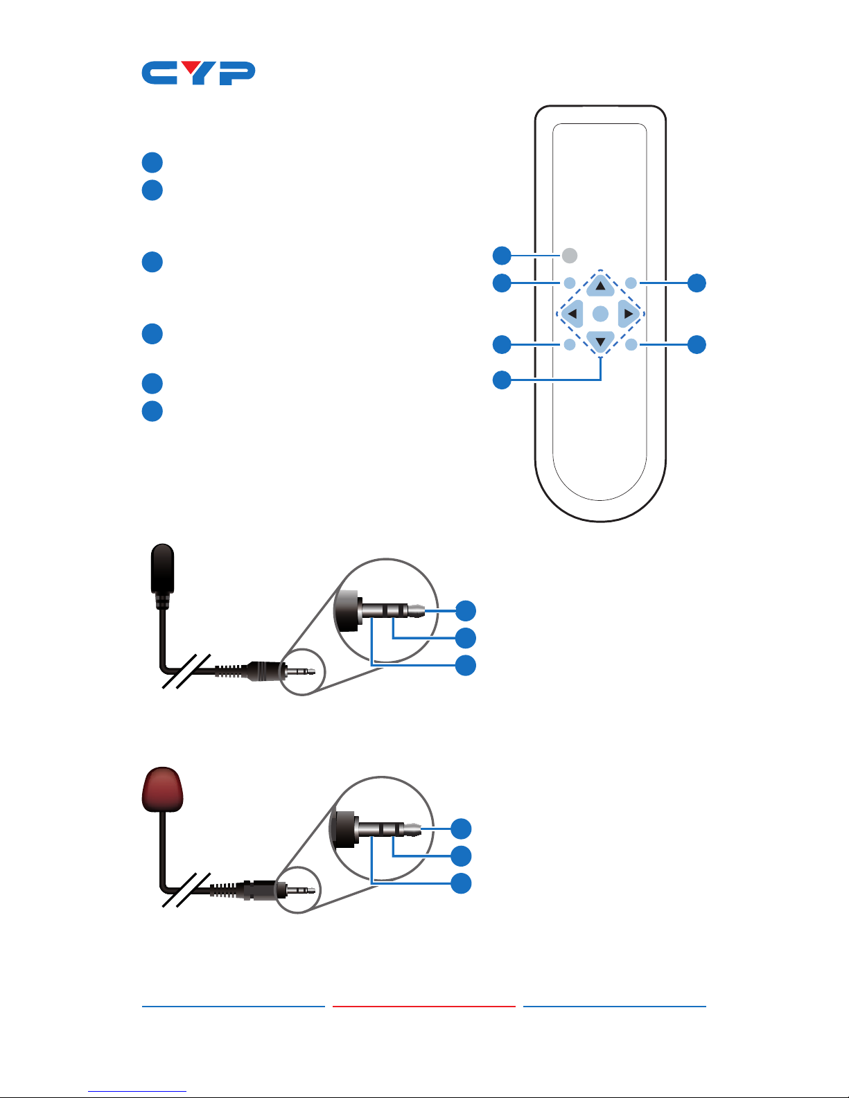
5IR Blaster: Connect the supplied IR Blaster cable for IR signal
transmission. Place the IR Blaster in direct line-of-sight of the
equipment to be controlled.
6IR Extender: Connect to the supplied IR Receiver cables for IR
signal reception. Ensure that remote being used is within the direct
line-of-sight of the IR Extender.
7CAT5e/6/7 IN: Connect to the Transmitter unit with a Single
CAT5e/6 cable for receiving all data signals.
MODE LED: This LED will illuminate when the power is connected.
LINK LED: This LED will illuminate when connected to a Transmitter
unit that is connected to a source that is outputting a signal.

5
6.3 Remote Control
1INPUT: Not functional.
2EXIT: Press this button to exit the menu
or escape the current selection under
OSD.
3MENU: Press this button to exit the menu
or the current selection in the on-screen
menu.
4RESET: Press this button to return the
device to the factory default settings.
5AUTO ADJUST: Not functional.
6 OK & ▲▼◄►: Press 'OK' to conrm the
selection or use the directional buttons
to navigate the on-screen menus.
6.4 IR Cable Pin Assignment
3
1
3
1
2
2
Power
IR Blaster Signal
NC
IR Signal
Power
Ground
IR Extender
IR Blaster
CR-128
OK
INPUT
EXIT MENU
RESET AUTO
ADJUST
1
2
4
6
3
5

6
6.5 RS-232 Pin Denitions
PIN DEFINE TX / RX
1N/C
2TxD/RxD
3RxD/TxD
4NC
5GND
6NC
7NC
8NC
9NC
Baud Rate: 9600bps
Data bit: 8 bits
Parity: None
Flow Control: None
Stop Bit: 1

7
6.6 RS-232 Commands
COMMAND DESCRIPTION
S OUTPUT 0~25 0=Native 12=1600×1200
1=640×480 13=1920×1080
2=800×600 16=1920×1200
3=1024×768 17=480p
5=1360×768 18=720p@60
6=1280×720 19=1080p@60
7=1280×800 20=1080i@60
8=1280×1024 22=576p
9=1440×900 23=720p@50
10=1400×1050 24=1080p@50
11=1680×1050 25=1080i@50
R OUTPUT Reports the numerical equivalent for the
OUTPUT setting (as listed above)
S SIZE 0~6 0=OVERSCAN 4=LETTER BOX
1=FULL 5=UNDER 2
2=BEST FIT 6=UNDER 1
3=PAN SCAN
R SIZE Reports the numerical equivalent for the SIZE
setting (as listed above)
S CONTRAST 0~60 Sets the numerical value for the CONTRAST
setting (0-60)
R CONTRAST Reports the numerical value for the CONTRAST
setting (0-60)
S BRIGHTNESS 0~60 Sets the numerical value for the BRIGHTNESS
setting (0~60)
R BRIGHTNESS Reports the numerical value for the BRIGHTNESS
setting (0~60)
S HUE 0~60 Sets the numerical value for the setting (0~60)
R HUE Reports the numerical value for the setting
(0~60)

8
COMMAND DESCRIPTION
S SATURATION 0~60 Sets the numerical value for the SATURATION
setting (0~60)
R SATURATION Reports the numerical value for the SATURATION
setting (0~60)
S SHARPNESS 0~30 Sets the numerical value for the SHARPNESS
setting (0~30)
R SHARPNESS Reports the numerical value for the SHARPNESS
setting (0~30)
S NR 0~3 0=OFF 2=MIDDLE
1=LOW 3=HIGH
R NR Reports the numerical equivalent for the NOISE
REDUCTION setting (as listed above)
S AUDIO DELAY 0~3 0=OFF 2=110ms
1=40ms 3=150ms
R AUDIO DELAY Reports the numeric equivalent for AUDIO
DELAY setting (as listed above)
S AUDIO MUTE 0/1 0=ON 1=MUTE
R AUDIO MUTE Reports the numeric equivalent for AUDIO MUTE
setting (as listed above)
S KEY LOCK 0/1 0=ENABLE 1=DISABLE
R KEY LOCK Reports the numeric equivalent for KEY LOCK
setting (as listed above)
FW Checks the FIRMWARE version
S RESET 1 Sets the numerical equivalent for the RESET
setting (as left)
Note:
1. RS-232 commands will not execute unless followed with carriage
return and LF (Line Feed).
2. Commands are not case-sensitive.
3. Resolutions 1~16 are RGB encoded and 17~25 are YUV encoded.
4. Digital audio supports LPCM 2CH only, please ensure the source
input audio is set to send LPCM 2CH audio in order to avoid
unwanted audio noise.

9
6.7 OSD Menu
1ST LAYER 2ND LAYER 3RD LAYER
DISPLAY OUTPUT Native
640x480 60
800x600 60
1024x768 60
1360x768 60
1280x720 60
1280x800 60
1280x1024 60
1440x900 60
1400x1050 60
1680x1050 60
1600x1200 60
1920x1080 60
1920x1200 60
720x480P 60
1280x720P 60
1920x1080I 60
1920x1080P 60
720x576P 50
1280x720P 50
1920x1080I 50
1920x1080P 50

10
1ST LAYER 2ND LAYER 3RD LAYER
SIZE SIZE OVER SCAN
FULL
ASPECT RATIO
PAN SCAN
LETTER BOX
UNDER 2
UNDER 1
MODE INFO INFO
ON
OFF
COLOR R
G
B
R OFFSET
G OFFSET
B OFFSET
CONTRAST 0~60
BRIGHTNESS 0~60
HUE 0~60
SATURATION 0~60
SHARPNESS 0~60
NR OFF
LOW
MIDDLE
HIGH
AUDIO VOLUME 0~100
DELAY OFF
40mS
110mS
150mS

11
1ST LAYER 2ND LAYER 3RD LAYER
SOUND ON
MUTE
SETUP FACTORY RESET NO
YES
KEY LOCK OFF
ON
INFORMATION INPUT
OUTPUT
REVISION
Note: Items in Bold are the default setting.
6.8 Input Resolutions Support
INPUT RESOLUTION HDMI
480i/576i
480p/576p
720p@50/60 Hz
1080i@50/60 Hz
1080p@50/60 Hz
VGA@60/72/75 Hz
SVGA@56/60/72/75 Hz
XGA@60/70/75 Hz
SXGA@60/75 Hz
UXGA@60 Hz
1280×800@60 Hz
1680×1050@60 Hz (RB)
1920×1080@60 Hz

12
7. CONNECTION DIAGRAM
XGA
MENUENTER
-
+
720P
SERVICE HDMI OUT
OPTICAL OUT
IR
Blaster
IR
Extender
CAT5e/6 IN
MODE
LINK
LANRS232 OUT
DC 24V
POWER
1.5m
60°
1.5m
60°
RS-232 In
LAN
HDMI In
HDMI to CAT5e/6 with LAN/IR/RS232
Transmitter
7m3m 3m
60°
m
m
m
60°
Digital Audio
Output (Optical)
RS-232 Control System
RS-232 Device to
be Controlled
Power Supply
Router with Internet
Connection
DVD Player
Smart TV
AV Receiver
HDMI
Output
HDMI
Input
LAN
LAN
RS-232
RS-232
IR Blaster
IR Blaster
IR Extender
IR Extender
Compatible PoE
Transmitter Unit
CAT5e/6/7
Cable (100m)

13
8. SPECIFICATIONS
8.1 Technical Specications
Ethernet Speed 100 Mbps
Input Video Bandwidth 300MHz / 10.2Gbps
Output Video Bandwidth 165MHz / 1.65Gbps
Input Ports 1×CAT5e/6/7, 1×IR Extender
Output Ports 1×HDMI, 1×IR Blaster, 1×Optical,
1×RS-232, 1×LAN
CAT5e/6/7 Output Cable
Distance
Up to 100 Meters
HDMI Resolutions Support HD: Up to 1080p@60 Hz
PC: Up to WUXGA (RB)
Audio Sampling Rate Up to 48 kHz or LCPM 2CH
CAT5e/6/7 Resolutions
Support
HD: Up to 1080p@60 Hz
PC: Up to WUXGA (RB)
IR Frequency 30~50 kHz
ESD Protection Human body model:
±8kV (air-gap discharge)
±4kV (contact discharge)
Dimensions 145 mm (W)×192 mm (D)×30 mm (H)/
Jacks Excluded
145 mm (W)×202.75 mm (D)×30
mm(H)/Jacks Included
Weight 608 g
Chassis Material Aluminum
Color Black
Operating Temperature 0 ˚C~40 ˚C / 32 ˚F~104 ˚F
Storage Temperature −20 ˚C ~ 60 ˚C / −4 ˚F ~ 140 ˚F
Relative Humidity 20 ~ 90 % RH (non-condensing)
Power Consumption 14 W

14
8.2 CAT5e/6/7 Cable Specication
Cable Type Range Pixel Clock
Rate
Video Data
Rate
Supported Video
CAT5e/6/7 100 m ≤225 MHz ≤5.3 Gbps
(HD Video)
Up to 1080p, 60 Hz,
36 bits, 3D (data
rates lower than 5.3
Gbps or below 225
MHz TMDS clock).
9. ACRONYMS
ACRONYM COMPLETE TERM
CAT5e Category 5 Cable
CAT6 Category 6 Cable
CAT7 Category 7 Cable
HDMI High-Denition Multimedia Interface
IR Infrared
WUXGA (RB) Widescreen Ultra Extended Graphics Array (Reduce
blanking)

Home page: http://www.cypress.com.tw
CYPRESS TECHNOLOGY CO., LTD
20130624 MPM-CH517RXHS
Table of contents
Other CYP Receiver manuals

CYP
CYP IP-7050RX-TG User manual

CYP
CYP PU-305BDA-TX User manual

CYP
CYP CH-1106TX & RX User manual

CYP
CYP PRO-F21RX User manual

CYP
CYP CWHDI-Tx User manual

CYP
CYP CH-2603RX User manual

CYP
CYP PUV-3050RX-UA User manual

CYP
CYP CH-1604TXD User manual

CYP
CYP HDMI Over CAT5 User manual

CYP
CYP CH-2527TXV User manual