CYP CDPS-P314EDC User manual

Operation Manual
Operation Manual
HDMI over H.264/H.265 Transceiver
CDPS-P314EDC

®
registered trademarks of HDMI licensing Administrator, Inc.

DISCLAIMERS
The information in this manual has been carefully checked and is believed
to be accurate. Cypress Technology assumes no responsibility for any
infringements of patents or other rights of third parties which may result from
its use.
Cypress Technology assumes no responsibility for any inaccuracies that
may be contained in this document. Cypress also makes no commitment to
update or to keep current the information contained in this document.
Cypress Technology reserves the right to make improvements to this
document and/or product at any time and without notice.
COPYRIGHT NOTICE
No part of this document may be reproduced, transmitted, transcribed,
stored in a retrieval system, or any of its part translated into any language
or computer le, in any form or by any means—electronic, mechanical,
magnetic, optical, chemical, manual, or otherwise—without express written
permission and consent from Cypress Technology.
© Copyright 2018 by Cypress Technology.
All Rights Reserved.
TRADEMARK ACKNOWLEDGMENTS
All products or service names mentioned in this document are trademarks of
the companies with which they are associated.

SAFETY PRECAUTIONS
Please read all instructions before attempting to unpack, install or operate
this equipment and before connecting the power supply. Please keep the
following in mind as you unpack and install this equipment:
• Always follow basic safety precautions to reduce the risk of re,
electrical shock and injury to persons.
• To prevent re or shock hazard, do not expose the unit to rain, moisture
or install this product near water.
• Never spill liquid of any kind on or into this product.
• Never push an object of any kind into this product through any openings
or empty slots in the unit, as you may damage parts inside the unit.
• Do not attach the power supply cabling to building surfaces.
• Use only the supplied power supply unit (PSU). Do not use the PSU if it
is damaged.
• Do not allow anything to rest on the power cabling or allow any weight to
be placed upon it or any person walk on it.
• To protect the unit from overheating, do not block any vents or openings
in the unit housing that provide ventilation and allow for sucient space
for air to circulate around the unit.
• Please completely disconnect the power when the unit is not in use to
avoid wasting electricity.
VERSION HISTORY
REV. DATE SUMMARY OF CHANGE
RDV1 2020/06/02 Preliminary release

CONTENTS
1. Introduction...................................................... 1
2. Applications ..................................................... 1
3. Package Contents ........................................... 2
4. System Requirements..................................... 2
5. Features............................................................ 3
6. Operation Controls and Functions ................ 4
6.1 Front Panel.................................................. 4
6.2 Rear Panel................................................... 5
6.3 IR Cable Pinouts.......................................... 6
6.4 RS-232 Pinout and Defaults........................ 6
6.5 OSD Menu................................................... 7
6.6 WebGUI Control ........................................ 12
6.6.1 Preview Tab...................................... 14
6.6.2 System Tab....................................... 15
6.6.3 Settings Tab...................................... 22
6.6.4 Transmitter Tab (Encoder Mode)...... 25
6.6.5 Receiver Tab (Decoder Mode) ......... 30
6.6.6 Recording Tab (Encoder Mode) ....... 35
6.7 Telnet Control ............................................ 38
6.8 Telnet Commands...................................... 38
7. Connection Diagram ..................................... 55
8. Specications ................................................ 56
8.1 Technical Specications ............................ 56
8.2 Video Specications .................................. 57
8.3 Audio Specications .................................. 59
8.3.1 Digital Audio ..................................... 59
8.3.2 Analog Audio .................................... 59
8.4 Cable Specications.................................. 60
9. Acronyms ....................................................... 61

1
1. INTRODUCTION
As an increasing number of people share videos across the Internet, a
simple to congure and easy to use transceiver that supports native H.265/
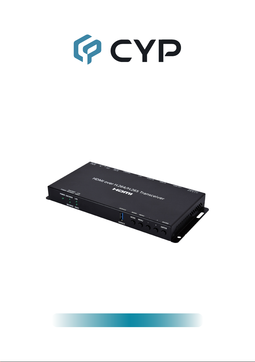
H.264 encoding and decoding will be indispensable. This HDMI over H.264/
H.265 Transceiver, in Encoder mode, can encode any standard UHD HDMI
source and generate a high quality, low latency, video stream for distribution
over standard Gigabit Ethernet networks while also supporting archival
storage. In Decoder mode it can decode any standard H.264/H.265 video
stream for output over its HDMI output and can support resolutions up to
4K@60Hz.
This transceiver’s exible settings allow streaming bitrates from 1,000 to
20,000kbps and provides controls that let the user to adjust video quality
easily. This unit also supports the simultaneous distribution of both unicast
and multicast streams of the HDMI source allowing for a exible mixture of
one-to-one and one-to-many distribution styles, as each network section
allows or requires. In Decoder mode, output supports a variety of formats
allowing for the creation of advanced presentations such as multiview
displays and video walls. Additionally, the independent extension of CEC, IR,
RS-232 and audio is provided. Integrated support for all of the most common
security protocols including HTTPS, SSH, and 802.1X is also provided to
ensure that your streams only reach their intended audience and that your
login connection is secure.
This transceiver can be powered locally, or via the connected Ethernet
switch if it supports the IEEE 802.3at PoE (Power over Ethernet) standard.
Basic unit conguration is provided via front panel buttons with an On Screen
Display (OSD) menu and streaming conguration controls are via WebGUI
and Telnet. Enhanced conguration and control is available when combined
with the IP Master Controller unit.
2. APPLICATIONS
• Webcasting & Social Media Broadcasting
• Live Event Streaming
• Video on Demand Streaming
• Live recording and storage
• Distributed video matrix system
• Distributed video wall system

2
3. PACKAGE CONTENTS
• 1× HDMI over H.264/H.265 Transceiver
• 1× 12V/3A DC Power Adapter (Optional)
• 1× Power Cord (Optional)
• 1× 5-pin Terminal Block
• 1× 3-pin Terminal Block
• 1× Shockproof Feet (Set of 4)
4. SYSTEM REQUIREMENTS
• HDMI source equipment such as a media player, video game console, PC,
or set-top box.
• HDMI receiving equipment such as an HDTV, monitor or audio amplier.
• The use of Premium High Speed HDMI cables, and industry standard
Cat.6, Cat.6A or Cat.7, is highly recommended.
• Available streaming server destination such as YouTube or Facebook or a
recording storage target such as a NAS or USB thumb drive.
• To view RTSP streams directly on the local network, RTSP stream
compatible video player software (such as VLC Media Player or PotPlayer)
must be used.
Note: For security reasons it is strongly advised to maintain a rewall
between this unit and the internet.

3
5. FEATURES
• HDMI 2.0 and DVI 1.0 compatible
• HDCP 1.x and HDCP 2.2 compliant
Note: HDCP encrypted sources cannot be streamed over the Internet or
recorded and will be blacked out
• 1 HDMI input and 1 HDMI output
• Video, audio, and control transmission over in unicast (point-to-point) and
multicast (single-to-many) modes
• In transmitter mode, generates streams using H.264 or H.265
• Supports multiple transport protocols: RTSP, RTP, RTMP, and FLV
• Low latency streaming (1080P@60 100~160ms, 4K@30 200~250ms)
• Supports extension of CEC, RS-232 and IR over Ethernet
• Supports independent recording to a user-determined destination
• Recorded video can be stored on locally connected USB storage (FAT or
exFAT format) or to a designated network drive supporting NFS or CIFS
• Supports encrypting streams using 802.1X security (PEAP, TLS, TTLS)
• Supports secure logins using HTTPS and SSH
• Independent breakaway A/V matrix switching (requires optional IP Master
Controller)
• Video wall generation
• Multi-view compositing (requires optional IP Master Controller)
• May be powered directly by PoE when connected to a Gigabit Ethernet
switch that provides PoE (802.3at)
• Basic unit conguration is provided via front panel buttons with an OSD
menu and streaming conguration controls are via WebGUI and Telnet
• Supports the use of an external control center (IP Master Controller) to
provide expanded functionality (Contact your authorized dealer for more
information)

4
6. OPERATION CONTROLS AND FUNCTIONS
6.1 Front Panel
108&3 &/$0%&3 -"/ .0%& .&/6 &/5&3
%&$0%&3 7*%&0 4&37*$&
765
4
321
1POWER LED: This LED will illuminate to indicate the unit is on and
receiving power.
2ENCODER/DECODER LEDs: These LEDs will illuminate to indicate if
the unit is in Encoder or Decoder mode.
3VIDEO LED: This LED will illuminate when the currently selected video
source is connected and active.
4LAN LED: This LED will illuminate when a live Ethernet connection is
detected.
5SERVICE Port (USB 3.0 Type-A): Attach a standard USB thumb drive
or external hard drive for storage of recorded video. (Optional)
Note: Storage media must be formatted as FAT32 or exFAT. Video les
are stored in *.mp4 format. Up to 1A is available to power an external
USB device.
6MODE button: Press and hold for 2 seconds to toggle between the
Encoder and Decoder operational modes.
Note: After changing modes the unit will automatically reboot.
7MENU Button: Press to enter the OSD menu, or to back out from menu
items.
- (MINUS)/+ (PLUS) Buttons: Press to move up and down or adjust
selections within OSD menus.
Note: In Decoder mode, pressing and holding the + (PLUS) button will
force the output to switch to 1080p60.
ENTER Button: Press to conrm a selection within the OSD or to go
deeper into a menu item.

5
6.2 Rear Panel
L+ L- GR+R-
AUDIO OUT HDMI OUT
DC 12V
RS-232
LAN
HDMI IN AUDIO IN LAN(POE) IR
INOUT
TX RX
4 5 6 7 8321
1AUDIO OUT 5-pin Terminal Block: Connect to powered speakers or an
amplier for analog stereo audio output.
Note: Only LPCM 2.0 sources are supported.
2HDMI OUT Port: Connect to an HDMI TV, monitor, or amplier for digital
video and audio output.
3HDMI IN Port: Connect to HDMI source equipment such as a media
player, game console, or set-top box.
4AUDIO IN Port: Connect to the analog stereo output of a device such as
an audio player or PC.
5LAN Ports: Both ports are linked by an internal 2 port switch. Connect
either of these ports to a network switch, router, PC, or another
transceiver for transmission/reception of streamed video as well as to
control the unit via Telnet or WebGUI.
Note: This unit can be powered via PoE when the LAN(PoE) port is
directly connected to a Gigabit Ethernet switch that provides PoE
(802.3at).
6RS-232 3-pin Terminal Block: Connect to a PC, laptop, or serial
controllable device for the extension of RS-232 signals.
7IR OUT Port: Connect to an IR Blaster to transmit IR signals from a
connected transceiver to devices within direct line-of-sight of the IR
Blaster.
IR IN Port: Connect to an IR Extender to receive local IR control signals
and extend them to devices located near a connected transceiver.
Ensure that the remote being used is within direct line-of-sight of the IR
Extender.
8DC 12V Port: Plug the 12V DC power adapter into this port and connect
it to an AC wall outlet for power.

6
6.3 IR Cable Pinouts
IR Blaster
Cabl
e
1
2
3
Infrared
Power
Not Use
d
IR Extender
Cabl
e
1
2
3
Infrared
Power
Ground
6.4 RS-232 Pinout and Defaults
Serial Port Default Settings
Baud Rate 19200
Data Bits 8
Parity Bits None
Stop Bits 1
Flow Control None
1
2
3
RxD
GND
TxD
3-pin
Terminal Block

7
6.5 OSD Menu
All functions of this unit can be controlled by using the OSD (On Screen
Display) which is activated by pressing the MENU button on the front of the
unit. Use the + (PLUS), − (MINUS), and ENTER buttons to navigate the OSD
menu. Press the MENU button to back out from any menu item and then
press it again to close the menu.
MAIN MENU
Video
Audio
OSD
Ethernet
Factory
Information
The individual functions of the OSD will be introduced in the following
section. Items marked in BOLD are the factory default settings.

8
VIDEO
2ND LEVEL 3RD LEVEL
Decoder Video Source STREAMING
HDMI
Output Resolution NATIVE
Auto
1280x720p50
1280x720p60
1920x1080p30
1920x1080p50
1920x1080p60
3840x2160p25
3840x2160p30
3840x2160p50
3840x2160p60
HDMI EDID COPY SINK
FHD 2Ch
UHD 2Ch
UHD+ 2Ch
User
1) Decoder Video Source: Select the input source, between Streaming or
local HDMI, to output to the connected display.
Note: Only available in decoder mode.
2) Output Resolution: Select the output resolution to use for the currently
selected source. Selecting “Native” will attempt to output at the native
resolution requested by the connected display. Selecting “Auto” will
output using the current source’s resolution.
Note: Only available in decoder mode.
3) HDMI EDID: Select the EDID to use with the local HDMI input.

9
AUDIO
2ND LEVEL 3RD LEVEL
HDMI Mute OFF
On
Line Out Mute OFF
On
Line Out Volume 0~100 (80)
1) HDMI Mute: Enable or disable muting the HDMI output’s audio.
2) Line Out Mute: Enable or disable muting the analog audio output.
3) Line Out Volume: Set the volume level of the analog audio output.
OSD
2ND LEVEL 3RD LEVEL
H Position 0~60 (30)
V Position 0~60 (30)
Timer OFF
5s
10s
15s
20s
25s
30s
35s
40s
45s
50s
55s
60s
Transparency 0~7 (0)

10
OSD
2ND LEVEL 3RD LEVEL
Display 10S
5s
On
O
1) H/V Position: Set the horizontal and vertical position of the OSD menu.
2) Timer: Set how long to wait before automatically closing the OSD menu
if there is no user activity. The timeout can be set to up to 60 seconds, or
disabled completely.
3) Transparency: Set the transparency level of the OSD menu’s
background. The available range is from 1 (fully opaque) to 7 (fully
transparent).
4) Display:
Set how long to display the OSD information window. Selecting
“O” will disable the OSD information window. Selecting “On” will always
display the OSD information window.
ETHERNET
2ND LEVEL 3RD LEVEL 4TH LEVEL
IP Mode Static IP
DHCP
Setup Static IP Static IP 0~255 (192)
0~255 (168)
0~255 (1)
0~255 (50)
Netmask 0~255 (255)
0~255 (255)
0~255 (0)
0~255 (0)
Gateway 0~255 (192)
0~255 (168)
0~255 (1)
0~255 (254)

11
ETHERNET
2ND LEVEL 3RD LEVEL 4TH LEVEL
IP [Current IP Address]
MAC [Unit’s MAC Address]
1) IP Mode: Set the unit to Static or DHCP mode. When DHCP mode is
selected, all IP address information will be assigned automatically by the
local DHCP server. When Static is selected, the IP address, netmask and
gateway must be set manually using the “Setup Static IP” menu.
Note: The unit is set to DHCP by default.
2) Static IP Setting: The unit’s static IP address, netmask, and gateway
address can be set here. Press the “Enter” button to begin editing the
address and use the “+” and “-” buttons to adjust each value. Press the
“Enter” button to store the current number segment and move to the next
segment.
Note: These values can be set even when the unit is in DHCP mode, but
they will not be used until the mode is changed to Static IP.
3) IP: Displays the unit’s current IP address.
4) MAC:
Displays the unit’s MAC address.
FACTORY
2ND LEVEL 3RD LEVEL
Reset
1) Reset: Pressing the “Enter” button will cause a reset conrmation
window to pop up. Press the “Enter” button again, within 10 seconds, to
reset all of the unit’s settings back to their factory defaults.
INFORMATION
2ND LEVEL 3RD LEVEL
SN [Unit’s Serial Number]
Version [Current Firmware Version]
1) Information: This screen displays information about the unit’s serial
number and the current rmware version.

12
6.6 WebGUI Control
• Device Discovery
Please obtain the “Device Discovery” software from your authorized dealer
and save it in a directory where you can easily nd it.
Connect the unit and your PC/Laptop to the same active network and
execute the “Device Discovery” software. Click on “Find Devices on Internet”
and a list of devices connected to the local network will show up indicating
their current IP address.
Note: This unit defaults to DHCP mode. The current IP address can be
veried using the OSD if the Device Discovery software is not available.
By clicking on one of the listed devices you will be presented with the
network details of that particular device.
1) IP Mode: If you choose, you can alter the static IP network settings for
the device, or switch the unit into DHCP mode to automatically obtain
proper network settings from a local DHCP server. To switch to DHCP
mode, please select DHCP from the IP mode drop-down, then click “Save”
followed by “Reboot”.
2) WebGUI Hotkey: Once you are satised with the network settings, you
may use them to connect via Telnet or WebGUI. The network information
window provides a convenient link to launch the WebGUI directly.

13
• WebGUI Overview
After connecting to the WebGUI’s address in a web browser, the login screen
will appear. Please enter the appropriate user name and password then click
“Submit” to log in.
Note: The default user name and password is “admin”.
On the left side of the browser you will see one of the two following menu
tab sets, depending on if the unit is in transmitter or receiver mode, where
all primary functions of the unit are controllable via the built in WebGUI. The
individual functions will be introduced in the following sections.
Clicking the red “Logout” tab will automatically log the currently connected
user out of the WebGUI and return to login page.

14
6.6.1 Preview Tab
In Encoder mode, this tab provides a limited framerate preview window of
the primary video stream channel generated by the unit. At the bottom of the
tab a connection address for video stream 1 is displayed in the format: “rtsp://
x.x.x.x/stream” (x.x.x.x= the unit’s current IP address). When 3rd party video
player software with RTSP streaming support is used to view streams from
this unit, this is the URL that should be used to connect. To view streaming
channel 2, change “stream” in the address to “stream2”.
In Decoder mode, this tab will display the video stream currently being
received and output. If the unit is in video wall mode, only this unit’s portion
of the video will be displayed.
Note: The primary stream’s conguration is set on the video prole section of
the source unit’s transmitter tab.
1) FPS:
The framerate of the preview window can be set from 1 to 10
frames per second. Click “Save” to save and activate the new preview
frame rate.

15
6.6.2 System Tab
This tab provides access to system conguration options including
device information and network conguration, rmware update, security
conguration, and account conguration.
1) Info: This section provides information and control over the unit’s
operational mode, device name, and network conguration. Options
for updating the rmware, saving/restoring the unit’s conguration, and
performing a factory reset is also provided.
Device Info:
Locate Device: Clicking this switch will enable or disable the unit’s
“Hello” mode. When enabled it will cause the unit’s current mode LED
to immediately begin ashing on the front of the unit to make it easy to
nd.
Device Name: A custom name to identify the unit can be set here.
After changing the name, press the enter key to store the change.
Note: The default device name is the same as the hostname.
Hostname: Displays the unit’s network hostname.
Note: The hostname is based on the unit’s MAC address to avoid
potential network conicts and cannot be changed.
S/N: Displays the unit’s serial number.
Mode: Click the button to switch the unit between Encoder and
Decoder mode. After changing modes the unit will reboot.
Video Input Timing (Encoder Mode Only): Displays the resolution of
the current HDMI video source.
Table of contents
Other CYP Transceiver manuals
Popular Transceiver manuals by other brands

Vertex Standard
Vertex Standard HX750S Alignment Guide

Kenwood
Kenwood TS-450S instruction manual

Alinco
Alinco DR-135T MkII instruction manual

Technisonic Industries Limited
Technisonic Industries Limited TDFM-136 Quick reference guide

Standard
Standard C430 operating instructions

AES
AES 7350 installation manual