CYP AVX-501C-TR User manual

AVX-501C-TR
AVX over Cat. - UHD+ 2x1 HDMI/DP to HDMI Bi-
directional Transceiver W/HID USB
OPERATION MANUAL


DISCLAIMERS
The information in this manual has been carefully checked and is
believed to be accurate. CYP (UK) Ltd assumes no responsibility for any
infringements of patents or other rights of third parties which may result
from its use.
CYP (UK) Ltd assumes no responsibility for any inaccuracies that may be
contained in this document. CYP (UK) Ltd also makes no commitment to
update or to keep current the information contained in this document.
CYP (UK) Ltd reserves the right to make improvements to this document
and/or product at any time and without notice.
COPYRIGHT NOTICE
No part of this document may be reproduced, transmitted, transcribed,
stored in a retrieval system, or any of its part translated into any language
or computer file, in any form or by any means—electronic, mechanical,
magnetic, optical, chemical, manual, or otherwise—without express
written permission and consent from CYP (UK) Ltd.
© Copyright 2021 by CYP (UK) Ltd.
All Rights Reserved.
Version 1.1
TRADEMARK ACKNOWLEDGMENTS
All products or service names mentioned in this document may be
trademarks of the companies with which they are associated.

SAFETY PRECAUTIONS
Please read all instructions before attempting to unpack, install or operate
this equipment and before connecting the power supply. Please keep the
following in mind as you unpack and install this equipment:
• Always follow basic safety precautions to reduce the risk of fire,
electrical shock and injury to persons.
• To prevent fire or shock hazard, do not expose the unit to rain,
moisture or install this product near water.
• Never spill liquid of any kind on or into this product.
• Never push an object of any kind into this product through any
openings or empty slots in the unit, as you may damage parts inside
the unit.
• Do not attach the power supply cabling to building surfaces.
• Use only the supplied power supply unit (PSU). Do not use the PSU if
it is damaged.
• Do not allow anything to rest on the power cabling or allow any
weight to be placed upon it or any person walk on it.
• To protect the unit from overheating, do not block any vents or
openings in the unit housing that provide ventilation and allow for
sufficient space for air to circulate around the unit.
• Please completely disconnect the power when the unit is not in use
to avoid wasting electricity.
VERSION HISTORY
REV. DATE SUMMARY OF CHANGE
RDV1 2021/10/14 Preliminary release

CONTENTS
1. Introduction..................................................1
2. Applications ..................................................1
3. Package Contents .........................................1
4. System Requirements ..................................2
5. Features.........................................................2
6. Operation Controls and Functions ..............3
6.1 Front Panel.............................................................3
6.2 Rear Panel...............................................................4
6.3 IR Cable Pinouts ...................................................6
6.4 RS-232 Pinout and Defaults.............................6
6.5 OSD Menu..............................................................7
6.6 Basic AV Extension ........................................... 14
6.6.1 Point-to-Point (One Way).................... 14
6.6.2 Point-to-Point (Bi-directional)........... 14
7. Connection Diagram ..................................15
8. Specifications..............................................16
8.1 Technical Specifications ................................. 16
8.2 Video Specifications......................................... 17
8.3 Audio Specifications........................................ 19
8.3.1 Digital Audio ........................................... 19
8.3.2 Analogue Audio..................................... 20
8.4 Cable Specifications ........................................ 21
9. Acronyms.....................................................22

1
1. INTRODUCTION
This Transceiver is designed for high-quality, IP routable, AV extension
with minimum latency. Every Transceiver is capable of simultaneous bi-
directional AV extension, enhancing the exibility of any installation. By
using a sophisticated ultra-light compression scheme (lossless for most
content) it’s a great solution for extending 4K audio/video streams (HDMI
or DisplayPort) and data. Advanced HDMI content such as HDR (High
Dynamic Range), 10-bit colour and multi-channel HD Bitstream audio
can be transmitted in pass-through mode. The use of high quality 10
Gigabit Ethernet ports and Cat.6A or better cable allows for point-to-point
transmission distances up to 100m. Multiple control and data signals may
also be transmitted along with the audio and video, including IR, RS-232,
USB (HID only), and Ethernet.
The built-in EDID and HDCP management functionality enables the unit
to t into every situation. Basic conguration of the unit can be achieved
via front panel buttons with an OSD (On-Screen Display).
2. APPLICATIONS
Video, Audio, LAN, IR, and USB (HID only) over 10GbE extension
Point-to-Point Secure Video Conferencing
Hotel or convention center display
Remote KVM system control
3. PACKAGE CONTENTS
1× UHD+2×1 HDMI/DP to HDMI Bi-directional AV over IP Transceiver
1× 12V/3A DC Power Adapter
1× Power Cord
1× Operation Manual

2
4. SYSTEM REQUIREMENTS
HDMI or DisplayPort source equipment such as a media player, video
game console, PC, or set-top box
HDMI receiving equipment such as an HDTV, monitor, or audio
amplifier
Analogue audio receiving equipment such as headphones, an audio
amplifier, or powered speakers
The use of Premium High Speed HDMI cables, and industry standard
Cat.6A, or Cat.7 Ethernet cable is required.
5. FEATURES
HDMI 2.0 and DVI 1.0 compatible
HDCP 2.2 and HDCP 1.x compliant
Transceiver with support for simultaneous bi-directional AV signal
extension
1 HDMI and 1 DisplayPort input
1 HDMI output
1 analogue stereo input & 1 analogue stereo output
2 USB (Type-A) ports (HID support only) and 1 USB 2.0 (Mini-B) port
Ultra-light compression, lossless for most content
Extension up to 100m in Point-to-Point mode (with Cat.6A cable)
Supports pass-through of 10/12-bit HDR sources
Supports pass-through of audio formats including LPCM (up to 8
channels), Bitstream and HD Bitstream from HDMI or DP sources
Bi-directional AV, IR, RS-232, USB (HID only), and Ethernet extension
Basic configuration via front panel buttons with an OSD
Supports the use of an external control center (IP Master Controller) or
control software to make adjustments to some functionality (Contact
your authorised dealer for more information)

3
6. OPERATION CONTROLS AND FUNCTIONS
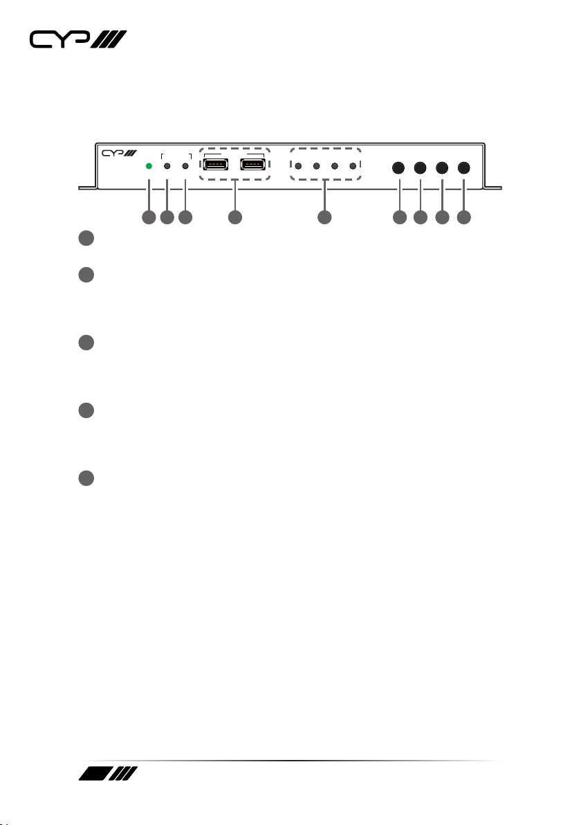
6.1 Front Panel
POWER SOURCE GbE VIDEO LINK USB MENU + ENTER
INFO
-
LINK USB
TR
HID USB
1 2 3 4 5 6 7 8 9
AVX-501C-TR
1POWER LED: This LED will illuminate to indicate the unit is on and
receiving power.
2SOURCE T LED: The illumination of this LED indicates which AV input
is currently selected to be the source transmitted as an AV over IP
stream. Green indicates the local HDMI input, amber indicates the
local DisplayPort input, o indicates the incoming AVoIP stream.
3SOURCE R LED: The illumination of this LED indicates which AV input
is currently selected as the source to be output over the local HDMI
output. Green indicates the local HDMI input, amber indicates the
local DisplayPort input, o indicates the incoming AVoIP stream.
4HID USB (Type-A) Ports: Connect directly to standard USB human
interface devices such as a mouse or keyboard to extend their USB
functionality to the currently active/routed transceiver with an active
host port.
5STATUS LED BLOCK:
GbE LED: This LED will illuminate and blink to indicate a live and
active connection on the local gigabit Ethernet port.
VIDEO LED: This LED indicates video streaming activity over the
CAT6A/7 port. It will illuminate green when a video signal is being
transmitted and amber when a video signal is being received.
When bi-directional video streaming is active, both colours will
illuminate. When no video is active the LED will remain off, even if
the streaming connection is valid.
LINK LED: These LEDs will illuminate and blink to indicate data
transmission and reception activity across the CAT6A/7 streaming
connection.
USB LED: This LED will illuminate when the unit’s USB ports have
successfully paired with the USB ports on another unit. This LED will
blink if the unit’s USB ports are not currently paired and in stand-by
mode.

4
6MENU Button: Press to enter the OSD menu, or to back out from
menu items.
Note: The OSD menu will be visible on the HDMI output of both connected
transceivers so it is recommended to adjust the OSD position on one unit
to avoid the menus overlapping.
7− (MINUS) Button: Press to move up or adjust selections within OSD
menus. When not in a menu, press to manually switch between“T”
source inputs.
8+ (PLUS) Button: Press to move up or adjust selections within OSD
menus. When not in a menu, press to manually switch between“R”
source inputs.
9ENTER/INFO Button: When inside an OSD menu, press to conrm a
selection or to go deeper into a menu item. When not in a menu, press
to activate the Information OSD.
6.2 Rear Panel
USB/SERVICELANRS-232IN
IRHDMI
OUTINOUTCAT6A/7DP ININOUT
DC 12V
AUDIO
TX RX
12 3 4 5 6 7 8 910
1HDMI OUT Port: Connect to an HDMI TV, monitor, or amplier for
digital video and audio output.
2HDMI IN Port: Connect to HDMI source equipment such as a media
player, game console, or set-top box.
3DP IN Port: Connect to DisplayPort source equipment such as a PC or
laptop.
4CAT6A/7 Port: Connect directly to a compatible transceiver for bi-
directional Point-to-Point extension.

5
5AUDIO PORTS:
OUT Port: Connect to powered speakers or an amplifier for stereo
analogue audio output.
IN Port: Connect to the stereo analogue output of a device such as
a CD player or PC.
Note: Audio is routed directly from the IN Port to the opposite
transceiver’s OUT Port.
6IR PORTS:
OUT Port: Connect to an IR Blaster to broadcast IR signals from a
connected transceiver to devices within direct line-of sight of the IR
Blaster.
IN Port: Connect to an IR Extender to receive IR control signals
and extend them to devices connected to a connected transceiver.
Ensure that the remote being used is within direct line-of-sight of
the IR Extender.
Note: Currently, only 38KHz IR signal extension is supported.
7RS-232 3-pin Terminal Block: Connect directly to a PC, laptop or
serial controllable device with a 3-pin adapter cable to extend the RS-
232 signal between transceivers.
8LAN Port: Connect to an Ethernet supporting device or to your local
network as appropriate to extend the network between transceivers.
9USB/SERVICE (Mini-B) Port: Connect directly to a standard USB host
such as a PC or laptop to extend their USB functionality to all currently
connected/routed USB devices.
Note: This port is only active when “USB Control Mode” is set to “Device”.
Only one of the two connected transceivers should be set as a USB Device
to avoid conflicts.
10 DC 12V Port: Plug the 12V DC power adapter into this port and
connect it to an AC wall outlet for power.

6
6.3 IR Cable Pinouts
IR Blaster
Cable
1
2
3
Infrared
Power
Not Used
IR Extender
Cable
1
2
3
Infrared
Power
Ground
6.4 RS-232 Pinout and Defaults
Serial Port Default Settings
Baud Rate 57600
Data Bits 8
Parity Bits None
Stop Bits 1
Flow Control None
1
2
3
RxD
GND
TxD
3-pin
Terminal Block
Note: The default Serial Port baud rate can only be changed by use of the
optional IP Master Controller or control software.

7
6.5 OSD Menu
All functions of this unit can be controlled by using the OSD (On Screen
Display) which is activated by pressing the MENU button on the front of
the unit. Use the + (PLUS), − (MINUS), and ENTER buttons to navigate the
OSD menu. Press the MENU button to back out from any menu item and
then press it again to close the menu.
MAIN MENU
OSD
EDID
HDCP
Device Setting
Information
Factory Setting
The individual functions of the OSD will be introduced in the following
section. Items marked in BOLD are the factory default settings.

8
OSD
2ND LEVEL 3RD LEVEL
Display Information ON
O
Information Timeout O
10~40 Sec (10 Sec)
Menu Timeout O
10~40 Sec (10 Sec)
Menu H Position 0~100 (10)
Menu V Position 0~100 (10)
1) Display Information: Enable or disable the Information OSD.
2) Information Timeout: Set the display timeout for the Information
OSD.
3) Menu Timeout: Set the display timeout for the OSD Menu.
4) Menu H Position: Set the horizontal position of the OSD Menu.
5) Menu V Position: Set the horizontal position of the OSD Menu.

9
EDID
2ND LEVEL 3RD LEVEL
HDMI EDID INTERNAL 1 (FHD 2CH)
Internal 2 (FHD MCh)
Internal 3 (UHD 2Ch)
Internal 4 (UHD MCh)
Internal 5 (UHD+ 2Ch)
Internal 6 (UHD+ MCh)
External A [HDMI Output]
External B [VoIP Output]
User 1
User 2
DP EDID INTERNAL 1 (FHD 2CH)
Internal 2 (FHD MCh)
Internal 3 (UHD 2Ch)
Internal 4 (UHD MCh)
Internal 5 (UHD+ 2Ch)
Internal 6 (UHD+ MCh)
External A [HDMI Out]
External B [VoIP Out]
User 1
User 2
VOIP EDID EXTERNAL A
1) HDMI EDID: Select the EDID to send to the unit’s HDMI input.
2) DP EDID: Select the EDID to send to the unit’s DisplayPort input.
3) VOIP EDID: The EDID provided to Video over IP connections is always
set to use the EDID from the unit’s local HDMI output.

10
This unit provides the following 6 default EDIDs:
Unit’s default EDIDs
FHD 2CH 1920×1080p@60Hz (4.95Gbps), 8-bit colour,
LPCM 2.0
FHD MCH 1920×1080p@60Hz (4.95Gbps), 8-bit colour,
LPCM 7.1 & Bitstream
UHD 2CH 3840×2160p@30Hz (10.2Gbps), 12-bit Deep Colour,
LPCM 2.0
UHD MCH 3840×2160p@30Hz (10.2Gbps), 12-bit Deep Colour,
LPCM 7.1 & Bitstream
UHD+ 2CH 3840×2160p@60Hz (18Gbps), 12-bit Deep Colour,
LPCM 2.0
UHD+ MCH 3840×2160p@60Hz (18Gbps), 12-bit Deep Colour,
LPCM 7.1 & Bitstream
Note: In some rare cases it is possible for custom or external EDIDs to
cause compatibility issues with certain sources. If this happens, it is
recommended to switch to one of the 6 default EDIDs for maximum
compatibility.

11
HDCP
2ND LEVEL 3RD LEVEL
HDMI HDCP Disable
Follow out
Follow in
FOLLOW API
DP HDCP Disable
Follow out
Follow in
FOLLOW API
VOIP HDCP FOLLOW IN
1) HDMI HDCP: Selects the HDCP logic to use with the HDMI input.
Follow In: The input supports up to the HDCP version required
by the connected source.
Follow Out: The input supports up to the HDCP version
supported by the connected display.
Disable: HDCP support is completely disabled.
Follow API: Uses the HDCP setting defined by the IP Master
Controller or control software.
Note: In a Point-to-Point configuration, “Follow API” will behave the
same as “Follow Out”, if the API hasn’t been manually redefined.
2) DP EDID: Selects the HDCP logic to use with the DisplayPort input.
Follow In: The input supports up to the HDCP version required
by the connected source.
Follow Out: The input supports up to the HDCP version
supported by the connected display.
Disable: HDCP support is completely disabled.
Follow API: Uses the HDCP setting defined by the IP Master
Controller or control software.
Note: In a Point-to-Point configuration, “Follow API” will behave the
same as “Follow Out”, if the API hasn’t been manually redefined.
3) VOIP EDID: The Video over IP HDCP behavior is always“Follow In”.

12
DEVICE SETTING
2ND LEVEL 3RD LEVEL
Status TRANSCEIVER
USB Control Mode HOST
Device
HDMI Out Source INPUT 1 (HDMI)
Input 2 (DP)
Input 3 (VOIP)
VOIP Out Source INPUT 1 (HDMI)
Input 2 (DP)
Input 3 (VOIP)
HDMI Out Auto Mode O
AUTO SWITCH
VOIP Out Auto Mode O
AUTO SWITCH
1) Status: Displays the unit’s current operational mode.
Note: Due to this unit’s support of bi-directional transmission, the status
will always be set to “Transceiver”.
2) USB Control Mode: Enable or disable the USB 2.0 (Mini-B) port for
connection to USB host devices such as a PC or laptop. Selecting
“Device” enables the USB 2.0 (Mini-B) port. Selecting “Host” disables
the USB 2.0 (Mini-B) port.
Note: Only one of the two transceivers should be set to “Device” to avoid
conflicts.
3) HDMI Out Source: Select the input source to display on the HDMI
output.
4) VOIP Out Source: Select the input source to transmit as an AV over IP
stream.
5) HDMI Out Auto Mode: Enable or disable the HDMI output’s automatic

13
source selection mode. When enabled, the unit will automatically
switch the input routed to the local HDMI output whenever a new
source is detected or if the current source is lost.
6) VOIP Out Auto Mode: Enable or disable the AVoIP streaming output’s
automatic source selection mode. When enabled, the unit will
automatically switch the input routed to the AVoIP output whenever a
new source is detected or if the current source is lost.
INFORMATION
2ND LEVEL 3RD LEVEL
Resolution [Current Source Resolution]
Status [Current Transceiver Mode]
FW Version [Current Firmware Version]
IP [Current IP Address]
MAC [Unit’s MAC Address]
SN [Unit’s Serial Number]
1) Information: Shows details of the unit’s current status including
detected source resolution, transceiver mode, firmware version, IP
address, MAC address, and serial number.
FACTORY SETTING
2ND LEVEL 3RD LEVEL
Are you sure? NO
Yes
1) Factory Setting: Selecting YES will reset the unit’s settings back to
their factory defaults.

14
6.6 Basic AV Extension
6.6.1 Point-to-Point (One Way)
The most basic extension configuration available is a point-to-
point system with a single transceiver unit acting as a transmitter
connected directly to a single transceiver unit acting as a receiver. In this
configuration the HDMI/DP input on the transmitter side is transmitted
to the connected receiver side without modification to the audio or video
format. The analogue stereo audio input on the transmitter transfers
audio directly to the analogue stereo audio output on the receiver. The
LAN, RS-232 and IR ports form direct connections between transmitter
and receiver as well. This configuration is ideal for basic video extension
as well as remote KVM applications.
TX RX
CAT6A Cable
Note: This configuration does not use or require an external control center
such as the IP Master Controller to function. No audio insertion/extraction is
performed in this configuration.
6.6.2 Point-to-Point (Bi-directional)
Another basic extension configuration is a bi-directional point-to-point
system with the transceiver units at each end acting as both transmitter
and receiver. In this configuration the HDMI/DP input on each side is
transmitted to the opposite end of the connection for output without
modification to the audio or video format. The analogue audio, LAN,
RS-232 and IR ports form direct connections between both ends as well.
This configuration is ideal for long distance, secure, fixed-point video
conferencing
applications. TX
RX
TX
RX
CAT6A Cable
Note: This configuration does not use or require an external control center
such as the IP Master Controller to function. No audio insertion/extraction is
performed in this configuration.

15
7. CONNECTION DIAGRAM
TX
RX POWER SOURCE GbE VIDEO LINK USB MENU + ENTER
INFO
-
LINK USB
TR
HID USB
USB/SERVICELANRS-232IN
IRHDMI
OUTINOUTCAT6A/7DP ININOUT
DC 12V
AUDIO
TX RX
USB/SERVICELANRS-232IN
IRHDMI
OUTINOUTCAT6A/7DP ININOUT
DC 12V
AUDIO
TX RX
7m3m 3m
60°
1.5m
60°
1.5m
60°
7m3m 3m
60°
Media Player
Local Monitor
Keyboard &
Mouse
Smart TV Powered Speakers
Serial Controlled
Device
PC
Router
Power
Supply
HDMI
Input
DP
Input
HDMI
Output
IR Input &
Output
Cat6A
Cable
IR Input &
Output
HDMI
Output
Stereo
Input
Stereo
Output
Power
Supply
LAN
RS-232
RS-232
USB
USB
LAN
Table of contents
Other CYP Transceiver manuals