manuals.online logo
Brands
  1. Home
  2. •
  3. Brands
  4. •
  5. Cypress
  6. •
  7. Cables And Connectors
  8. •
  9. Cypress CLUX-14CEC User manual

Cypress CLUX-14CEC User manual

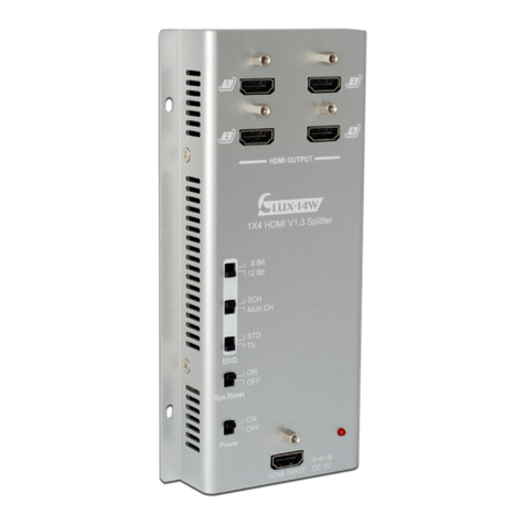
1 by 4 HDMI v1.3 Splitter
- ID# 758
Operation Manual
Introduction
This HDMI v1.3 Splitter is an impressive device that can handle all of your HDMI
signal distribution needs. From a single HDMI input it can transfer Deep olor (10-bit
and 12-bit) video and new lossless compressed (Dolby TrueHD, Dolby Digital Plus
and DTS-HD Master Audio) digital audio with high bandwidth up to 225MHz
(6.75Gbps) to four HDMI outputs. Besides splitting and distributing, it also amplifies
and equalizes your signal, providing high I/O performance on both audio and video.
On top of that, this device provides additional features like E , EDID and a system
reset function for maintaining superb image quality.
Application
 Simultaneous display of one source on 4 TVs
 Show room display control
 Educational demo
 Installation usage
System
Requirements
 Input source equipments with HDMI output connector(s)
 Output displays with HDMI input connector(s)
Features
 HDMI 1.3, HD P1.1 and DVI1.0 compliant Receiver
 Deep color video up to 12bit, 1080p@(24/60)Hz
 One HDMI source for simultaneous connection/display onto four HDMI
displays
 HD P keysets that allow each output to work independently when
connected to an HDMI display
 Splits a single HDMI source into four outputs(max.) without signal loss
 Supports DVI source and display via an HDMI to/from DVI adaptor
cable
 Supports LP M 7.1 H, Dolby TrueHD, Dolby Digital Plus and DTS-HD
Master Audio transmission (32-192kHz Fs sample rate)
 Supports a wide range of P and HDTV resolutions from VGA to UXGA
and 480i to 1080p
 HDMI cable distance testing showed that with 1080p/8bits resolution:
the Input/Output source can reach up to 20/15 meters away, and at
1080p/12bits the I/O source can reach up to 10/10 meters.
Note:
A. able tested with AT-6E /23AWG/Solid, using cables of another type may result
in a different operating distance.
B. able distance test included the following: PS3 120G and 37" Samsung
12-bit L D TV.
. Figures provided in this manual are for reference only, actual
figures may depend on the source and display used along with the type of cable.
 Supports EDID functionality and settings for Deep olor and color space.
When EDID is switched to TV mode, the system will automatically detect Deep olor
(8 bits or 12 bits) and color space (RGB or Y/ b/ r) settings from the source's EDID
and record it into the unit.
 Supports xvY and E bypass and also system reset functions
 Has E function's one touch play & Record, programmable timer, menu
language, deck & device menu control, OSD display, device OSD transfer, remote
control pass through, system audio control and system standby
 System standby will only be actived once the last TV is switched to standby
Operating Functions
and
Controls
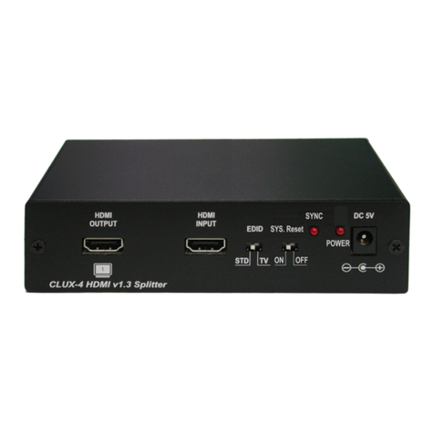
Front anel
①ower Switch: This switch turns the system on and off.
②ower LED Indicator: This LED is green when power is on and red when
the power is OFF.
③Sync LED: When an HDMI source is connected to the input port, this
LED will turn on only when the splitter has established a link.
④CEC button & LED: Press this button to switch the E function on or off. The
LED will turn yellow when the E is switched on. The factory default setting on.
Note:
1. In order to perform the E function, both source and display must have E
support.
2. The standby mode will only be activated when the last TV has been switched to
standby.
3. All four HDMI outputs support E functionality.
⑤Output LED: When the HDMI display has been connected to the output ports and
a signal is being sent the LED will switch on.
⑥EDID switch STD/TV: When switched to STD, EDID's manual settings of
deep color (12 or 8 bits) and color space (RGB or Y b r) are allowed. When
switched to TV, the splitter will use the external EDID. When EDID is switched to
STD users can change EDID's deep color between 8 or 12bits, under the condition
that all output support the same number of bits. For example, once the EDID is
switched to 12 bits but only 3 output displays support 12 bits and one supports 8 bits.
The 8 bits display will not be able to display any media. Users can also switch
between RGB or Y b r for the EDID's color space. But again, all output displays
need to comply with the selected settings. Most TV monitors support both RGB and
Y b r but some monitors only support RGB. When the EDID color space is set to
Y b r some monitors may not display any image and/or display a "reddish" image.
In cases like this switching the EDID to RGB is a must. Factory default is set as
Y b r.
When the EDID is switched to TV, the unit will detect the first HDMI output EDID
and record/save it in the unit. If the display attached to the first output source is DVI it
will skip to next output until the first HDMI is detected.
⑦Sys. Reset switch: It is suggested to always turn this setting OFF, unless
performing a system reset. By turning it to on, the system will reset
all TVs connected to the splitter to their HDMI input 1 once every 8~10 minutes.
Factory default is set as OFF.
Note:
The system reset switch only functions on displays with built-in E feature.
Rear anel
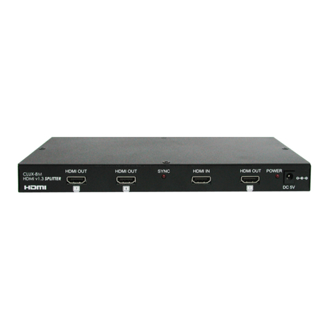
①HDMI Input: This slot is where you connect the output port of your HDMI /
DVI source (i.e., DVD, set-top box) using a HDMI / HDMI to DVI adaptor cable.
②HDMI output 1/2/3/4: These slots connect from the splitter to the input ports of
the HDMI displays. If there's more than one output connected, all
HDMI outputs will display an identical image.
③ower: This is the slot where you insert the 5V D power supply for
electrical power from an A outlet.
Connection and
Installation
Specifications
Frequency Bandwidth 2.25Gbps (single link)
Input ort 1x HDMI female port (Type A
connector)
Output orts 4x HDMI female ports (signal link)
HDMI Cable In 1080p 8-bit (20M), 12-bit (15M)
HDMI Cable Out 1080p 8-bit (10M), 12-bit (10M)
ESD rotection Human body model:
± 10kV (air-gap discharge)
± 6kV (contact discharge)
CB Stack – up 4-layer board impedance control
– differential 100Ω
– Single 50Ω
Input TMDS Signal 1.2 Volts (peak-to-peak)
Input DDC Signal 5 Volts (peak-to-peak, TTL)
HDMI Output Resolution 480i ~ 1080p, 1080p24, VGA ~ UXGA
ower Supply 5VD /2.6A (US/EU standards,
E/F /UL certified)
Dimensions (mm) 200(W) x 104(D) x 25(H)
Weight(g) 572
Chassis Material Metal
Silkscreen Color Black
Operating Temperature 0° ~ 40° / 32°F~ 104°F
Storage Temperature -20° ~60° / -4°F ~ 140°F
Relative Humidity 20% ~ 90% RH (non-condensing)
ower Consumption 5.5W (max)

Other manuals for CLUX-14CEC

2

Other Cypress Cables And Connectors manuals

Cypress CLUX-14S User manual

Cypress

Cypress CLUX-14S User manual

Cypress CLUX-14W User manual

Cypress

Cypress CLUX-14W User manual

Cypress CHDMI-210T User manual

Cypress

Cypress CHDMI-210T User manual

Cypress CLUX-8M User manual

Cypress

Cypress CLUX-8M User manual

Cypress CLUX-14CEC User manual

Cypress

Cypress CLUX-14CEC User manual

Cypress CH-12 User manual

Cypress

Cypress CH-12 User manual

Cypress CLUX-12E User manual

Cypress

Cypress CLUX-12E User manual

Cypress CLUX-8M3D User manual

Cypress

Cypress CLUX-8M3D User manual

Cypress CLUX-16E User manual

Cypress

Cypress CLUX-16E User manual

Cypress CPRO-8MCEC User manual

Cypress

Cypress CPRO-8MCEC User manual

Cypress CLUX-1H4CAT User manual

Cypress

Cypress CLUX-1H4CAT User manual

Cypress CLUX-1H4CAT Installation manual

Cypress

Cypress CLUX-1H4CAT Installation manual

Cypress CLUX-3D12S1A User manual

Cypress

Cypress CLUX-3D12S1A User manual

Cypress CDVI-8 Installation manual

Cypress

Cypress CDVI-8 Installation manual

Cypress CLUX-12S User manual

Cypress

Cypress CLUX-12S User manual

Cypress CLUX-14W User manual

Cypress

Cypress CLUX-14W User manual

Cypress CLUX-12S User manual

Cypress

Cypress CLUX-12S User manual

Cypress CLUX-4M User manual

Cypress

Cypress CLUX-4M User manual

Cypress CHDMI-210T User manual

Cypress

Cypress CHDMI-210T User manual

Popular Cables And Connectors manuals by other brands

National Instruments 9212 CALIBRATION PROCEDURE

National Instruments

National Instruments 9212 CALIBRATION PROCEDURE

EFB Elektronik GmbH 37667SW.1 installation instructions

EFB Elektronik GmbH

EFB Elektronik GmbH 37667SW.1 installation instructions

Techno TH381 Assembly instructions

Techno

Techno TH381 Assembly instructions

Crestron HZA-KEY1 quick start guide

Crestron

Crestron HZA-KEY1 quick start guide

Scame 899.AS5AR312 Assembly instructions

Scame

Scame 899.AS5AR312 Assembly instructions

FeherGuard FG-1B Assembly instructions

FeherGuard

FeherGuard FG-1B Assembly instructions

Philips SWA4415W Specifications

Philips

Philips SWA4415W Specifications

nvent RAYCHEM BTV Installation and maintenance manual

nvent

nvent RAYCHEM BTV Installation and maintenance manual

Staubli CombiTac Assembly instructions

Staubli

Staubli CombiTac Assembly instructions

SMART-AVI HDS8P-4K user manual

SMART-AVI

SMART-AVI HDS8P-4K user manual

BZB Gear BG-UHD-DA1x24 user manual

BZB Gear

BZB Gear BG-UHD-DA1x24 user manual

SC&T GL001HP user manual

SC&T

SC&T GL001HP user manual

Telegärtner MPPI30-HS Assembly instructions

Telegärtner

Telegärtner MPPI30-HS Assembly instructions

BD Q-Syte Instructions for use

BD

BD Q-Syte Instructions for use

IDEAL APP SBS Series Assembly instruction

IDEAL

IDEAL APP SBS Series Assembly instruction

MRO Electric HMI ZSUSBB Quick reference guide

MRO Electric

MRO Electric HMI ZSUSBB Quick reference guide

Kramer TBUS-100XL user manual

Kramer

Kramer TBUS-100XL user manual

Element ELE4023 user manual

Element

Element ELE4023 user manual

manuals.online logo
manuals.online logoBrands
  • About & Mission
  • Contact us
  • Privacy Policy
  • Terms and Conditions

Copyright 2025 Manuals.Online. All Rights Reserved.