Daavlin 7 Series User manual

OPERATING INSTRUCTIONS AND GENERAL INFORMATION
HOME PHOTOTHERAPY
MANU0027 Rev 12 1/17/11
7 Series
& 2 Series
UV Series
M Series
1 Series

1
TABLE OF CONTENTS
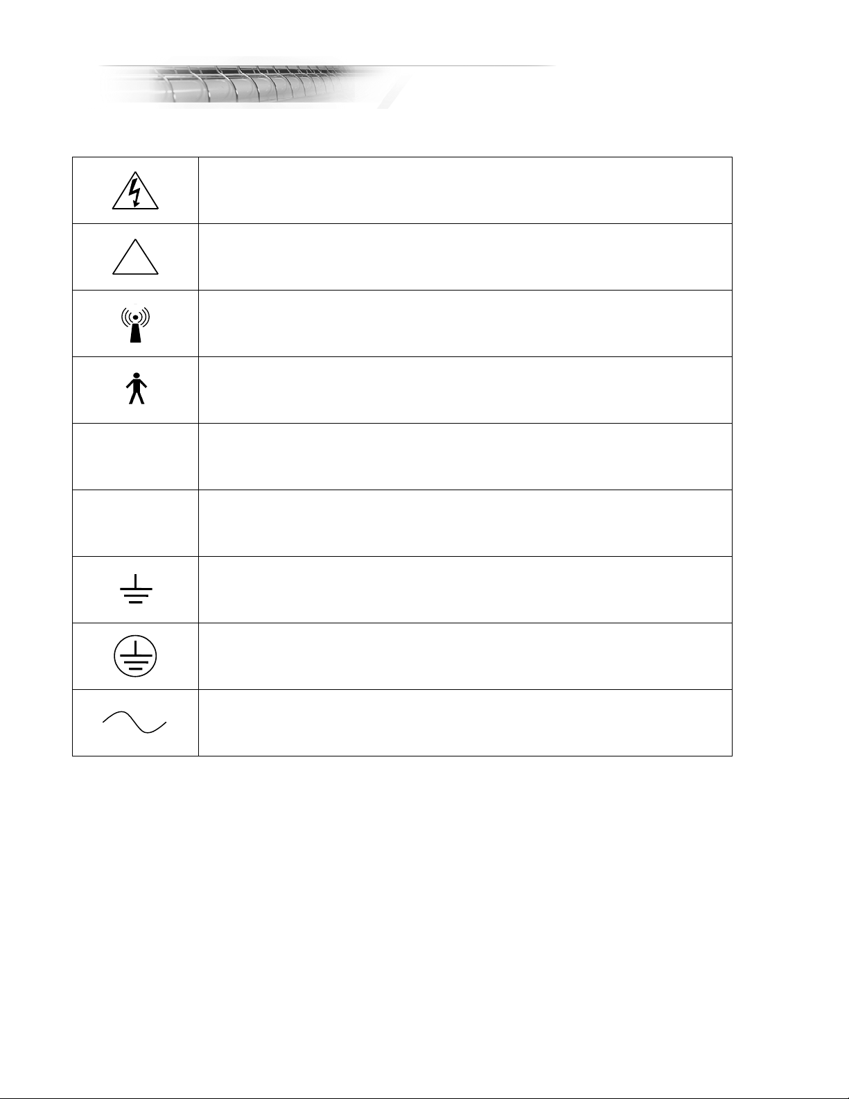
Symbols.........................................................................................................................3
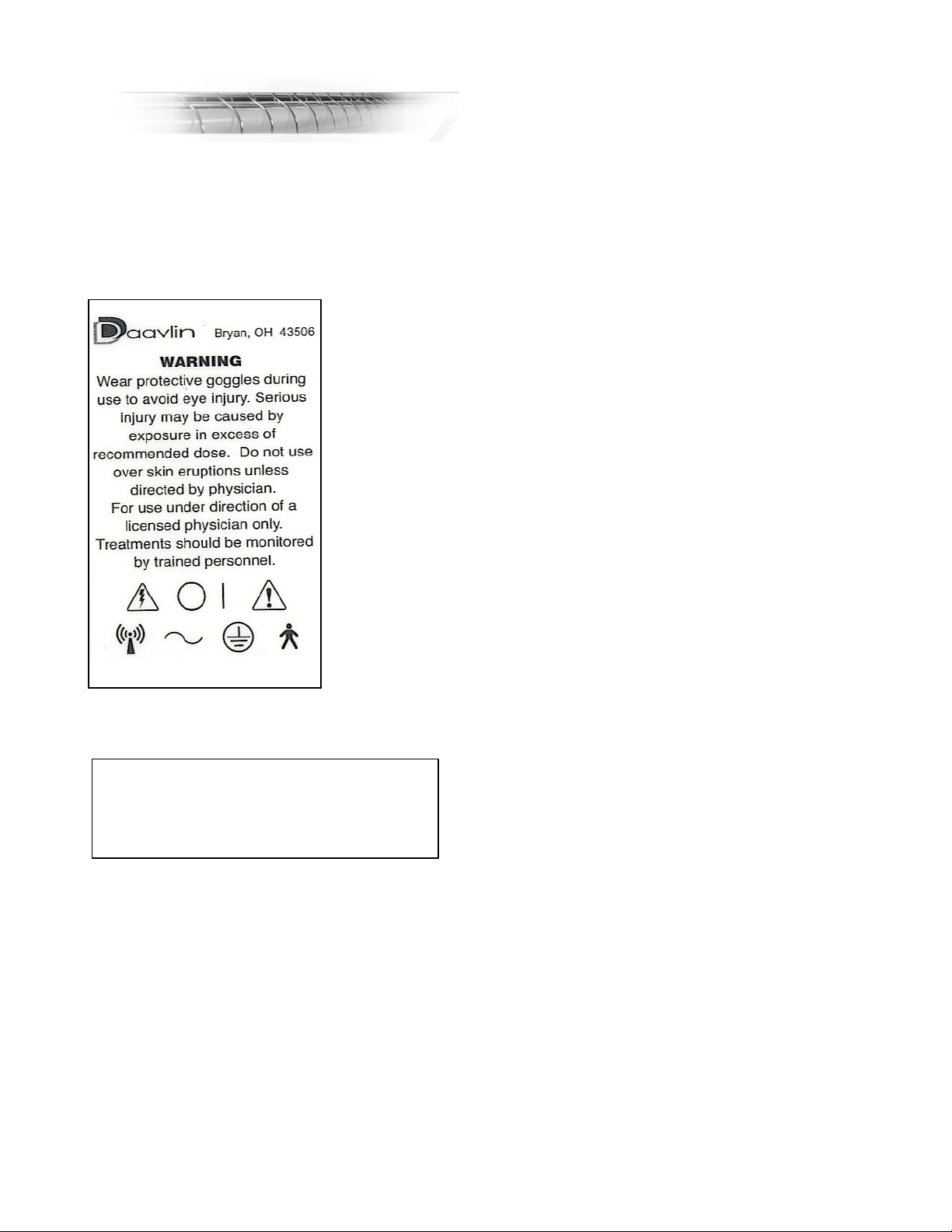
Warning Label ...............................................................................................................4
Identification Label.........................................................................................................4
General Overview ..........................................................................................................5
Inspect the Lamps in your Unit ..........................................................................6
Lamp Replacement Guide .................................................................................6
Select a Site.......................................................................................................6
General Precautions ..........................................................................................6
General Treatment Guidelines...........................................................................7
Device Specific Information ...........................................................................................8
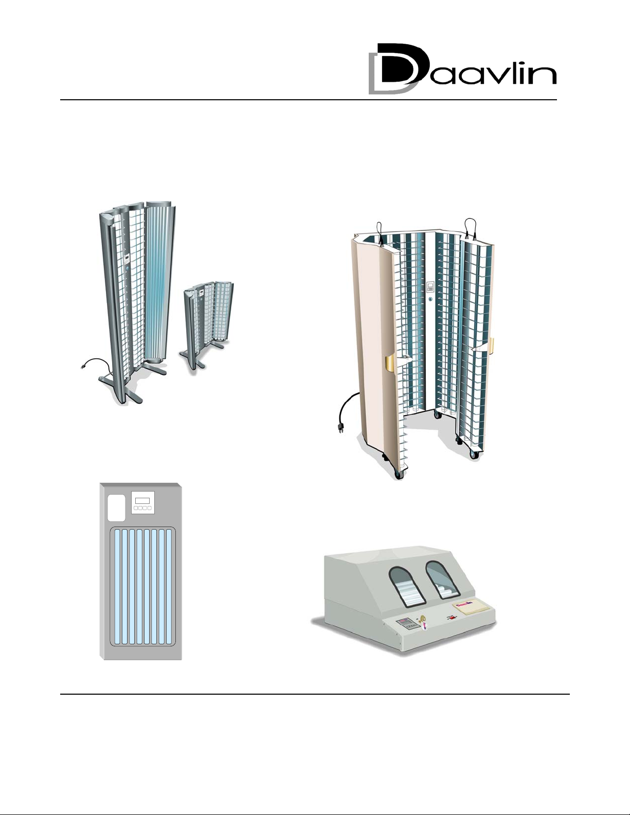
UV Series...........................................................................................................8
Available Lamps Types & Number of Lamps: ........................................8
UV Series Unpacking & Assembly .........................................................8
Circuit Breaker .......................................................................................8
UV Series Electrical Requirements ........................................................8
How to Position Yourself ........................................................................9
UV Series Lamp Removal and Replacement.........................................9
7 Series & 2 Series General Information ...........................................................10
Available Lamp Types & Number of Lamps:..........................................10
7 and 2 Series Unpacking & Assembly ..................................................10
7 and 2 Series Electrical Requirements .................................................12
How to Position Yourself ........................................................................12
7 Series & 2 Series Lamp Removal & Replacement..............................12
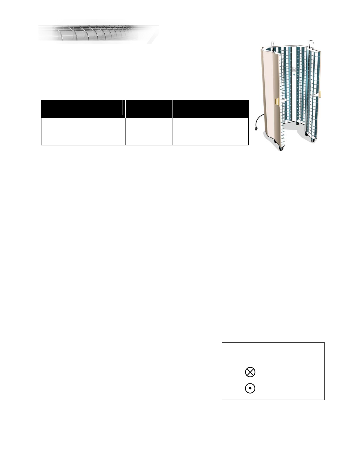
M Series General Information ............................................................................13
Available Lamp Types & Number of Lamps:..........................................13
M Series Unpacking & Assembly Guide ................................................13
Special Instructions for Combination Units ............................................13
M Series Electrical Outlet Requirements ...............................................14
How to Position Yourself ........................................................................14
M Series Lamp Removal and Installation...............................................14
1 Series General Information .............................................................................15
Available Lamp Types (All units equipped with 4 lamps) .......................15
Unpacking Guide....................................................................................15
1 Series Electrical Requirements ...........................................................15
How to Position Yourself ........................................................................15
Lamp Removal & Replacement Instructions ..........................................15
Operating the Flex Control System................................................................................16
Unlocking the Device .........................................................................................16
Setting or Changing the Key Code: ...................................................................16
Flex Dosimetry or Flex Time Control .................................................................16
Flex Dosimetry Instructions................................................................................16
The Backup Time ...................................................................................17
Power Output Measurement ..................................................................17
Setting up a Treatment...........................................................................18
Special Functions of the Flex Dosimeter................................................20
Special Notes .........................................................................................20
Flex Timer Instructions.......................................................................................20
Determining a treatment time.................................................................20
Entering a treatment time.......................................................................21
Special Functions of the Flex Timer.......................................................22
Special Notes .........................................................................................22
Care of your Phototherapy Unit .....................................................................................23

2
Recommended Maintenance Schedule .............................................................23
Cleaning.............................................................................................................23
Lamp Replacement............................................................................................23
Calibration..........................................................................................................24
Refilling a Light Prescription ..............................................................................24
Warranty ........................................................................................................................25
How Daavlin Handles Warranty and Service .....................................................26
Responsibilities of the Buyer..............................................................................26
Contact Information............................................................................................26

3
SYMBOLS
Following is a chart detailing all symbols located on your device and their meaning:
DANGEROUS VOLTAGE
!ATTENTION, CONSULT ACCOMPANYING DOCUMENTS
NON-IONIZING RADIATION
TYPE B EQUIPMENT
ION
|OFF
EARTH (ground)
PROTECTIVE EARTH (ground)
ALTERNATING CURRENT

4
WARNING LABEL
A warning label is affixed to your Daavlin phototherapy device in a prominent and easily readable
position. The label is of a size and shape similar to the example shown below. Please read the label
carefully as it contains important safety information for you.
In addition to the warning label, an identification label indicates the serial number and date of
manufacture that is specific to your device.
Identification Label
~ Volts: XXX Amps: XX Hertz: XX
Model: XSeries XXX
Serial Number: XXXXX-XXXXX-XXXX
Daavlin Company Bryan, Ohio USA

5
GENERAL OVERVIEW
This manual covers the following phototherapy equipment:
UV Series
7 Series
2 Series
M Series
1 Series
Your device may be equipped with a variety of different lamps and may be manufactured to a number
of different electrical specifications to meet national and international standards. It may also be
equipped with either a Flex™ integrating dosimetry control or a Flex timer control. And, in either case,
your physician may have prescribed your device with the FlexRx system that limits the total number of
exposures that the device will deliver. This manual is applicable for all lamp configurations, electrical
specifications and control types.
This section of the manual, the General Overview, covers topics such as site location, the initial
inspection of the device, lamp type confirmation, eye protection, precautions and phototherapy in
general. These topics are common to all devices.
Beginning on page eight (8) you will find Device Specific Information on the UV, 7, 2, M, and 1
Series devices.
The next section, beginning on page sixteen (16), Flex Operating Instructions provides operating
instructions for all devices.
Finally, the last section, Care of Your Unit, beginning on page twenty-three (23), contains information
concerning the maintenance, cleaning, re-lamping, and calibration (where applicable) of your device
along with warranty and service contact details.
We suggest that you first read the sections concerning site selection and general inspection under
Overview and then the instructions that are Specific to your device with regard to unpacking and
assembly.
When you first receive the device:
Inspect the box
Any signs of shipping damage should be noted on the shipping receipt that you will be asked to sign
by the delivering carrier. If damage is discovered after unpacking the unit, save all packing materials
and call Daavlin at 1-800-322-8546 for inspection and repair.
The delivering carrier must be notified of any shipping damage within twenty-four (24) hours
to protect your right to an insurance claim.
Locate the following materials
■Time chart ■Power Output Certificate ■Protective Eyewear ■Manual

6
Inspect the Lamps in your Unit
Your device can be equipped with a variety of different lamps, each having a different effect on the
skin. It is important to check that the proper kind of lamps are installed in the device. Consult the list
shown in the table below and if there is any question as to whether or not it is equipped with the
lamps that you have been prescribed, contact Daavlin immediately. The code numbers shown are
generally located at the base of the lamp.
Warning: A burn can result in as little as 15 seconds of exposure to UVB.
Warning: Blue Light can be hazardous to the eyes. Use Daavlin-approved eye-wear.
Lamp Replacement Guide
Select a Site
A site should be chosen within reach of the specified electrical outlet (see Electrical Outlet
Requirements within the section for your specific device) and where the unit can be left in place
without being in the way of traffic flow. It is important that the unit be properly grounded. Extension
cords are not recommended. The site should not be in any area where water or moisture might
collect and should be protected from access by children. Exposure to ultraviolet light over extended
periods of time may cause carpets, wall coverings and furnishings to fade.
General Precautions
WARNING: TO AVOID EYE INJURY DURING TREATMENT, YOU MUST WEAR THE TIGHTLY
FITTING ULTRAVIOLET BLOCKING GOGGLES PROVIDED WITH YOUR DEVICE. IF
PSORALENS (PUVA) ARE BEING USED, THE EYES SHOULD BE PROTECTED FROM
EXPOSURE TO ULTRAVIOLET (SUNLIGHT) FOR 24 HOURS AFTER TAKING THE DRUG.
ULTRAVIOLET BLOCKING GLASSES ARE PROVIDED WITH DEVICES EQUIPPED WITH UVA
LAMPS FOR THIS PURPOSE. BLUE LIGHT CAN ALSO BE DAMAGING TO THE EYES. WEAR
THE GRAY OR AMBER COLORED PROTECTIVE EYEWEAR PROVIDED.
All other persons should vacate the treatment area during a treatment session to avoid unnecessary
exposure to light energy.
WARNING: Consult your physician about protecting other areas of your body that may never have
been exposed to sunlight.
Typically
Used In
UVA
UVA1
Narrow
Band
UVB
Broad Band
UVB
Red Blue
(405)
UV & 7 Series F72T12BL/HO TL-01/100W FS72T12HO N/A N/A
M & 2 Series F24T12BL/HO TL-01/20W FS24T12HO N/A N/A
UVA = PLL-36W/091 Series
UVA1 = PLL-36W/10
PLL-36W/01 PLL-36W/-06 PLL-36W/15 PLL-36W/O

7
General Treatment Guidelines
Always check with your physician before you start your home treatments. Show him or her these
instructions. Your physician is the final authority for your treatment. Depending upon your particular
circumstances, he or she may modify these directions. Always follow your physician’s instructions.
You will need a notebook in which to record the date, time or dose in Joules or milliJoules (dosimetry
models only) and duration of each of your treatments along with any other notes regarding your
treatment or treatment results.
You will need to purchase lip balm and sunscreen with an SPF (Sun Protective Factor) of 30. Check
with your physician to determine whether or not you should use an alcohol or cream based
sunscreen.
For your first treatment, unless otherwise instructed by your physician, do not exceed a time of 15
seconds.
If you are red or uncomfortable after any treatment, do not resume the treatment until the redness has
subsided. If redness and discomfort are severe, you should discuss this with your physician.
Increases of less than 15 seconds may be necessary for some patients. Once initial pinkness has
been achieved, you should follow the treatment regimen prescribed by your physician.
After each treatment, record in your notebook the date and time of day of your treatment, the length of
each exposure, the dose, if you are using a Flex Dosimeter, and any other appropriate information
(e.g. forgot lip balm, put sunscreen on tender area, etc).
Never take more than one treatment in a single day and never more frequently than 12 hours apart.
For example, don’t take a treatment late at night followed by an early morning treatment.
If after a treatment, a small area feels sunburned, you may protect that area with sunscreen for the
next several treatments or until that area appears normal. (Make a note in your notebook.) You
should see your physician at the intervals he or she requests when you are actively using the unit.
Always take your notebook with you when you see your physician.

8
DEVICE SPECIFIC INFORMATION
UV Series
Available Lamps Types & Number of Lamps:
Numerals = Number of Lamps N/A = Not Available
UVA Narrow Band
UVB
Broad Band
UVB
UVA / Narrow
Band UVB
12 12 12 N/A
16 16 16 N/A
24 24 24 12 + 12
This section covers topics that are specific to the UV Series.
The Flex Dosimetry or Flex Timer operating instructions are covered on pages sixteen (16) through
twenty-two (22).
UV Series Unpacking & Assembly
The UV Series full-body device is shipped upright in a large cardboard container. Exercise caution as
the fluorescent lamps can be broken if the unit is not unpacked properly.
Using as many people as available but at least two, move the box into the area where the device will
be used. If there are no stairs, and since the unit is on castors, it may be easier to remove it from the
box at the earliest opportunity so that you can simply roll it into position. If there are stairs, you may
consider hiring a professional moving company to move the device into position.
To unpack the unit, first use metal cutters to cut the banding that encircles the package. Use extreme
caution as these bands are under tension and can snap outward when the tension is released. Next,
remove the front cardboard cover. Use a heavy-duty screwdriver to remove the staples. Again be
careful as the staples are sharp and can cause injury. When the front cardboard cover has been
removed, carefully pull the device forward on its castors until it is clear of the box. Take care not to
discard the accessory package which contains your protective eyewear.
Once in position, remove the shipping bars. A ¾” end wrench will be required to loosen and remove
the bolts that hold the shipping bars in place. There is no further assembly required other than to plug
the unit into the appropriate electrical outlet (See Electrical Outlet Requirements below). If your
device is equipped with an optional platform, place the platform inside the machine once it is located
in its final position.
Circuit Breaker
Each UV Series unit is equipped with a circuit breaker that is
located under the frame, at the back right hand side of the
machine. Its location is indicated by the circuit breaker label
(right). When setting up your unit, ensure that the breaker is in
the ON position.
UV Series Electrical Requirements
The number of lamps in a unit determines the voltage, amperage, wire size and outlet necessary to
safely support the unit’s operation. The table and diagrams below define these requirements for each
MAIN DISCONNECT
CIRCUIT BREAKER
l ==ON = RIGHT
O== OFF = LEFT
UV Series

9
lamp variation. UV Series that are shipped outside the USA and Canada (230 volt units) will require
local installation of a15-amp plug on the end of the cord that meets local electrical standards.
Model Amps Wire Gauge Diagram Required Outlet
24 lamp, 120 volt 30 amps 10 AWG A NEMA L5-30P
16 lamp, 120 volt 20 amps 12 AWG B NEMA L5-20P
12 lamp, 120 volt 15 amps 14 AWG C NEMA 5-15P
230 volt 15 amps 14 AWG locally specified
How to Position Yourself
Enter the unit and close the doors behind you. Center yourself within the unit. As nearly as possible, your
torso should not be closer to any one panel than to another. Standing closer to one of the sides may
cause localized streaking or burning.
UV Series Lamp Removal and Replacement
1) Consult the Lamp Replacement Guide for replacement lamp specifications.
2) Unplug the machine, then using a ¼” hex driver/socket, remove the screw from the bottom of
the grid that is in front of the lamp(s) to be removed.
3) Lift the grid out of the holes in the bottom lamp plate, pull the bottom of the grid toward you,
then lower the grid out of the holes in the top of the unit and set it aside.
4) Grasp the lamp to be removed with both hands and push up until it clears the bottom socket,
then remove the lamp. Reverse the process to install lamps and grid.
5) Reset the lamp hours age to zero. See instructions on page twenty-two (22).
C
B
A

10
7 Series & 2 Series General Information
Available Lamp Types & Number of Lamps:
Numerals = Number of lamps N/A = Not available
UVA Narrow
Band
UVB
Broad
Band
UVB
Doors
with
Lamps
Doors
without
Lamps
N/A 4 4 N/A Optional
6 6 6 N/A Optional
8 8 8 Standard N/A
10 10 10 Standard N/A
This section covers topics that are specific to 7 and 2 Series models. The only differences are the
number, type, and length of lamps and whether or not there are doors. If your device has a “D”
designation, it means that it is equipped with doors but without lamps in the doors. All models
available with Flex Dosimetry or Flex Timer control. The operating instructions are covered on pages
sixteen (16) through twenty-two (22)
7 and 2 Series Unpacking & Assembly
Since the packing box makes a useful work surface for assembly of your device, choose a place close
to where the unit will be installed to unpack it (however, if there are stairs or narrow hallways, it may
be easier to move the device after it has been assembled). In either case, be careful, as the
fluorescent lamps can be broken if the unit is not unpacked properly.
The grid that covers the lamps is not installed for shipping. When the box is unpacked, the grid will be
on top and should be set aside so that it can be installed after the unit is standing.
1. Use a heavy duty screwdriver to remove the staples. Be careful as the staples are sharp and can
cause injury. Remove the top of the box and set it aside. Next, break down the lower end of the
bottom box, exposing the base of the device.
2. Remove the following parts and accessories from the shipping container:
•Goggles (1 pair) and Glasses (UVA and visible light units only)
•Feet (2) – Figure 1
•Stabilizer bars (2) – Figure 2 (7 Series units with doors only – does not apply to 2 Series)
•Grid
2 Series
7 Series

11
Figure 1 Figure 2
3. Using two people, if available, twist the device 90oand rest it in the box on its side using the foam
at the top and center for support. Carefully remove the foam at the bottom of the device so that
you can install the feet. The second person should stabilize the device during installation of the
feet.
4. The four, 3 inch (7.5cm) screws used to attach the feet are pre-inserted in the bottom of the unit
but are not fully screwed in so that they can be easily identified. Use a large Philips head
screwdriver to remove them and then attach the lower foot first. Its “longer” side should be
towards the front of the device and the slide pads should be on the bottom. The foot should splay
outward from the device. Mount the foot using the screws that you removed from the bottom of
the device. Repeat the process for the top foot.
5. With the device still lying on its side, stand the device upright. With one person lifting at the top
and a second person at the foot to “catch” the unit, gently lift and tip the device forward until both
feet are on the ground.
6. Remove the remaining packaging foam and the cellophane wrap.
7. Mount the two stabilizer brackets (7 Series only). The screws for mounting the brackets are pre-
inserted into the unit about 14” (35cm) from the bottom of the unit and in each foot. Using a small
Philips Head screwdriver, remove the screws then position the brackets and replace the screws.
8. Gently slide the unit into its permanent position.
9. Install the power cord by inserting the female “D” shaped receptacle into the “D” shaped male plug at
the back of the device. Then, plug the unit into any grounded, three prong electrical receptacle.
10.Install the lamp grid after the unit has been properly assembled as described above. Hold the grid
so that it is oriented toward the lamps as shown below, with the grounding bracket toward the
floor.
Lamp Lamp
(726-xx only) Lamp
Bracket

12
11. Insert the perpendicular grid wires into the two holes in the top lamp plate and push the grid all the
way up. Swing the bottom of the grid in toward the lamps and insert the grid wires into the two holes
in the bottom lamp plate. Then, lower the grid until the bracket touches the bottom lamp plate. Using
a ¼” hex driver/socket, screw the bracket to the bottom lamp plate using one of the hex head, self-
tapping screws that are provided.
7 and 2 Series Electrical Requirements
Both the 7 and 2 Series devices are shipped within the USA and Canada with a standard three prong
grounded wall plug. Units designed for other voltages may be shipped with no wall plug, which would
then have to be locally obtained and installed. All 7 and 2 Series devices can be plugged into a
standard, grounded wall outlet.
Both 7 and 2 Series devices are equipped with onboard fuses. The fuse holders are located just
below where the power cord plugs into the unit. Should an onboard fuse blow, call Daavlin service to
determine an appropriate replacement.
How to Position Yourself
The recommended distance from the lamps for treatment is 9 inches (22cm). Mark that distance on
the floor in some manner. A similar system should be devised if you are using a 2 Series on a
tabletop or other non-floor surface area.
Your torso should not be closer to the lamps than this line. Standing closer to the lamps will cause
localized streaking or burning. Greater distances will increase the time necessary to receive a
therapeutic dose.
7 Series & 2 Series Lamp Removal & Replacement
1. Consult the Lamp Replacement Guide for replacement lamp specifications.
2. Unplug the machine. Then, using a ¼” hex driver/socket, remove the screw from the bottom
of the grid that is in front of the lamp(s) to be removed.
3. Lift the grid out of the holes in the bottom lamp plate, pull the bottom of the grid forward, then
slide it out of the holes in the top of the unit and set it aside.
4. Grasp the lamp to be removed with both hands and press down until it clears the top socket,
then remove the lamp. Reverse the process to install lamps and grid.
5. Reset the lamp hours age to zero. See instructions on page twenty-two (22).

13
M Series General Information
Available Lamp Types & Number of Lamps:
UVA Narrow
Band
UVB
Broad
Band
UVB
UVA/
Narrow
Band UVB
UVA/
Broad
Band UVB
10 10 10 6 UVA + 4
UVB
6 UVA + 4
UVB
M Series Unpacking & Assembly Guide
Assembly Instructions
1. With two people, lift the base from its box (the larger of two boxes) and place it where it is to be
used. Be sure to remove all of the accessories, such as the manual, power cord and eyewear
before discarding the box.
2. Remove the hood from its box (smaller box) and place it on the base with the arched openings
facing front. There is a flange on the bottom of the hood that fits over the upper edge of the fixture.
The hood is designed to fit tightly, so it may take some pressure to seat it properly.
3. Electrically connect the hood by plugging the electrical cord extending from the back of the hood into
the designated receptacle on the back of the base.
4. Install the power cord by inserting the female “D” shaped receptacle into the corresponding male plug
at the back of the device. Then, plug the unit into any grounded service of the appropriate voltage.
Note: 120-volt, 60 hertz units are shipped with a grounded, three-conductor wall plug. Units
designed for other voltages may be shipped with no wall plug, which would then have to be locally
obtained and installed.
Hood Lamps
The hood lamps have an “ON/OFF” switch so that they can be turned off if desired. When this switch is in
the ON position, the hood lamps will light when the base lamps turn on.
On combination M Series models that have both UVA and UVB lamps, the hood is equipped with UVA
lamps only. The UVA lamps will not operate when UVB is selected.
Special Instructions for Combination Units
With Flex Dosimetry: If your unit has both UVA and UVB lamps and Integrating Dosimetry, there is
a separate controller for UVA and UVB. Be sure to enter the desired UVA dose into the controller
labeled UVA or the desired UVB dose into the controller labeled UVB.
With Flex Timer: There is a switch in the center of your control panel that sets the device to either
UVA or UVB operation. Push the switch up for UVA and down for UVB.
All Combination Units: The UVA lamps will be the first four lamps in the unit. The UVB lamps will
be the last four. Therefore, if you are using the UVA lamps, position your hands or feet at the front of
the device. If using the UVB lamps, place your hands or feet in the back half of the unit.
M Series

14
M Series Electrical Outlet Requirements
All models require a grounded, three prong electrical outlet rated for at least 15 amps. Each machine
is equipped with a power inlet which incorporates two 5x20mm fuses. M Series devices can be built
to meet any international electrical standard.
How to Position Yourself
The hands, feet or elbows should be placed through the arched exposure ports in the front shield and laid
directly on the plastic guard that covers the lamps. Intensity is highest towards the horizontal center of the
unit. Rings or other jewelry may cause scratching of the shield and should therefore be removed.
M Series Lamp Removal and Installation
1. Consult the Lamp Replacement Guide on page six (6) for replacement lamp specifications.
2. Unplug the machine and disconnect the power cord for the hood before removing the hood.
3. Remove the hood from the base. The hood lamps are then easily accessible on 120-volt units
if those are to be replaced.
4. To remove the lamps in the base, use a flat head screw driver to remove the screw at the back
of the unit that holds the acrylic shield in place.
5. Then slide the acrylic forward to remove it from the base.
6. Grasp the lamp to be removed with both hands and push it to the left until it clears the right
socket. Then remove the lamp. Reverse the process to re-assemble the unit.
7. Reset the lamp age hours to zero - see instructions on page twenty-two (22).
Note: UVA lamps are always closest to the front in combination machines. In combination devices
the hood lamps are always UVA. Be sure to get the correct lamp type in the correct socket when
replacing lamps.

15
1 Series General Information
Available Lamp Types (All units equipped with 4 lamps)
yNarrow Band UVB yBroad Band UVB yUVA yUVA1
yBlue Light yRed Light yIntense White Light (SAD)
Unpacking Guide
Open the box at the top and using two hands at each side of the device, pull the 1 Series out of the
box, including the foam packers at each end. Remove the foam.
Be sure that you locate the power cord, manual and eyewear before discarding the shipping box.
Plug the “D” shape female fixture into the corresponding receptacle on the lower left side of the
device. Plug the unit into an appropriate wall outlet. It is now ready for use.
1 Series Electrical Requirements
The 1 Series can be plugged into any grounded, three prong, household electrical outlet.
Note: 120-volt, 60 hertz units are shipped with a grounded, three-conductor wall plug. Units
designed for other voltages may be shipped with no wall plug, which would then have to be locally
obtained and installed.
How to Position Yourself
Hand Treatment: Place the device flat on a table and place your hands directly on the plastic lamp
guard. They should be as close as possible to the center of the fixture for best results.
Larger Area Treatment: Stand the device so that the lamps are perpendicular to the surface on which
the device is standing. Position the part of your body you will be treating eight (8) inches (21cm) away
from the lamps.
Lamp Removal & Replacement Instructions
1. Consult the Lamp Replacement Guide for replacement lamp specifications.
2. Unplug the machine. Then, using a 5/64” Allen wrench, remove the two screws on each side of
the device.
3. Lift off the top of the device (like removing the top from a gift box). The lamps will be exposed.
4. At the end of each lamp is a clear plastic clasp that holds the lamp in position. Press both thumbs
on the outside of the device and use your index fingers to reach to the side of the lamps and pull
the sides of the clasp outward until it releases and the clasp can be removed.
5. Push the red button on top of the lamp socket. The base of the lamp will release. With one hand
near the base and the other near the clasp at the opposite end, grasp the lamp to be removed and
pull both ends upward at the same time until it clears both the clasp and the lampholder/socket.
6. To replace the lamp, reverse the process.
7. Reset the lamp hours following the instructions shown on page twenty-two (22).
1 Series

16
OPERATING THE FLEX CONTROL SYSTEM
Unlocking the Device
To prevent unauthorized use, the device will “self lock” when it has not been used for twenty (20)
minutes. To unlock, press any key. The word “CODE” will appear. Press ▲until the numeral 7
appears, then press ENTER. This is the factory default key code. If you wish to personalize or
change your keycode, see the next section.
Setting or Changing the Key Code:
Press MODE, ◄and ENTER at the same time Then…
Press ▲until the display reads 9 Then…
Press ENTER Then…
Press MODE and ▲at the same time Then…
Enter desired Key Code (Set to 0000 to disable) Then…
Press ENTER
Flex Dosimetry or Flex Time Control
Daavlin phototherapy equipment is available with two types of control system; Flex Dosimetry and
Flex Timer. Verify the type of control system you have and proceed to the applicable operating
instructions.
Note: If your serial number contains ( ****-** X -****) then the unit has a dosimetry controller.
If your serial number contains ( ****-** T-****) then the unit has a timer only controller.
Flex Dosimetry Instructions
Daavlin integrating dosimetry systems have a built-in power
meter that measures energy output. This information is used to
determine the exact amount of time that each treatment will last.
Unlike timer based systems, the dose is entered in milliJoules
(UVB) or Joules (UVA) (Blue Light).
The output of fluorescent lamps varies with age, use and other
factors such as room temperature. Measuring for these
variations and then integrating them into the dose time is an
effective way to ensure the precision of each treatment.

17
The Backup Time
An important safety feature of Daavlin’s dosimetry system is the use of a backup safety time. While
the dose is entered in Joules or milliJoules, a backup time must also be entered as a safety check.
The treatment will stop when the dose has been delivered, OR, when the backup time has elapsed,
whichever comes first. At the end of the treatment, the dose delivered and the time elapsed are
alternately displayed so that you will know which limit ended the treatment.
When preparing for a treatment, the back-up time is entered first. To determine an appropriate back-
up time, it is necessary to know the power output of the device. Those instructions follow:
If you have a 1 Series and will be treating your hands, elbows or other areas of the body that can
be placed directly on the plastic guard of the device, use the instructions directly following. If
you will be treating larger areas of your body where it is impossible to have the skin in direct
contact with the plastic lamp guard, then, be sure to read the additional instructions on pages 19
and 20.
Power Output Measurement
Power output values of the device as measured at the factory are shown on the Power Output
Certificate included in your manual. Note: It is not necessary to take a power output reading before
each treatment. We suggest once every couple of weeks or earlier if the backup time ends your
treatment before the full dose has been delivered.
Press Comments…
MODE When just a decimal point is displayed, the machine is “asleep “(energy
saving feature) Press MODE or any key to “wake up” the device.
▲Press this button five times until the “5” digit appears, then…
◄Press this button twice so that 05:00 shows in the display, then…
ENTER Press once to lock in the time. Then…
MODE This puts you in the dose entry mode. Then …
▲Press this button five times until “0005” appears, then…
◄Press ◄until 5000 is displayed if checking a UVB device or 50.0 is
displayed if checking a UVA or visible light (blue, red) device.
ENTER Press twice. The lights will come on. When measuring ultraviolet be sure
to apply SPF 30 sunscreen to exposed areas of the skin and wear goggles
while monitoring the device.
MODE The time countdown will be in progress. Allow the machine to run until 30
seconds remains. Stand to the side of the device. Then…
POWER The system will display the power output of the lamps at the clear plastic
lamp guard. A value such as P9.0 (example) will display. Write down the
value. When the machine shuts off, press…
END

18
Once you know the power output, nine (9) milliwatts in the example above, consult the laminated
Backup Time Chart, a partial example of which is included below. The numbers in the top row of the
chart (horizontal axis) represent a range of power output values. Find the value that is closest to the
power output of your device.
The numbers in the column at the left (vertical axis) represent a range of treatment doses. Find your
dose then trace that row to the right until it intersects with the column corresponding to the current
power output of your device. The backup time is shown where the two lines intersect. The times are
rounded up to the nearest 10-second increment. On the partial time chart shown below, thirty (30)
seconds is the backup time at a power output of 9.0 mw and a dose of 280 mJ.
PARTIAL UVB TIME CHART
mw/ cm2 Power output
The UVA and Blue Light Backup Time Charts (not shown) are configured the same as the UVB
Backup Time Chart. The doses are listed in Joules and the energy output levels and times are
different than the UVB output levels. Each chart is clearly marked.
Determining a 1 Series Backup Time when the device is positioned away from your body:
Since the 1 Series can be used in two ways, there are two power output values of importance. If you
are placing your hands, elbows or forearm (for example) directly on the plastic lamp guard, the energy
output there is higher. When you take a power output reading, this is the value that is shown on the
display. All of the above instructions apply.
However, if you are treating other, larger areas of the body where it is impractical to have your skin in
direct contact with the plastic guard, then place the device at a distance of eight (8) inches (20cm)
from the area to be treated. The power output there will be 1/3 the value at the plastic guard.
Therefore, if the measured output is 9 milliwatts, you would divide the power output by three. In the
above example, the “at a distance” power output would be 3 and your backup time would be one
minute and thirty seconds instead of thirty seconds.
Setting up a Treatment
(See additional instructions below for the 1 Series)
You will first enter a back up time (steps 1 – 4). Assume the back-up time to be 00:30
1. Press any key so that 00:00 is displayed.
2. Press ▲until the first digit of the backup time is displayed (“3” in this case).
3. Press ◄to move the “3” one space to the left.
4. Press ENTER to complete the backup procedure.
i. Now enter the actual dose. Assume 280 milliJoules. Therefore, the first digit is
a “2”. )
5. Press MODE to switch to dose mode.
MJ/cm2 2.8 3.0 3.6 4.0 4.5 5.0 6.0 7.0 9.0
240 01:50 01:20 01:30 01:20 01:20 01:10 01:00 01:00 00:30
280 02:00 01:30 01:40 01:30 01:30 01:20 01:10 01:00 00:30
320 02:20 01:50 01:50 01:40 01:30 01:30 01:20 01:10 00:40
Æ
È

19
6. Press ▲until the number “2” is displayed.
7. Press ◄to move the “2” one space to the left.
8. Press ▲until the number “8” is displayed.
9. Press ◄to move the “8” one space to the left and repeat until all desired digits are shown on
the display. In this example the last digit is a zero, so once you have moved the “8” into
position, the “0” already shows and you can move on to step 10.
10. When the desired dose is displayed, press ENTER.
Put on your goggles and position yourself per the instructions of your specific device.
11. Begin the treatment by again pressing ENTER.
To repeat the same dose for another exposure, press the END key to clear the display, and then
press the MODE and POWER keys at the same time and release. This displays and enters the
previous dose. Press ENTER to start the timer again.
Note: The system beeps three times to signal the end of the treatment and then flashes the
delivered dose on the display alternating with the elapsed time. If the complete dose is not
delivered, meaning that the backup time was reached before the dose was fully delivered, this is
an indication that the backup times being entered are not long enough. Verify that the sensor is
clean, unobstructed and centered in the hole in the reflector. Then, re-take your power output
reading and adjust the back-up time. It is normal to have to increase back-up times due to aging
lamps and/or because of slow starting lamps, low room temperatures or low line voltage.
Special 1 Series Instructions when the device is positioned away from your body:
When setting up a treatment where it is impractical for the area being treated to be in direct contact
with the plastic guard, you should position the device 8 inches (20cm) from the body. Since the power
output there is 1/3 lower than at the plastic lamp guard, it is necessary to multiply the prescribed dose
by three. Therefore, if your dose was 280 milliJoules, you would have to enter a value of 840
milliJoules along with a backup time for 840 milliJoules.
Other manuals for 7 Series
2
This manual suits for next models
4
Table of contents
Other Daavlin Medical Equipment manuals
Popular Medical Equipment manuals by other brands

Impulse Dynamics
Impulse Dynamics OPTIMIZER Integra CCM-D Patient manual

Auxilab
Auxilab MiniFuge-GD06 Operation and maintenance manual

Darco
Darco Web Ankle Brace quick guide

Smiths Medical
Smiths Medical Surgivet Advisor Quick reference guide

Synthes
Synthes Air Power Line II Instructions for use

Amico
Amico S-AM1-300X Operation & maintenance manual