dacell DN-300 User manual

DIGITAL INDICATOR
USER’S MANUAL
DN-300 (VER 1.0)
DACELL CO.,LTD.
Address : 37-9 Cheoksan 5gil ,Nami - Myeon , Seowon-Gu, Cheongju-
city ,
Chung-Buk,Korea
TEL :82-43-260-2242
FAX : 82-43-260-2245
http://www.dacell.com
E-Mail : info@dacell.com

1
CONTENTS
1. Features ⋅⋅⋅⋅⋅⋅⋅⋅⋅⋅⋅⋅⋅⋅⋅⋅⋅⋅⋅⋅⋅⋅⋅⋅⋅⋅⋅⋅⋅⋅⋅⋅⋅⋅⋅⋅⋅⋅⋅⋅⋅⋅⋅⋅⋅⋅⋅⋅⋅⋅⋅⋅⋅⋅⋅⋅⋅⋅⋅⋅⋅⋅⋅⋅⋅⋅⋅⋅⋅⋅⋅⋅⋅⋅⋅⋅⋅⋅⋅⋅⋅⋅⋅⋅⋅⋅⋅⋅⋅⋅⋅⋅⋅⋅⋅⋅⋅⋅⋅⋅⋅⋅⋅⋅⋅⋅⋅⋅⋅⋅⋅⋅⋅⋅⋅⋅⋅ 2
1-1. Calibration Method ⋅⋅⋅⋅⋅⋅⋅⋅⋅⋅⋅⋅⋅⋅⋅⋅⋅⋅⋅⋅⋅⋅⋅⋅⋅⋅⋅⋅⋅⋅⋅⋅⋅⋅⋅⋅⋅⋅⋅⋅⋅⋅⋅⋅⋅⋅⋅⋅⋅⋅⋅⋅⋅⋅⋅⋅⋅⋅⋅⋅⋅⋅⋅⋅⋅⋅⋅⋅⋅⋅⋅⋅⋅⋅⋅⋅⋅⋅⋅⋅⋅⋅⋅⋅ 2
1-2. Comparison Output⋅⋅⋅⋅⋅⋅⋅⋅⋅⋅⋅⋅⋅⋅⋅⋅⋅⋅⋅⋅⋅⋅⋅⋅⋅⋅⋅⋅⋅⋅⋅⋅⋅⋅⋅⋅⋅⋅⋅⋅⋅⋅⋅⋅⋅⋅⋅⋅⋅⋅⋅⋅⋅⋅⋅⋅⋅⋅⋅⋅⋅⋅⋅⋅⋅⋅⋅⋅⋅⋅⋅⋅⋅⋅⋅⋅⋅⋅⋅⋅⋅⋅⋅⋅⋅⋅ 2
1-3. Data Back-up ⋅⋅⋅⋅⋅⋅⋅⋅⋅⋅⋅⋅⋅⋅⋅⋅⋅⋅⋅⋅⋅⋅⋅⋅⋅⋅⋅⋅⋅⋅⋅⋅⋅⋅⋅⋅⋅⋅⋅⋅⋅⋅⋅⋅⋅⋅⋅⋅⋅⋅⋅⋅⋅⋅⋅⋅⋅⋅⋅⋅⋅⋅⋅⋅⋅⋅⋅⋅⋅⋅⋅⋅⋅⋅⋅⋅⋅⋅⋅⋅⋅⋅⋅⋅⋅⋅⋅⋅⋅⋅⋅ 2
1-4. Watch dog ⋅⋅⋅⋅⋅⋅⋅⋅⋅⋅⋅⋅⋅⋅⋅⋅⋅⋅⋅⋅⋅⋅⋅⋅⋅⋅⋅⋅⋅⋅⋅⋅⋅⋅⋅⋅⋅⋅⋅⋅⋅⋅⋅⋅⋅⋅⋅⋅⋅⋅⋅⋅⋅⋅⋅⋅⋅⋅⋅⋅⋅⋅⋅⋅⋅⋅⋅⋅⋅⋅⋅⋅⋅⋅⋅⋅⋅⋅⋅⋅⋅⋅⋅⋅⋅⋅⋅⋅⋅⋅⋅⋅⋅⋅⋅⋅⋅⋅⋅⋅⋅⋅⋅ 2
2. Precautions ⋅⋅⋅⋅⋅⋅⋅⋅⋅⋅⋅⋅⋅⋅⋅⋅⋅⋅⋅⋅⋅⋅⋅⋅⋅⋅⋅⋅⋅⋅⋅⋅⋅⋅⋅⋅⋅⋅⋅⋅⋅⋅⋅⋅⋅⋅⋅⋅⋅⋅⋅⋅⋅⋅⋅⋅⋅⋅⋅⋅⋅⋅⋅⋅⋅⋅⋅⋅⋅⋅⋅⋅⋅⋅⋅⋅⋅⋅⋅⋅⋅⋅⋅⋅⋅⋅⋅⋅⋅⋅⋅⋅⋅⋅⋅⋅⋅⋅⋅⋅⋅⋅⋅⋅⋅⋅⋅⋅⋅⋅ 3
2-1. Precautions for Installation⋅⋅⋅⋅⋅⋅⋅⋅⋅⋅⋅⋅⋅⋅⋅⋅⋅⋅⋅⋅⋅⋅⋅⋅⋅⋅⋅⋅⋅⋅⋅⋅⋅⋅⋅⋅⋅⋅⋅⋅⋅⋅⋅⋅⋅⋅⋅⋅⋅⋅⋅⋅⋅⋅⋅⋅⋅⋅⋅⋅⋅⋅⋅⋅⋅⋅⋅⋅⋅⋅⋅⋅⋅⋅⋅⋅⋅⋅⋅⋅⋅⋅⋅⋅⋅⋅⋅⋅⋅ 3
2-2. Precautions for Use ⋅⋅⋅⋅⋅⋅⋅⋅⋅⋅⋅⋅⋅⋅⋅⋅⋅⋅⋅⋅⋅⋅⋅⋅⋅⋅⋅⋅⋅⋅⋅⋅⋅⋅⋅⋅⋅⋅⋅⋅⋅⋅⋅⋅⋅⋅⋅⋅⋅⋅⋅⋅⋅⋅⋅⋅⋅⋅⋅⋅⋅⋅⋅⋅⋅⋅⋅⋅⋅⋅⋅⋅⋅⋅⋅⋅⋅⋅⋅⋅⋅⋅⋅⋅⋅⋅⋅⋅⋅ 3
3. Specification ⋅⋅⋅⋅⋅⋅⋅⋅⋅⋅⋅⋅⋅⋅⋅⋅⋅⋅⋅⋅⋅⋅⋅⋅⋅⋅⋅⋅⋅⋅⋅⋅⋅⋅⋅⋅⋅⋅⋅⋅⋅⋅⋅⋅⋅⋅⋅⋅⋅⋅⋅⋅⋅⋅⋅⋅⋅⋅⋅⋅⋅⋅⋅⋅⋅⋅⋅⋅⋅⋅⋅⋅⋅⋅⋅⋅⋅⋅⋅⋅⋅⋅⋅⋅⋅⋅⋅⋅⋅⋅⋅⋅⋅⋅⋅⋅⋅⋅⋅⋅⋅⋅⋅⋅⋅⋅⋅⋅⋅⋅⋅ 4
4. Front Panel ⋅⋅⋅⋅⋅⋅⋅⋅⋅⋅⋅⋅⋅⋅⋅⋅⋅⋅⋅⋅⋅⋅⋅⋅⋅⋅⋅⋅⋅⋅⋅⋅⋅⋅⋅⋅⋅⋅⋅⋅⋅⋅⋅⋅⋅⋅⋅⋅⋅⋅⋅⋅⋅⋅⋅⋅⋅⋅⋅⋅⋅⋅⋅⋅⋅⋅⋅⋅⋅⋅⋅⋅⋅⋅⋅⋅⋅⋅⋅⋅⋅⋅⋅⋅⋅⋅⋅⋅⋅⋅⋅⋅⋅⋅⋅⋅⋅⋅⋅⋅⋅⋅⋅⋅⋅⋅⋅ 5
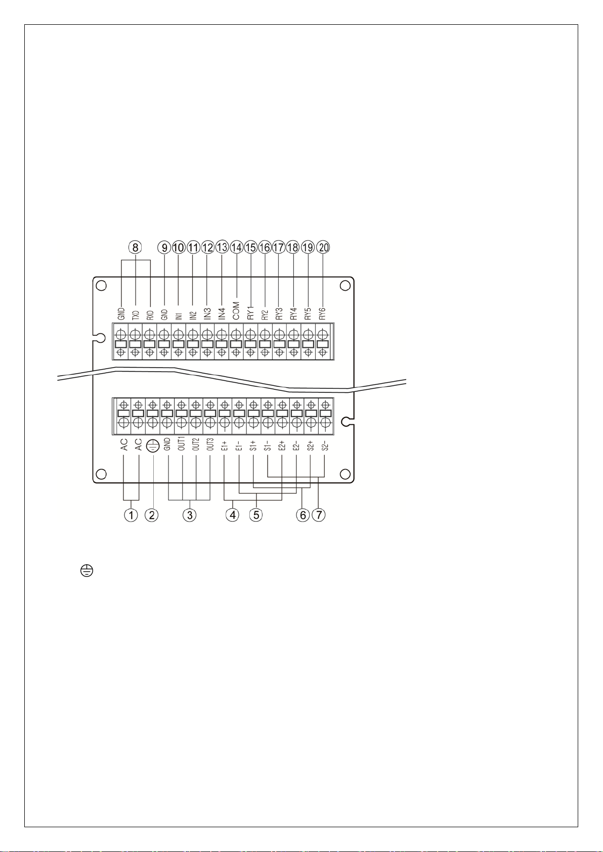
5. Rear Panel ⋅⋅⋅⋅⋅⋅⋅⋅⋅⋅⋅⋅⋅⋅⋅⋅⋅⋅⋅⋅⋅⋅⋅⋅⋅⋅⋅⋅⋅⋅⋅⋅⋅⋅⋅⋅⋅⋅⋅⋅⋅⋅⋅⋅⋅⋅⋅⋅⋅⋅⋅⋅⋅⋅⋅⋅⋅⋅⋅⋅⋅⋅⋅⋅⋅⋅⋅⋅⋅⋅⋅⋅⋅⋅⋅⋅⋅⋅⋅⋅⋅⋅⋅⋅⋅⋅⋅⋅⋅⋅⋅⋅⋅⋅⋅⋅⋅⋅⋅⋅⋅⋅⋅⋅⋅⋅⋅⋅⋅⋅⋅⋅ 6
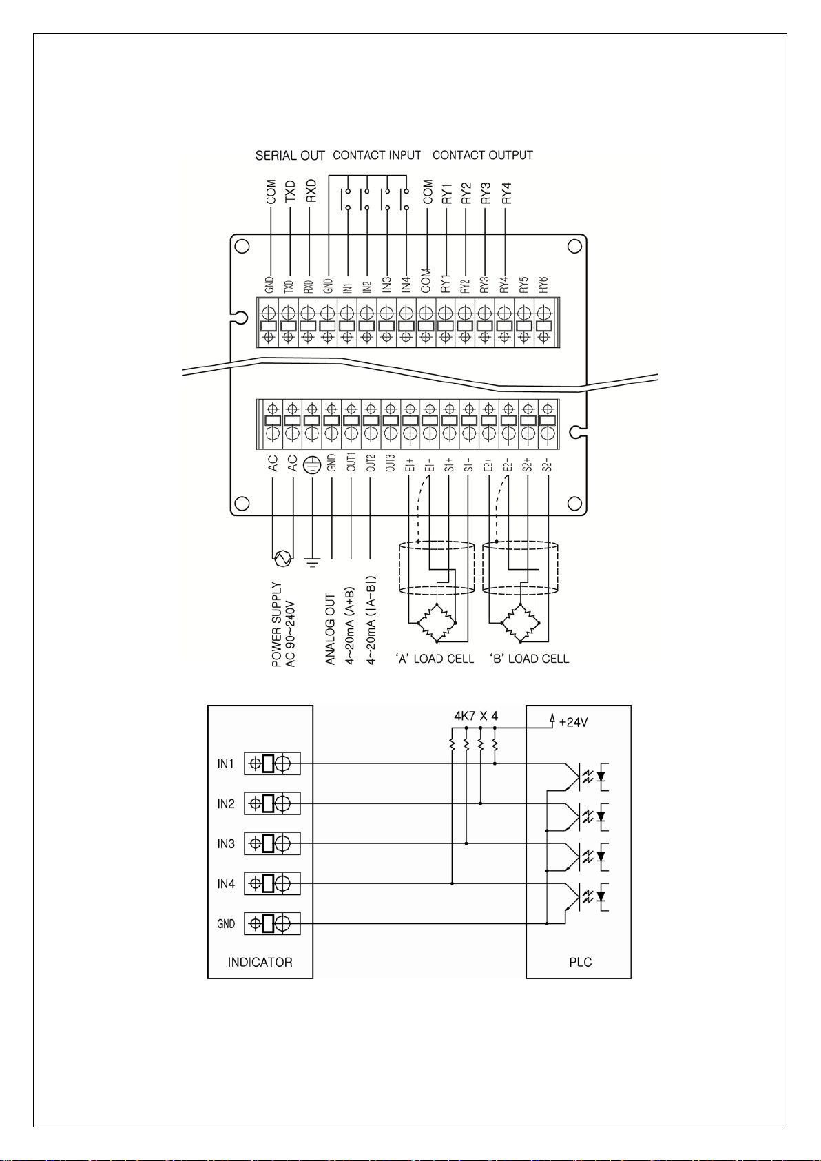
6. Wiring Diagram ⋅⋅⋅⋅⋅⋅⋅⋅⋅⋅⋅⋅⋅⋅⋅⋅⋅⋅⋅⋅⋅⋅⋅⋅⋅⋅⋅⋅⋅⋅⋅⋅⋅⋅⋅⋅⋅⋅⋅⋅⋅⋅⋅⋅⋅⋅⋅⋅⋅⋅⋅⋅⋅⋅⋅⋅⋅⋅⋅⋅⋅⋅⋅⋅⋅⋅⋅⋅⋅⋅⋅⋅⋅⋅⋅⋅⋅⋅⋅⋅⋅⋅⋅⋅⋅⋅⋅⋅⋅⋅⋅⋅⋅ 8
7. How to use comparison output function ⋅⋅⋅⋅⋅⋅⋅⋅⋅⋅⋅⋅⋅⋅⋅⋅⋅⋅⋅⋅⋅⋅⋅⋅⋅⋅⋅⋅⋅⋅⋅⋅⋅⋅⋅⋅⋅⋅⋅⋅⋅⋅⋅⋅⋅⋅⋅⋅⋅⋅⋅⋅⋅⋅⋅⋅⋅⋅⋅⋅⋅⋅⋅⋅⋅⋅⋅⋅⋅⋅⋅⋅⋅⋅⋅⋅⋅⋅⋅⋅ 9
8. Setting modes ⋅⋅⋅⋅⋅⋅⋅⋅⋅⋅⋅⋅⋅⋅⋅⋅⋅⋅⋅⋅⋅⋅⋅⋅⋅⋅⋅⋅⋅⋅⋅⋅⋅⋅⋅⋅⋅⋅⋅⋅⋅⋅⋅⋅⋅⋅⋅⋅⋅⋅⋅⋅⋅⋅⋅⋅⋅⋅⋅⋅⋅⋅⋅⋅⋅⋅⋅⋅⋅⋅⋅⋅⋅⋅⋅⋅⋅⋅⋅⋅⋅⋅⋅⋅⋅⋅⋅⋅⋅⋅⋅⋅⋅⋅⋅ 10
8-1. Type and use of setting mode ⋅⋅⋅⋅⋅⋅⋅⋅⋅⋅⋅⋅⋅⋅⋅⋅⋅⋅⋅⋅⋅⋅⋅⋅⋅⋅⋅⋅⋅⋅⋅⋅⋅⋅⋅⋅⋅⋅⋅⋅⋅⋅⋅⋅⋅⋅⋅⋅⋅⋅⋅⋅⋅⋅⋅⋅⋅⋅⋅⋅⋅⋅⋅⋅⋅⋅⋅⋅⋅⋅⋅⋅⋅⋅⋅⋅⋅⋅⋅⋅⋅⋅⋅ 10
8 - 2. Function mode ⋅⋅⋅⋅⋅⋅⋅⋅⋅⋅⋅⋅⋅⋅⋅⋅⋅⋅⋅⋅⋅⋅⋅⋅⋅⋅⋅⋅⋅⋅⋅⋅⋅⋅⋅⋅⋅⋅⋅⋅⋅⋅⋅⋅⋅⋅⋅⋅⋅⋅⋅⋅⋅⋅⋅⋅⋅⋅⋅⋅⋅⋅⋅⋅⋅⋅⋅⋅ 11
1) How to set function ⋅⋅⋅⋅⋅⋅⋅⋅⋅⋅⋅⋅⋅⋅⋅⋅⋅⋅⋅⋅⋅⋅⋅⋅⋅⋅⋅⋅⋅⋅⋅⋅⋅⋅⋅⋅⋅⋅⋅⋅⋅⋅⋅⋅⋅⋅⋅⋅⋅⋅⋅⋅⋅⋅⋅⋅⋅⋅⋅⋅⋅⋅⋅⋅⋅⋅⋅⋅⋅⋅⋅⋅⋅⋅⋅⋅⋅⋅⋅⋅⋅⋅⋅⋅⋅⋅⋅ 11
2) How to set Relay Output Value ⋅⋅⋅⋅⋅⋅⋅⋅⋅⋅⋅⋅⋅⋅⋅⋅⋅⋅⋅⋅⋅⋅⋅⋅⋅⋅⋅⋅⋅⋅⋅⋅⋅⋅⋅⋅⋅⋅⋅⋅⋅⋅⋅⋅⋅⋅⋅⋅⋅⋅⋅⋅⋅⋅⋅⋅⋅⋅⋅⋅⋅⋅⋅⋅⋅⋅⋅⋅⋅⋅⋅⋅⋅⋅⋅⋅⋅⋅⋅⋅⋅ 12
8 - 3. Digital calibration ⋅⋅⋅⋅⋅⋅⋅⋅⋅⋅⋅⋅⋅⋅⋅⋅⋅⋅⋅⋅⋅⋅⋅⋅⋅⋅⋅⋅⋅⋅⋅⋅⋅⋅⋅⋅⋅⋅⋅⋅⋅⋅⋅⋅⋅⋅⋅⋅⋅⋅⋅ 17
8 - 4. Actual load calibration ⋅⋅⋅⋅⋅⋅⋅⋅⋅⋅⋅⋅⋅⋅⋅⋅⋅⋅⋅⋅⋅⋅⋅⋅⋅⋅⋅⋅⋅⋅⋅⋅⋅⋅⋅⋅⋅⋅⋅⋅⋅⋅⋅⋅⋅⋅⋅⋅⋅⋅⋅ 18
8 - 5. SPAN constant calibration ⋅⋅⋅⋅⋅⋅⋅⋅⋅⋅⋅⋅⋅⋅⋅⋅⋅⋅⋅⋅⋅⋅⋅⋅⋅⋅⋅⋅ 19
8-6. Data Back-up & Restore ⋅⋅⋅⋅⋅⋅⋅⋅⋅⋅⋅⋅⋅⋅⋅⋅⋅⋅⋅⋅⋅⋅⋅⋅⋅⋅⋅⋅⋅⋅⋅⋅⋅⋅⋅⋅⋅⋅⋅⋅⋅⋅⋅⋅⋅⋅⋅⋅⋅⋅⋅⋅⋅⋅⋅⋅⋅⋅⋅⋅⋅⋅⋅⋅ 20
8-7. Lock set-up⋅⋅⋅⋅⋅⋅⋅⋅⋅⋅⋅⋅⋅⋅⋅⋅⋅⋅⋅⋅⋅⋅⋅⋅⋅⋅⋅⋅⋅⋅⋅⋅⋅⋅⋅⋅⋅⋅⋅⋅⋅⋅⋅⋅⋅⋅⋅⋅⋅⋅⋅⋅⋅⋅⋅⋅⋅⋅⋅⋅⋅⋅⋅⋅⋅⋅⋅⋅⋅⋅⋅⋅⋅⋅⋅⋅⋅⋅⋅⋅⋅⋅⋅⋅⋅⋅⋅⋅⋅⋅ 21
9. Product Inspection ⋅⋅⋅⋅⋅⋅⋅⋅⋅⋅⋅⋅⋅⋅⋅⋅⋅⋅⋅⋅⋅⋅⋅⋅⋅⋅⋅⋅⋅⋅⋅⋅⋅⋅⋅⋅⋅⋅⋅⋅⋅⋅⋅⋅⋅⋅⋅⋅⋅⋅⋅⋅⋅⋅⋅⋅⋅⋅⋅⋅⋅⋅⋅⋅⋅⋅⋅⋅⋅⋅⋅⋅⋅⋅⋅⋅⋅⋅⋅⋅⋅⋅⋅⋅⋅⋅⋅⋅⋅⋅⋅⋅⋅⋅⋅⋅⋅⋅⋅⋅⋅⋅⋅ 22
10. OPTION
Option 02 (RS232C) ⋅⋅⋅⋅⋅⋅⋅⋅⋅⋅⋅⋅⋅⋅⋅⋅⋅⋅⋅⋅⋅⋅⋅⋅⋅⋅⋅⋅⋅⋅⋅⋅⋅⋅⋅⋅⋅⋅⋅⋅⋅⋅⋅⋅⋅⋅⋅⋅⋅⋅⋅⋅⋅⋅⋅⋅⋅⋅⋅⋅⋅⋅⋅⋅⋅⋅⋅⋅⋅⋅⋅⋅⋅⋅⋅⋅⋅⋅⋅⋅⋅⋅⋅⋅⋅⋅⋅⋅⋅⋅⋅⋅⋅⋅⋅⋅⋅⋅⋅⋅⋅⋅⋅ 23
Option 03 (RS485) ⋅⋅⋅⋅⋅⋅⋅⋅⋅⋅⋅⋅⋅⋅⋅⋅⋅⋅⋅⋅⋅⋅⋅⋅⋅⋅⋅⋅⋅⋅⋅⋅⋅⋅⋅⋅⋅⋅⋅⋅⋅⋅⋅⋅⋅⋅⋅⋅⋅⋅⋅⋅⋅⋅⋅⋅⋅⋅⋅⋅⋅⋅⋅⋅⋅⋅⋅⋅⋅⋅⋅⋅⋅⋅⋅⋅⋅⋅⋅⋅⋅⋅⋅⋅⋅⋅⋅⋅⋅⋅⋅⋅⋅⋅⋅⋅⋅⋅⋅⋅⋅⋅⋅ 25

2
1. Features
Thanks for using our product. Please refer to this manual or contact us if any problem
occurs during the use of this product.
This product is an indicator that amplifies the micro voltage signal from various
sensors to display them digitally. It is mainly used to measure physical quantities of
objects using a strain gage such as load cells, pressure sensors, displacement
sensors, torque sensors, etc. This product has the following features.
1-1. Calibration Method
Two types of calibration methods are applied: actual load calibration and digital
calibration (calibration by rated output of sensor).
1-2. Comparison Output
Set the maximum and lower limit using the keys on the front panel and output contact
point signal of the rear panel.
1-3. Data Back-up
All settings will be remembered in the Flash Memory so all input data can be saved
and no reset needed even if any power failure or power interruption occurs.
1-4. Watch dog
Auto reset is enabled at system shutdown due to external factors such as noise.

3
2. Precautions
Make sure to read and observe the following precautions to ensure the performance
and safe use of this product.
It is strictly forbidden to use this product for any other purpose of use or to attempt to
make any alteration to this product.
2-1. Precautions for Installation
•Keep away from wet areas (low humidity).
•Do not install near areas with a risk of vibration or shock, high temperature or humidity.
Keep out of direct sunlight. Install where there is less dust and no ions or salt in the
air.
•Do not use in a space in which flammable gases or vapors or combustible dust are
present.
•Always use grounded terminals ( ).
•Do not interconnect wiring with power system or noisy wires.
•Use four-wire shield cable for sensors. A longer cable may lead to measurement error
due to wiring resistance. Always keep the length of the cable within 10m.
2-2. Precautions for Use
During actual calibration, wait for the product to stabilize before you press the ENTER
key at no-load and actual load. If you pressed the Enter key without waiting, it may
cause a calibration error.
Avoid accidental pressing of any key during use. For detailed information on the
function and use of key, refer to this manual.

4
3. Specification
Spec. model
DN-300
SIGNAL 1 ~ 3mV/V
ANALOG OUT DC 0 ~ ±10V, (4 ~ 20mA option)
EXCITATION 5V
Available
Sensors Strain gauge type sensor (bridge 120Ω, 350Ω, 700Ω)
Max. Indication -19999 ~ +99999
A/D Converter 24bit 1000 times/sec
D/A Converter 16 bit
Temp.
ZERO 0.5μV/℃
SPAN 0.01%/℃
Indicator 7 segment LED 14mm / 10mm
Status LED Red LED 6 EA
Key switch 4EA
Communication RS232C (A + B)
Comparison
Output Hi, Lo
Contact Capacity AC 250V 5A
Temperature -10℃~ 60, 80% RH or less (no condensation)
Weight About 600g
Power supply AC 90 ~ 240V, 50/60㎐
Outer Diameter 97 × 97 × 141 mm (W × H × D)
Panel Cutting Size
92.5 × 92.5 mm

5
4. Front Panel
①Sum (A+B): Displays the sum of A, B side. (CH3)
②CH1 readings: Displays the measured value of A side.
③CH2 readings: Displays the measured value of B side.
④Relay status: This LED illuminates when the measured value
exceeds the setting.
⑤
Measuring Mode: If this key is pressed for longer than 1 second, the current reading
will be zero (1); Analog output is 4mA as well.
Set-up Mode: If this Key is pressed at Function Setting mode, it returns to Measuring
Mode.
⑥
Measuring Mode: If this Key is pressed, a comparison output is displayed and can be
changed.
Set-up Mode: Moves the row of flashing number.
⑦
Set-up Mode: Increases the flashing number by 1 digit.
⑧
Set-up Mode: Saves each setting.

6
5. Rear Panel
To connect the wiring, check for the position and use of terminals and insert the
cable completely into the lower hole of the terminal block while the upper button is
being pressed. Check if any cable is missing by pulling the cable slightly.
(The recommended length of cable is Φ 0.5 to1. Use stranded wires and tie the ends of
several stranded wires with the lead or use one terminal.)
① AC-L,N: Power connection terminal
② : Earth terminal (independent ground connection)
③ OUT,GND: Analog (DC 0 ~10V/DC 4 ~ 20mA) output terminal
④ E1+, E2+: Sensor supply voltage + connection terminal
⑤ E1-, E2-: Sensor supply voltage – connection terminal, sensor SHIELD connection
terminal
⑥ S1+, S2+: Sensor output signal + connection terminal
⑦ S1-, S2-: Sensor output signal – connection terminal
⑧ SERIAL INTERFACE
RS232C : GND (COM), TXD (TXD), RXD (RXD)
RS485 : TXD(TX+), RXD(TX-)
⑨ GND: External output common terminal
⑩ IN1: A side External ZERO input terminal

7
⑪ IN2: N/A
⑫ IN3: B side External ZERO input terminal
⑬ IN4: N/A
⑭ COM: RELAY Output common terminal
⑮ RY1: CH1, LO output terminal
○
16 RY2: CH1, HI output terminal
○
17 RY3: CH2, LO output terminal
○
18 RY4: CH2, HI output terminal
○
19 RY5: CH3, LO output terminal
○
20 RY6: CH3, HI output terminal
◀CAUTION▶
1. Always turn off the system before wiring.
2. Use a large grounded terminal ( ) to prevent impulse voltage or surge and have an
independent ground connection if possible.
(Large grounded terminals must be used in noisy areas. If an independent ground
connection is not used, it may be greatly influenced by noise.)
3. Make sure the function of the terminal to prevent mis-operation before wiring.
4. We assume no liability for any accident resulting from disassembly or modification
without obtaining prior approval from the manufacturer. This will void your warranty.

8
6. Wiring Diagram
< Wiring Diagram >
< Example of External Input PLC Connection >

9
7. How to Use Comparison Output Function
In comparison output function, there are 3 different modes such as Decision, High
limit, and Low limit. It displays each setup value (comparison output) at the Relay of the
rear panel.
In High limit and Low limit modes, Hysteresis can be used.
To set the upper limit (High) and lower limit (Low), please use the key on the front
panel.
1) Decision mode: Measured Value ≤ Low value ⇒ CH1: RY1 ON, CH2: RY3 ON
Measured Value ≥ High value⇒ CH1: RY2 ON, CH2: RY4 ON
2) High limit mode: Measured Value ≥ 1st setting value ⇒ CH1: RY1 ON, CH2: RY3 ON
Measured Value ≥ 2nd setting value ⇒ CH1: RY2 ON, CH2: RY4 ON
Measured Value < 1st setting value – Hysteresis value
⇒ CH1:RY1 OFF, CH2:RY3 OFF
Measured Value 2nd setting value – Hysteresis value ⇒
CH1:RY2 OFF, CH2:RY4 OFF
3) Low limit mode: Measured Value ≤ 1st setting value ⇒ CH1: RY1 ON, CH2: RY3 ON
Measured Value ≤ 2nd setting value ⇒ CH1: RY2 ON, CH2: RY4 ON
Measured Value > 1st setting value + Hysteresis value ⇒
CH1:RY1 OFF, CH2:RY3 OFF
Measured Value > 2nd setting value + Hysteresis value ⇒
CH1:RY2 OFF, CH2:RY4 OFF

10
8. Setting Modes
8-1. Type and Use of Setting Mode
In Setting mode, there are 4 different types of modes such as Function mode, Digital
calibration mode, Actual load calibration mode, and SPAN constant calibration mode.
Measuring Mode
While key is
pressed, press key.
Function mode
END
①
Digital calibration
mode
END
②
END
③
Actual load
calibration mode
1.Function mode
Access each function setting mode. See 8-2 Function Mode.
2.Digital calibration mode
Calibrate into output value of sense. See 8-3 Calibration Method.
3.Actual load calibration mode
Use actual load (standard load) to calibrate. See 8-4 Calibration Method.
4.SPAN constant calibration mode
Use SPAN constant value as in actual load calibration to calibrate. See 8-5 Calibration Method.
END
④
SPAN constant
calibration mode

11
8-2. Function mode (Function Setting)
CH1: LOAD CELL CH2: LOAD CELL
1) How to Set Function
Measuring Mode
While key is pressed, press key.
END

12
1) How to set RELAY Output Value
key: Comparison Output setting key
Measuring Mode
Press Low
CH1 LO setting
……………..
END
END
CH1 HI setting
……………
..
END
CH3 HI setting
END

13
# Function mode list #
Name
Function
Setting
Default
F-01 Decimal point 0, 1, 2, 3 1
F-02 Division 1, 2, 5, 10, 20, 50 1
F-03 Display filter 0.1, 0.5, 1.0, 1.5, 2.0 0.5
F-05 Comparison mode Decision, High limit, Low limit 0
F-06 Hysteresis 0 ~ 99 0
F-07 CH3 DISPLAY 0, 1 0
F-08 DAC capacity -19999 ~ +99999 10000
F-09 ID Number 0 ~ 30 0
F-10 Baud rate & PRINT 2400, 4800, 9600, 19200, 38400, 57600 9600
F-13 Force unit Kg (kg/㎠), N, ℓb, bar, MPa Kg
F-14 Key disabling Zero key, Lo key 0000
F-01. Decimal point (Decimal point setting)
(Default: 1)
Display data Setting Remark
0 00000 : No decimal point
Setting at CH1
Only applicable to CH1
1 0000.0 : One decimal place
2 000.00 : Two decimal place
3 00.000 : Three decimal place

14
F-02. Division (Minimum display unit setting)
(Default: 1)
Display data Setting Remark
1 Displayed in 1 (0, 1, 2, 3, 4 …….)
Setting at CH1
Only applicable to
CH1
2 Displayed in 2 (0, 2, 4, 6, 8 …….)
5 Displayed in 5 (0, 5, 10, 15 …….)
10 Displayed in 10 (0, 10, 20, 30 …….)
20 Displayed in 20 (0, 20, 40, 60 …….)
50 Displayed in 50 (0, 50, 100, 150 …….)
F-03. Display filter (Display speed setting)
(Default: 1.0)
Display data Setting Remark
0.1 Average 0.1 sec
Setting at CH1
Only applicable to
CH1
0.5 Average 0.5 sec
1.0 Average 1.0 sec
1.5 Average 1.5 sec
2.0 Average 2.0 sec
F-05. Comparison mode (Comparison Output Mode setting)
(Default: 0)
Display data Setting Remark
0 Decision mode : Relay RY1, RY2, RY3, RY4, RY5, RY6 output CH1,
setting
1 High limit mode : Relay RY1, RY2, RY3, RY4, RY5, RY6 output
2 Low limit mode : Relay RY1, RY2, RY3, RY4, RY5, RY6 output
F-06. Hysteresis
(Default : 00)
Display data Setting Remark
00 00 : Hysteresis - not used CH1
Individual
setting
~
99 01 ~99 :
Hysteresis -used (Not applicable to Decision mode)
F-07. CH3 DISPLAY Setting
A+B=C or A-B=C Display Setting
(Default: 0)
Display data Setting Remark
0 CH1 + CH2 = CH3 value display CH1

15
1 CH1 - CH2 = CH3 value display Individual
setting
F-08. DAC capacity (Analog output value setting)
(Default: 10000)
Display data Setting Remark
-19999 To set-up the rated capacity of analog output
<Example of setting value and output>
Setting
Value
Voltage output
(±10V)
Current Output (4
~20mA)
Display
value Output Display
value Output
+10000
-10000 -10V -10000 -
0 0V 0 4mA
+10000 +10V +10000 20mA
-10000
-10000 +10V -10000 20mA
0 0V 0 4mA
+10000 -10V +10000 -
1
CH1, CH2
Individual
setting
~
+99999
F-09. ID Number (Communication Device Number Setting)
(Default: 00)
Display data Setting Remark
00 00
: No device number setting (Stream mode: regular data
transmit)
Setting
at CH1
~
32 01 ~32
: Device number setting (Command mode: Data transmit by
command)
CH2 ID Number: CH1 ID Number + 1
CH3 ID Number: CH1 ID Number + 2
F-10. Baud rate & Print (Communication Speed and Print Output setting)
(Default: 9.60)
Display data Setting Stream mode
Command mode
Remark
2.40 2400 bps O O
Setting
at CH1
4.80 4800 bps O O
9.60 9600 bps O O
19.20 19200 bps O X
38.40 38400 bps O X
57.60 57600 bps O X

16
F-13. Force unit (Conversion Unit setting)
(Default: 0)
Display data Setting Remark
0 kg.f kg/㎠
Setting at
CH1
1 N kgf × 9.8 - -
2 ℓb kgf × 2.2 - -
3 - - Bar kg/㎠× 0.98
4 - - MPa kg/㎠× 0.098
NOTE) Always set up the unit you want after calibrating it into the unit of Kg.
F-14. Key disabling (Front key lockup setting)
(Default: 0000)
Display data Setting Remark
0 0 0 0
Hold key Lock (1), Release (0)
Hi key Lock (1), Release (0)
Lo key Lock (1), Release (0)
Zero key Lock (1), Release (0)
<Setting Example>
1001: Zero and Hold key LOCK, Hi and
Lo key
RELEASE
Setting at
CH1

17
8-3. Digital calibration (Calibration by sensor output value)
At the time of purchasing the sensor, the rated capacity (R.C) and rated output (R.O)
declared on the calibration sheet can be used for easier calibration.
Measuring Mode
While key is pressed, press key.
Displays Function mode
state
Displays whether sensor output is
calibrated
Displays rated output value
input state
Displays the rated capacity value input state
Use and
key to enter the rated capacity
value and then press key
Calibration completed
Use and
key to enter the rated output value
and then press key
Displays whether CHANNEL
is selected

18
8-4. Actual load calibration
This is a calibration method that applies actual load . Standard load is required.
Measuring
While key is pressed, press key.
Displays Function mode state
Displays whether sensor output is calibrated
Displays actual load calibration state
Displays actual load state.
Use and key to enter actual load value and then
Press key
Calibration
Completed
Displays zero state
While no load is applied to the sensor, press key
After about 1 second,
After applying actual load to the sensor, press key
After about 1 second,
Displays rated output value input state
Use and
key to enter the rated output value and then press
key. (If rated output value is not known, enter 3.0000).
Please record S.CAL (this requires further calibration).
Date Rated output value S.CAL
Displays whether CHANNEL is selected

19
8-5. SPAN constant calibration (by S.CAL value)
This is a calibration method that uses the SPAN constant calibration value recorded at the
actual load calibration. It requires no standard gradation.
Measuring Mode
While key is pressed, press key.
Displays Function mode state.
Displays whether sensor output is calibrated
Displays actual load calibration state
Use and
key to enter the recorded rated output value
and then press key
Calibration Completed
Displays whether S.CAL value is calibrated
Displays rated output value input state
Displays S.CAL value input state
Use and key to enter the rec
orded S.CAL value and
then press key
Displays whether CHANNEL is selected
Table of contents
Other dacell Measuring Instrument manuals

dacell
dacell DN-15W User manual

dacell
dacell DN-711A User manual

dacell
dacell PDN-10 User manual

dacell
dacell DN-10W User manual

dacell
dacell DN-70 User manual

dacell
dacell DN-40W User manual

dacell
dacell DN-10 User manual

dacell
dacell SM110 User manual

dacell
dacell DN-100 User manual

dacell
dacell DN-330 User manual