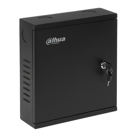
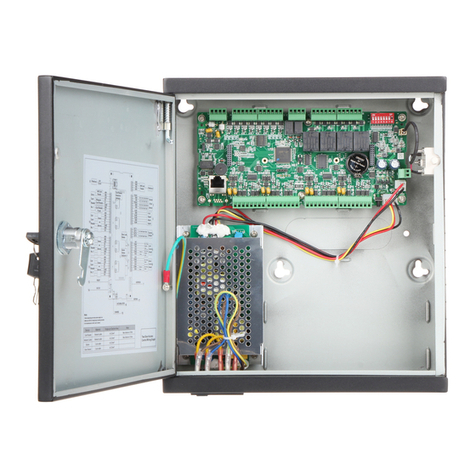
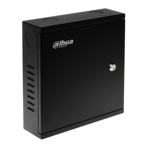
Dahua ARC5408C-W User manual

Network Video Alarm Controller
Quick Start Guide
Version 1.0.0

i
Table of Contents
1 FEATURES AND SPECIFICATIONS...............................................................................1
1.1 Overview ....................................................................................................................1
1.2 Features.....................................................................................................................1
1.3 System Composition................................................................................................1
2 INSTALLATION....................................................................................................................3
2.1 ARC5408B Series....................................................................................................3
2.2 ARC5408C Series....................................................................................................5
2.3 Wiring.......................................................................................................................10
3 WEB Loginand Logout....................................................................................................14
3.1 Login........................................................................................................................14
3.2 Logout......................................................................................................................14
4 Arm/Disarm........................................................................................................................ 15
4.1 Arm/Disarm.............................................................................................................15
4.2 Add and Delete Wireless Device.........................................................................18
4.3 Zone Config ............................................................................................................19
4.4 EmergencyAlarm Config .....................................................................................22
4.5 Siren and Alarm Output Config ...........................................................................23
4.6 Failure Config.........................................................................................................25
4.7 Video Alarm Config ...............................................................................................27
4.8 Event Report Config..............................................................................................29
4.9 Event Info View......................................................................................................31
4.10 Network Config ....................................................................................................31
5 Wireless Alarm Programming Keypad Operation........................................................ 35
5.1 Key...........................................................................................................................35
5.2 Wireless Match Code............................................................................................ 36
5.3 Before Operation ...................................................................................................36
5.4 Arm...........................................................................................................................39
5.5 Disarm.....................................................................................................................39
5.6 Bypass Isolation.....................................................................................................39
5.7 Zone Setup .............................................................................................................40
5.8 Other Setup ............................................................................................................41
5.9 COM Setup.............................................................................................................42
5.10 Output Setup ........................................................................................................43
5.11 View System Status ............................................................................................44
Appendix1Contact ID Event Code....................................................................................47

ii
Welcome
Thank you for purchasing our network video alarm controller!
This quick start guide will help you become familiar with our network video alarm controller in a
very short time.
Before installation and operation, please read the following safeguard and warning carefully!
Model
ARC5408B and ARC5408C

iii
Important Safeguard and Warning
1.Electrical safety
All installation and operation here should conformto your local electrical safety codes.
The product must be grounded to reduce the risk of electric shock.
We assume no liability or responsibility for all the fires or electric shock caused by improper
handling or installation.
2.Transportation security
Heavy stress, violent vibration or water splash are not allowed during transportation, storage and
installation.
3.Installation
Keep upwards. Handle with care.
Do not apply power to the alarmcontroller before completing installation.
Do not place objects on the alarm controller.
4.Qualified engineers needed
All the examination and repair work should be done by the qualified service engineers.
We are not liable for any problems caused by unauthorized modifications or attempted repair.
5.Environment
The alarm controller should be installed in a cool, dry place away from direct sunlight,
inflammable, explosive substances and etc.
This series product shallbe transported, storage and used in the environment ranging from -10℃
to 55 ℃.
6. Accessories
Be sure to use all the accessories recommended by manufacturer.
Before installation, please open the package and check all the components are included.
Contact your local retailer ASAP if something is broken in your package.
Before Start
About Alarm System
For the alarm system consists of the network alarm controller, though it has stable and reliable
performance, it may become null in the following situations:
The protection zone the intruder entering has not enabled the arm function or the intruder
has enough knowledge to disable the system.
The siren device installation position is not right; it does not have the warning function.
The detector is null when there is an alarm outage and etc.
The detector is not in the proper position and can not detect the corresponding zone.
System can not generate an alarm when there is something wrong with the alarm signal
transmission system (the service is disabled, there is malicious attack and etc).

iv
The device is null resulting from non-schedule maintenance of the alarm system.
About Installation Notice
The installation engineers are recommended to check the system regularly such as once a
month. It is to guarantee systemlong-termstable operation.
The installation engineers are recommended to test the system regularly such as once a
week.
Please arrange some training classes for the end-user. It is to keep them familiar with the
system.
System Test Notice
After the installation, you can connect to the AC/DC power to test.
You can test the all functions of the alarm controller after you complete all programming
work.

1
1 FEATURES AND SPECIFICATIONS
1.1 Overview
This series product integrates on-off alarminput and output, and video processing as one multi-
functional video alarm controller. It supports protection zone alarm, wireless remote arm/disarm,
keypad arm/disarm, emergency alarm, video preview authority management, alarm can trigger
pop-up video for you to recheck, video alarm and etc. It can be used in many environments such
as bank, school, store, residential district. It can perfectly work with the alarm and surveillance
solutions when there is an alarm operation and management platform.
1.2 Features
This series product has the following features:
8-ch programming wired zone, 32-ch wireless zone, 1-ch relay control output can extend to
9-ch output.
4-ch 720P analog HDCVI or 4-ch 720Pnetwork video input, may achieve alarm video review
and motion, video loss, video tampering intelligent analytic, meantime support video local
storage and playback.
1-ch audio input, 1-ch talk input and A/V reuse, 1-ch audio output and talk output reuse.
8-ch wireless alarm programming keypad or 8-ch wires alarm programming keypad, 16
wireless remote controls, may use keypad, remote control, smart phone APP to arm/disarm.
Set plan to auto complete arm/disarm.
Alarm event support report in SMS (-C/-E/-CW/-EWmodels)
Main power outage detection and alternate power in place, low battery detection.
Max of 1024 alarm events and failure event records plus 512 system logs.
100 web users, 23 keypad users, 3-level right management: 1 administrator, 1 installer, 21
operator.
1-ch 12V DC 1A AUX output and 2-ch 12V DC/500mA AUX output (1-ch controllable, used
in siren output)
2-ch RS485, 1-ch extension alarm output (i.e. ARM708), 1-ch alarm programming keypad.
1-ch USB and 1-ch 2.5 inch Sata hard disk.
Multiple backup alarm info transmission channel, support PSTN public tel network, TCP/IP
network, 3G network.
2-ch call center, 2-ch network call center (auto registration, static IP).
1.3 SystemComposition
Video Video Alarm Controller and camera, detector, keypad, siren, audio device, PSTN and
monitor, WEB client form a comprehensive linkage alarm system. The system basic connection
figure is in Figure 1- 1.
2
Figure 1- 1

3
2 INSTALLATION
2.1 ARC5408BSeries
2.1.1 Appearance
Video alarm controller appearance is in Figure 2-1.
Figure 2-1
2.1.2 Battery and HDD Installation
To install battery:
Step 1. Tie the two lines symmetrically and pull through pedestal, see Figure 2-2.
Figure 2-2
Step 2. Place battery on the tied line.Tie the battery tightly via the lines, cut the extra part of lines.
Step 3. Insert battery and lines into battery port on device, see Figure 2-3.

4
Figure 2-3
2.1.3 Install HDD
To install HDD:
Step 1. Please use 2.5 inch HDD, fix it on pedestalwith screwdriver.
Step 2. Insert HDD port on motherboard, see Figure 2-4.
Figure 2-4
2.1.4 Wall Mount
The device supports wall mount and desktop placement.
To mount on wall:
Step 1. Open device package, take out plastic expansion bolt and self-tapping screw.

5
Step 2. Dig two holes on wall with distance of 184mm in between. Insert the plastic expansion
bolt and fasten self-tapping screw.
Step 3. Hand the device on the screw.
Figure 2-5
2.2 ARC5408CSeries
2.2.1 Appearance
Video alarm controller appearance is in Figure 2-6.
Figure 2-6

6
2.2.2 Battery Installation
To install battery:
Step 1. Place battery in the case, position as in Figure 2-7.
Figure 2-7
Step 2. Insert one end of battery line into battery, and insert the other end of battery into external
backup power port, see Figure 2-8.
Figure 2-8
2.2.3 PowerAdaptor Installation
Step 1. Refer to Figure 2-9, knock off battery cover.

7
Figure 2-9
Step 2. Place power adaptor inside controller, and adaptor port faces power out hole on case.
Insert power line into power port on the controller, see Figure 2-10.
Figure 2-10
2.2.4 Install HDD
To install HDD:
Step 1. Inside the controller, insert 18.8MM screw, see Figure 2-11.

8
Figure 2-11
Step 2. Place anti-knock ring into the four slots of HDD bracket, and HDD screw hole faces hole
on bracket, fasten anti-knock ring screw, see Figure 2-12.
Figure 2-12
Step 3. Fix HDD with well installed bracket into the controller, see Figure 2-13.

9
Figure 2-13
Step 4. Insert one end of HDD line into hardware, and insert the other end into HDD power port
and data port on controller, see Figure 2-14.
Figure 2-14
2.2.5 Wall Mount
The device supports wall mount and desktop placement.

10
To mount on wall:
Step 1. Open device package, take out plastic expansion bolt and self-tapping screw.
Step 2. See Figure 2-15, dig hole on wall, insert the plastic expansion bolt and fasten self-
tapping screw.
Step 3. Hand the device on the screw.
Figure 2-15
2.3 Wiring
2.3.1 Port
Figure 2-16
No.
Name
Note
○
1
Power port
14.5V power supply
○
2
Battery port
Connect to 12V DC 7AH,lead-
acid battery
○
3
Siren port
Connect to siren
○
4
AUX power output
AUX1 connect to 12V 1A AUX
power;
AUX2 connect to 12V 500mA
○
9
○
8
○
7
○
5
○
16
○
15
○
14
○
13
○
10
○
11
○
2
○
3
○
1
○
4
○
6
○
12
○
17

11
No.
Name
Note
AUX power, used for detector or
alarm keypad power supply
○
5
Sensor port
Support 5-ch sensor connection
○
6
LAN
Ethernet port
○
7
VGA port
Connect to VGA display
○
8
Audio output port
RCA audio output, talk output
○
9
Video input port
4-ch video input
○
10
GND
Grounding
○
11
Audio input port
4-ch audio input
○
12
USB port
Mouse
○
13
Alarm output port
1-ch relay output
○
14
Sensor port
3-ch sensor connection
○
15
RS485 port
A1B1 to alarm programming
keypad
A2B2 to extension alarmoutput
○
16
Telephone port
To user phone
○
17
User line port
To resident phone line
2.3.2 Remote Control Key
See Figure 2-17.
Figure 2-17
Note:
Press all arm button, after indicator is OFF immediately press emergency alarm button, to
out alarm.

12
Press home arm button, after indicator is OFF immediately press emergency alarm button,
to instantly arm.
2.3.3 PowerLine
Battery and DC power supply wirings are shown in Figure 2-18.
Figure 2-18
Note:
Every 3-5 year, change the lead-acid battery.
AUX power supply output 1 and AUX power supply output 2 has voltage change range when not
connecting to loading output:
1). When main power supply is in place, voltage is 14V not connecting to loading output.
2). When main power supply is not in place, uses battery, voltage change range is 9V~13V not
connecting to loading output.
2.3.4 Sensor Wiring
Sensor wiring is shown in Figure 2-19.
Figure 2-19

13
Note:
Tail wire resistance is connection close to sensor end.
Before arming, you must configure sensor type in zone setup, as NO and NC, see Ch 4.3.1.
2.3.5 Alarm Output Wiring
Alarm output wiring is shown in Figure 2-20.
Figure 2-20

14
3 WEB Login and Logout
3.1 Login
Before login, make sure the device is plugged to power and boot up.
Step 1. Open IE and input alarm controller address in the address column. For example, if your
alarm controller IP is 192.168.1.108, then please input http:// 192.168.1.108 in IE address
column. See Figure 3- 1.
Figure 3- 1
Note:
Before first login, make sure your PC and the controller are in the same network segment.
Please be aware that the initial IP of device is 192.168.1.108.
When first login, system shows control installation page, you shallfollow instructions to install
control unit.
Step 2. Please input your user name and password.
Default factory name is admin and password is admin.
Step 3. Select “LAN” or “WAN” as login method.
Note:
The following takes LAN operation as an example.
Step 4. Click Login. System enters WEB homepage.
3.2 Logout
In alarmcontroller WEB page, select Logout tab to exit.
Note:
You must wait about 1 minute before you can login again.

15
4 Arm/Disarm
4.1 Arm/Disarm
4.1.1 Before Arming
1. Check wiring at each part and external devices connected.
2. Confirm whether wireless device has been successfully coded wirelessly to controller.
3. Confirm whether zone parameter is set correctly.
4. Arm all once, check whether zone is abnormal. If there is abnormal, you will see prompt as
in Figure 4- 1.
Figure 4- 1
Now you can manually check sensor, and solve abnormality, or force it to arm without
solving abnormality.
4.1.2 WEB Disarm
4.1.2.1Arm
You can arm zone of alarm controller.
Step 1. Select SETUP>Zone Management>Arm/Disarm Zone. See Figure 4- 2.
Figure 4- 2
This manual suits for next models
1
Table of contents
Other Dahua Controllers manuals

Dahua
Dahua ASC1202C-D User manual

Dahua
Dahua DHI-ASC1204C User manual

Dahua
Dahua DHL460UTS-E User manual

Dahua
Dahua DHI-ASC1204B User manual

Dahua
Dahua VI0401HD-DC3000 User manual

Dahua
Dahua DHI-ARC3008C User manual

Dahua
Dahua DHI-ACS2204C-H User manual

Dahua
Dahua DHI-VTO1210C-X User manual

Dahua
Dahua DHI-ARC3008C User manual

Dahua
Dahua UTC User manual
Popular Controllers manuals by other brands

dropController
dropController V3 manual

Viking
Viking VC-1000 Technical practice

Microchip Technology
Microchip Technology MIC2125 General description

Dometic
Dometic FT7000SEP installation manual

Chamberlain
Chamberlain LA400UL Wiring diagram

Mitsubishi Electric
Mitsubishi Electric Melsec-Q172DCPU user manual