Dahua VTA2302A User manual

Emergency Call Terminal (VTA2302A)
Quick Start Guide
V1.0.0

I
Foreword
General
This manual introduces the installation, functions and operations of the Emergency Call
Terminal (hereinafter referred to as "the Terminal").
Safety Instructions
The following categorized signal words with defined meaning might appear in the manual.
Signal Words
Meaning
DANGER
Indicates a high potential hazard which, if not avoided, will result
in death or serious injury.
WARNING
Indicates a medium or low potential hazard which, if not
avoided, could result in slight or moderate injury.
CAUTION
Indicates a potential risk which, if not avoided, could result in
property damage, data loss, lower performance, or
unpredictable result.
TIPS
Provides methods to help you solve a problem or save you time.
NOTE
Provides additional information as the emphasis and
supplement to the text.
Revision History
Version
Revision Content
Release Time
V1.0.0
First release.
April 2020
About the Manual
The manual is for reference only. If there is inconsistency between the manual and the
actual product, the actual product shall prevail.
We are not liable for any loss caused by the operations that do not comply with the manual.
The manual would be updated according to the latest laws and regulations of related
jurisdictions. For detailed information, refer to the paper manual, CD-ROM, QR code or our
official website. If there is inconsistency between paper manual and the electronic version,
the electronic version shall prevail.
All the designs and software are subject to change without prior written notice. The product
updates might cause some differences between the actual product and the manual. Please
contact the customer service for the latest program and supplementary documentation.
There still might be deviation in technical data, functions and operations description, or
errors in print. If there is any doubt or dispute, we reserve the right of final explanation.
Upgrade the reader software or try other mainstream reader software if the manual (in PDF

II
format) cannot be opened.
All trademarks, registered trademarks and the company names in the manual are the
properties of their respective owners.
Please visit our website, contact the supplier or customer service if there is any problem
occurring when using the device.
If there is any uncertainty or controversy, we reserve the right of final explanation.

III
Important Safeguards and Warnings
The chapter introduces the proper way of using the Terminal, and danger and property damage
preventions. Before using the Terminal, read this manual carefully. Follow the instructions and
keep this manual properly.
Operating Requirements
Do not place and install the Terminal in an area exposed to direct sunlight or near heat
generating device.
Keep the Terminal away from dampness, dust or soot.
Install the Terminal horizontally or in a stable place to prevent it from falling.
Do not drip or splash liquid onto the Terminal, and make sure that there is no object filled
with liquid on the Terminal to prevent liquid from flowing into it.
Install the Terminal in a well-ventilated place, and do not block the ventilation of the
Terminal.
Use the Terminal within the rated range of power input and output.
Do not dismantle the Terminal arbitrarily.
Transport, use and store the Terminal under the allowed humidity and temperature
conditions.
Power Requirements
Use the battery according to requirements; otherwise it might result in fire, explosion or
inflammation.
When replacing the battery, make sure that the same model is used.
Use the recommended power cables in the region and use them under the rated
specification.
Use the power adapter provided with the Terminal; otherwise you will be liable for possible
personal injuries or device damages.
Use power supply that meets SELV (safety extra low voltage) requirements, and supply
power with rated voltage that conforms to Limited Power Source in IEC60950-1. For
specific power supply requirements, refer to device labels.
Connect the device (I-type structure) to the power socket with protective earthing.
The appliance coupler is a disconnection device. Keep a convenient angle when using it.

1
Table of Contents
Foreword..................................................................................................................................................I
Important Safeguards and Warnings...................................................................................................III
1 Product Overview................................................................................................................................2
Introduction .................................................................................................................................2
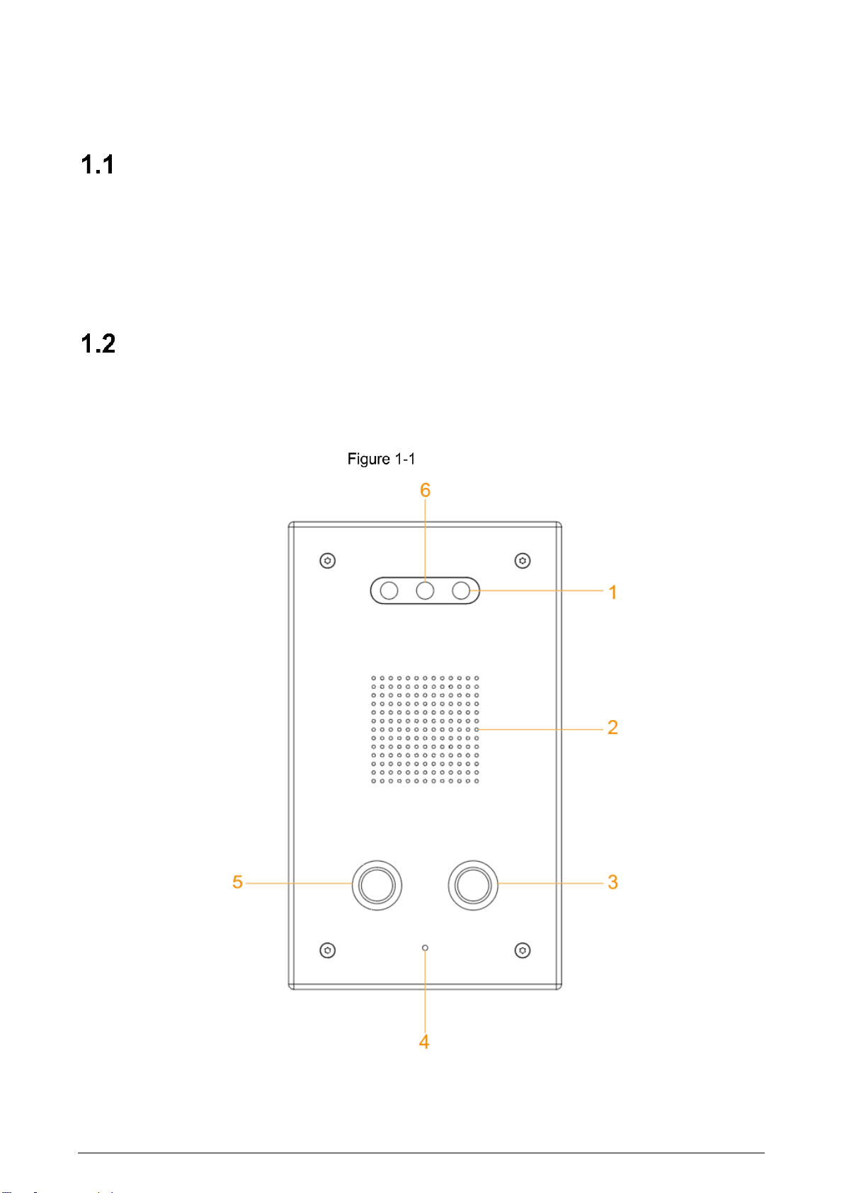
Structure......................................................................................................................................2
1.2.1 Front Panel........................................................................................................................2
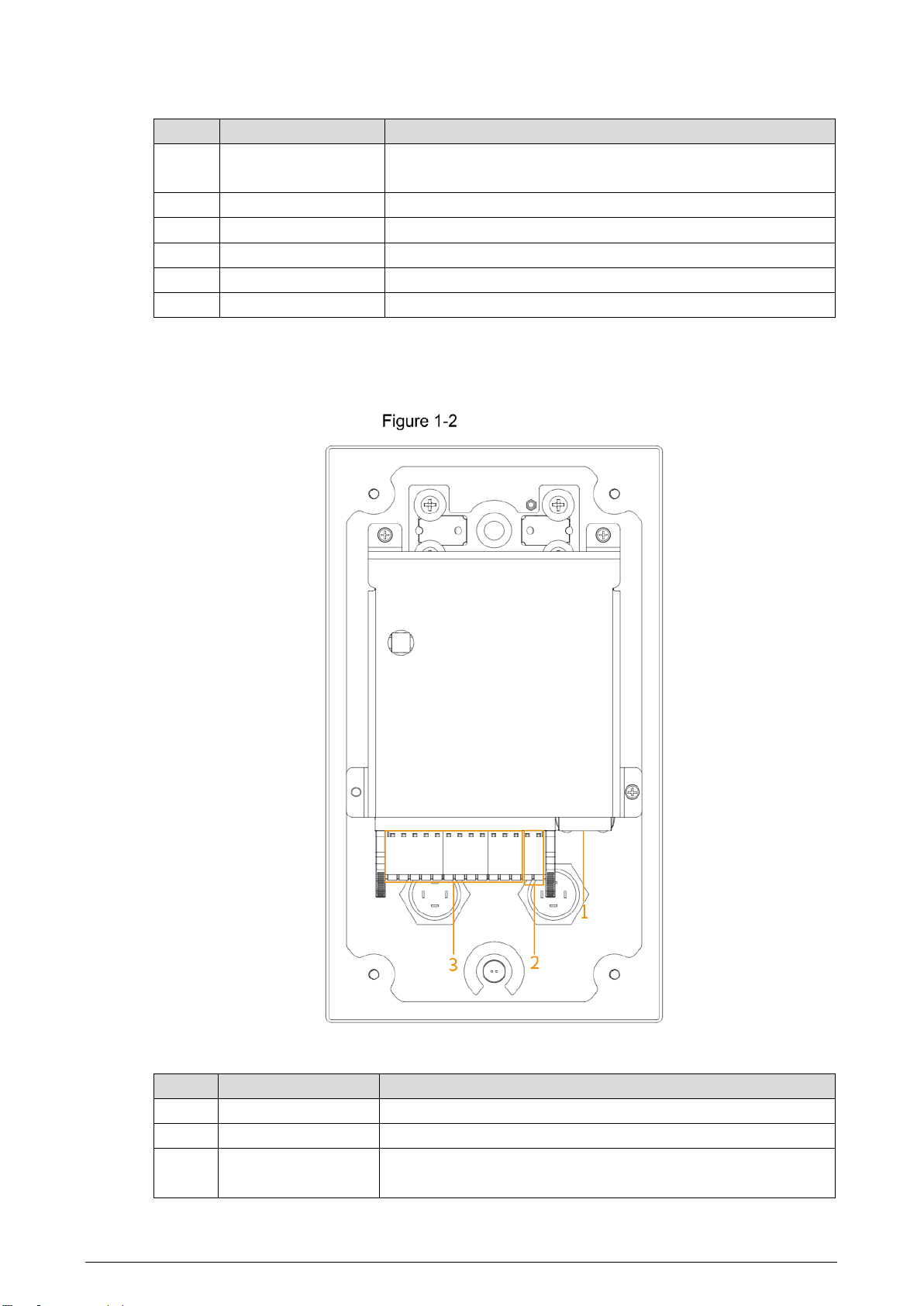
1.2.2 Rear Panel........................................................................................................................3
1.2.3 Device Ports......................................................................................................................4
Typical Networking......................................................................................................................5
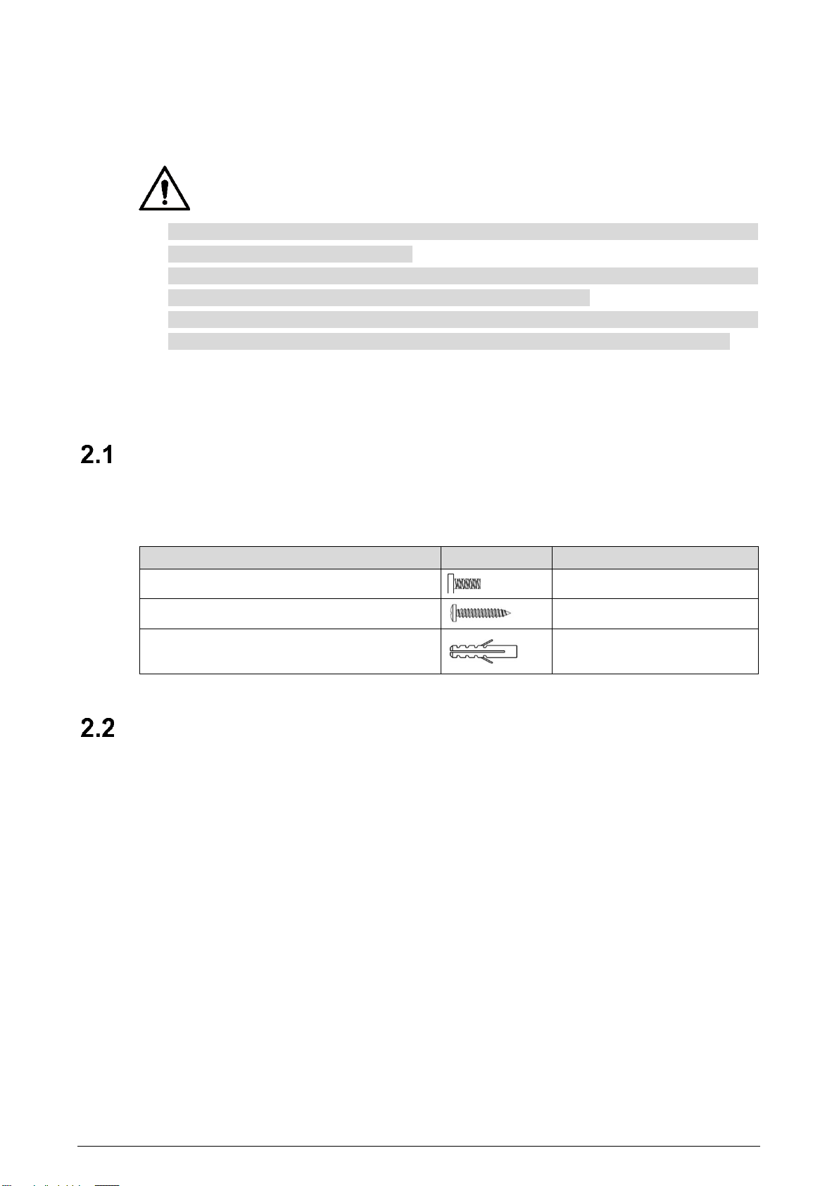
2 Installation ...........................................................................................................................................6
Screws ........................................................................................................................................6
Mounting Plate Dimensions.........................................................................................................6
Procedure....................................................................................................................................7
3 Web Operations...................................................................................................................................9
Initialization .................................................................................................................................9
Login .........................................................................................................................................10
Password Reset........................................................................................................................10
Local Settings............................................................................................................................11
3.4.1 Basic Settings .................................................................................................................11
3.4.2 Video & Audio..................................................................................................................12
3.4.3 System Settings..............................................................................................................14
3.4.4 Alarm Output Settings .....................................................................................................15
3.4.5 Security Management .....................................................................................................15
3.4.6 Onvif User.......................................................................................................................16
Network Settings.......................................................................................................................17
3.5.1 TCP/IP.............................................................................................................................17
3.5.2 Firewall............................................................................................................................18
3.5.3 Register...........................................................................................................................20
Logout .......................................................................................................................................21
Restart.......................................................................................................................................21
Restoring to Factory Settings....................................................................................................21
4 Basic Functions.................................................................................................................................22
Calling.......................................................................................................................................22
Monitoring and Listening...........................................................................................................22
Light Compensation ..................................................................................................................22
Tampering Alarm .......................................................................................................................22
Alarm Linkage............................................................................................................................22
5 FAQ.....................................................................................................................................................23
Cybersecurity Recommendations ..................................................................................24

2
1 Product Overview
Introduction
The Terminal can be connected with the management platform and master station (VTS) to
provide emergency calling, voice broadcasting, video monitoring, and more. It is applicable to
schools, banks, industrial parks, apartments, office buildings and other places. And it can be
configured on the web interface.
Structure
1.2.1 Front Panel
Front panel

3
Table 1-1 Front panel description
No.
Name
Description
1
Illuminator
When the light is insufficient and the Terminal is monitored
or calling, the illuminator is turned on automatically.
2
Speaker
Outputs audio.
3
Service button
Calls the management center.
4
Microphone
Inputs audio.
5
SOS button
Sends alarms to the management center.
6
Camera
Capture videos.
1.2.2 Rear Panel
Rear panel
Table 1-2 Rear panel description
No.
Name
Description
1
Network port
Insert network cable (RJ-45 connector).
2
Power port
Connect 12V DC power supply.
3
Device ports
For audio input and output, alarm input and output, RS-485,
and so on. For details, see "1.2.3 Device Ports."

4
1.2.3 Device Ports
Device ports
Table 1-3 Device ports description
No.
Name
No.
Name
1
MIC
6
Power input
2
Alarm input 1
7
RS-485
3
Alarm input 2
8
Reserved ports
4
Alarm output 1
9
Active speaker
5
Alarm output 2
—
—

5
Typical Networking
Networking
The master station in the networking is optional.

6
2 Installation
Do not install the Terminal in places with condensation, high temperature, grease, dust,
chemical corrosion, or direct sunlight.
In case of abnormality after powering on, cut off the power supply immediately, and then
pull out the network cable. Power on again after troubleshooting.
Engineering installation and debugging shall be done by professional teams. Do not
dismantle or repair arbitrarily in case of device failure. Contact after-sales department.
Surface mount is supported, and rear cable outlet and bottom cable outlet are reserved on the
mounting plate.
Screws
Before installing the Terminal, check the screws in the accessory package.
Table 2-1 Screws
Name
Figure
Quantity
M3X8 hexalobular socket screw
4
ST3×18 self-tapping screw
4
Expansion bolt
4
Mounting Plate Dimensions
Before installing the Terminal, see the mounting plate dimensions first to provide enough
installation space.

7
Mounting plate dimensions (mm [inch])
Procedure
Drill 4 holes on the wall according to the screw holes on the mounting plate, and put the
expansion bolts into the holes.
Fix the mounting plate on the wall with the ST3×18 self-tapping screws.
Apply sealant between the mounting plate and the wall, and to cover the cable outlets.
Fix the Terminal to the mounting plate with M3X8 hexalobular socket screws.

8
Installation
Table 2-2 Installation component
No.
Name
No.
Name
1
M3X8 hexalobular socket screw
4
Bottom cable outlet
2
Emergency Call Terminal
5
Rear cable outlet
3
ST3×18 self-tapping screw
6
Mounting plate

9
3 Web Operations
Initialization
For first-time login, or login after restoring to factory settings, you need to initialize the
Terminal.
The IP address is 192.168.1.108 by default. Make sure that the PC and the Terminal are in
the same network segment.
Enter the IP address of the Terminal in the address bar.
Enter and confirm the password according to the on-screen prompts, and then click
Next. Password setting
Select the check box, enter the email address, and then click Next.
Password protection

10
Click OK. Initialization completed
Login
Enter the IP address of the Terminal in the address bar.
Enter the username and password.
Login interface
Click Login.
Password Reset
If you forget the password when logging in to the web interface, you can reset the password.
Click Forgot password? on the login interface.
If you use IE browser, the system might prompt Stop running the script, click No to
continue to run the script.

11
Click Next, scan the QR code according to the on-screen prompts, and you will get the
security code.
In the Security Code box, enter the security code received in your provided mailbox.
Enter the security code
Click Next.
Enter and confirm the new password.
The password should consist of 8 to 32 non-blank characters and contain at least two
types of characters among uppercase, lowercase, number, and special character
(excluding ' " ; : &). The confirming password should be the same as the new password.
Set a strong password according to the prompt of password strength.
Resetting password
Click Save.
Local Settings
3.4.1 Basic Settings
Set the name of the Terminal for easy identification.
Select Local Setting > Basic on the web interface.
Enter the device name.

12
Device name setting
Click Confirm.
3.4.2 Video & Audio
You can set the brightness, contrast, hue, saturation and scene mode of the monitoring screen,
and adjust the volume of the Terminal.
Select Local Setting > Video & Audio on the web interface.
If the plug-in has not been installed, follow on-screen instructions to install it.
Configure parameters. Video & audio

13
Table 3-1 Video & audio parameter description
Parameter
Description
Video Format
The Terminal supports 720P (1280 ×720), WVGA (800 ×480), D1
(720 ×576), and CIF (352 ×288). You can select as needed.
Frame Rate
The number of frames per second in a video. The higher the frame
rate is, the more clear and smooth the video will be.
Bandwidth
Select the bandwidth according to the network the Terminal is
connected to.
Brightness
The overall brightness of the image.
The larger the value is, the brighter the image will become.
The image might be white if the value is too large.
Contrast
The ratio of black to white in the image. The larger the value is, the
richer the image color.
If the value is too large, the dark area becomes darker and the
bright area is likely to be overexposed.
The image might be greyish if the value is too small.
Hue
Adjust the color of the image. The larger the value, the darker the
color.
Saturation
Adjust the image vividness. The larger the value, the more vivid
the image. This value does not affect the overall brightness of
image.
Gamma
Change the image brightness and contrast in a non-linear way.
The larger the value, the brighter the image.
Mirror
Flip the image horizontally.
Flip
Flip the image vertically.
Display Time
Display the time at the top left corner of the monitoring screen.
Scene Mode
The overall tone of the image varies with the scene modes.
Disabled: No mode is set.
Auto: Automatically adjust the scene mode to make the
image color normal according to the light reaching the sensor.
This mode is selected by default.
Sunny: The image tone is decreased in this mode.
Night: The image tone is increased in this mode.
Day/Night Mode
This mode affects the illumination of the Terminal.
Auto: Automatically adjust the mode to make the image color
normal according to the light reaching the sensor.
Color: The image is colored.
B/W: The image is black and white.
Backlight Mode
Select the appropriate compensation mode according to the actual
conditions.
When human faces are in the backlight, it is recommended to
select WDR.
Disabled: No compensation is made.
BLC: Backlight compensation corrects areas with extremely

14
Parameter
Description
high or low levels of light to maintain a normal and usable
level of light for the object in focus.
WDR: The system dims bright areas and compensates dark
areas to ensure the clarity of all areas according to the lighting
conditions.
HLC: The system constrains bright areas and reduces halo
size to dim the overall brightness.
Video Standard
Select PAL or NTSC as needed.
PAL: The frame rate is 25 fps by default.
NTSC: The frame rate is 30 fps by default.
Microphone
Volume/Speaker
Volume
Adjusts the volume of the microphone or speaker.
3.4.3 System Settings
You can set the time zone, system time, DST type and NTP timing.
Select Local Setting > System on the web interface.
Configure parameters. System settings
Table 3-2 System settings parameters
Parameter
Description
Date Format
Select the display format of the date from YYYY-MM-DD,
MM-DD-YYYY and DD-MM-YYYY.
Time Format
Select the time format from 24-Hour and 12-Hour.
Time Zone
Select the local time zone.
System Time
Set the system time manually.
Click Sync PC to synchronize the system time with the PC time.
DST setting
Select the ON check box to enable DST.
1. Select Date or Week as the DST Type.
2. Set the Start Time and End Time.

15
Parameter
Description
NTP setting
Set NTP time synchronization.
1. Select the NTP Enable check box.
2. Configure parameters.
NTP Server: Enter the IP address of the time server for the Terminal
to synchronize time.
Port: Enter the port number of the time server.
Interval: Enter the interval at which the time is synchronized.
Maintenance
Set the auto maintenance time of the system.
SSH
You can enable SSH (Secure Shell) authentication to perform safety
management. The function is disabled by default.
Click Save.
3.4.4 Alarm Output Settings
After the alarm output is enabled, when the Terminal initiates a call, the alarm output relay can
output the alarm signal.
Select Local Setting > Alarm Output on the web interface.
Configure parameters. Alarm output settings
Table 3-3 System settings parameters
Parameter
Description
Channel
The Terminal has two alarm outputs. Select the alarm output channel
according to the alarm device you have installed.
Alarm Type
Alarm Light is selected by default.
Click Save.
3.4.5 Security Management
You can configure system service to ensure secure management.
Select Local Setting > Security on the web interface.
Configure parameters.

16
Security management
Table 3-4 Security management parameter description
Parameter
Description
CGI Enable
Enabled by default. The Terminal can connect with other network
video products through this protocol.
CGI (Common Gateway Interface) is an interface between external
programs and web server.
Onvif Enable
Password Reset
Enabled by default to allow password resetting and setting reserved
email address. After successful setting, you can reset the password
by clicking Forgot password? on the login interface.
If the function is disabled, you can only reset the password after
restoring the Terminal to factory settings by pressing the reset button
on the device.
Authentication
Mode
Select the anthentication mode from Security Mode and Compatible
Mode.
Click Save.
3.4.6 Onvif User
The function is mainly for acquiring streams through Onvif protocol, and the information of the
Onvif user needs to be validated. You can add or delete Onvif users, and modify their
passwords. The Onvif user is admin by default.
Preparation
On the web interface, select Local Setting > Security, and then select the Onvif Enable
check box.
Procedure
Select Local Setting > Onvif User on the web interface.
Click Add.
Enter the username and password, and then confirm the password you entered.
Table of contents
Popular Emergency Phone manuals by other brands

LogicMark
LogicMark CaretakeSentry 40914 Quick install guide

Mytrex
Mytrex MXD3G user manual

Safeline
Safeline MX2 installation manual

Rath
Rath 2100-CS9 Installation and operation manual

AUDIOLINE
AUDIOLINE BIGTEL 49 PLUS operating instructions

Cooper safety
Cooper safety VoCall CFVCCM9 Compact Master Installation, commissioning and maintenance manual