Daikin DP3G Series User manual

1
Ax this manual and
Users Information Manual adjacent to the unit.
DP3G 13.4 SEER2 “M” SERIES With R-410A
Single PAckAge gAS-electRic heAting & cooling Unit
O
NLY
PERSONNEL
THAT
HAVE
BEEN
TRAINED
TO
INSTALL
,
ADJUST
,
SERVICE
OR
REPAIR
(
HEREINAFTER
, “
SERVICE
”)
THE
EQUIPMENT
SPECIFIED
IN
THIS
MANUAL
SHOULD
SERVICE
THE
EQUIPMENT
. T
HE
MANUFACTURER
WILL
NOT
BE
RESPONSIBLE
FOR
ANY
INJURY
OR
PROPERTY
DAMAGE
ARISING
FROM
IMPROPER
SERVICE
OR
SERVICE
PROCEDURES
. I
F
YOU
SERVICE
THIS
UNIT
,
YOU
ASSUME
RESPONSIBILITY
FOR
ANY
INJURY
OR
PROPERTY
DAMAGE
WHICH
MAY
RESULT
. I
N
ADDITION
,
IN
JURISDICTIONS
THAT
REQUIRE
ONE
OR
MORE
LICENSES
TO
SERVICE
THE
EQUIPMENT
SPECIFIED
IN
THIS
MANUAL
,
ONLY
LICENSED
PERSONNEL
SHOULD
SERVICE
THE
EQUIPMENT
. I
MPROPER
INSTALLATION
,
ADJUSTMENT
,
SERVICING
OR
REPAIR
OF
THE
EQUIPMENT
SPECIFIED
IN
THIS
MANUAL
,
OR
ATTEMPTING
TO
INSTALL
,
ADJUST
,
SERVICE
OR
REPAIR
THE
EQUIPMENT
SPECIFIED
IN
THIS
MANUAL
WITHOUT
PROPER
TRAINING
MAY
RESULT
IN
PRODUCT
DAMAGE
,
PROPERTY
DAMAGE
,
PERSONAL
INJURY
OR
DEATH
.
INSTALLATION INSTRUCTIONS
These installation instructions cover the outdoor installation
of self contained package air conditioners and heating units.
See the Specication Sheets applicable to your model for
information regarding accessories.
*NOTE: Please contact your distributor or our website for
the applicable Specication Sheets referred to in this manual.
This Forced Air Central Unit Design Complies With Require-
ments Embodied In The American National Standard / Na-
tional Standard of Canada Shown Below.
ANSI Z21.47•CSA-2.3 Central Furnaces.
RECOGNIZE THIS SYMBOL AS A SAFETY PRECAUTION.
Our continuing commitment to quality products may mean a change in specications without notice.
19001 Kermier Road, Waller, TX 77484
www.daikincomfort.com
©2022
IOD-3024
06/2022
WARNING
DO NOT BYPASS SAFETY DEVICES

2
Index
REPLACEMENT PARTS..................................................................... 3
ORDERING PARTS .................................................................. 3
SAFETY INSTRUCTIONS................................................................... 3
TO THE INSTALLER.................................................................. 3
GENERAL INFORMATION................................................................ 5
TRANSPORTATION DAMAGE ................................................. 5
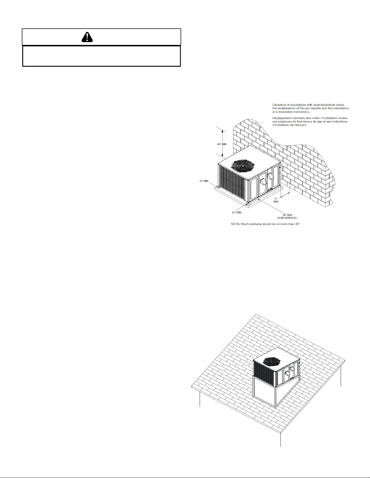
UNIT LOCATION .............................................................................. 6
ALL INSTALLATIONS: .............................................................. 6
GROUND LEVEL INSTALLATIONS ONLY: ................................. 6
ROOFTOP INSTALLATIONS ONLY:........................................... 6
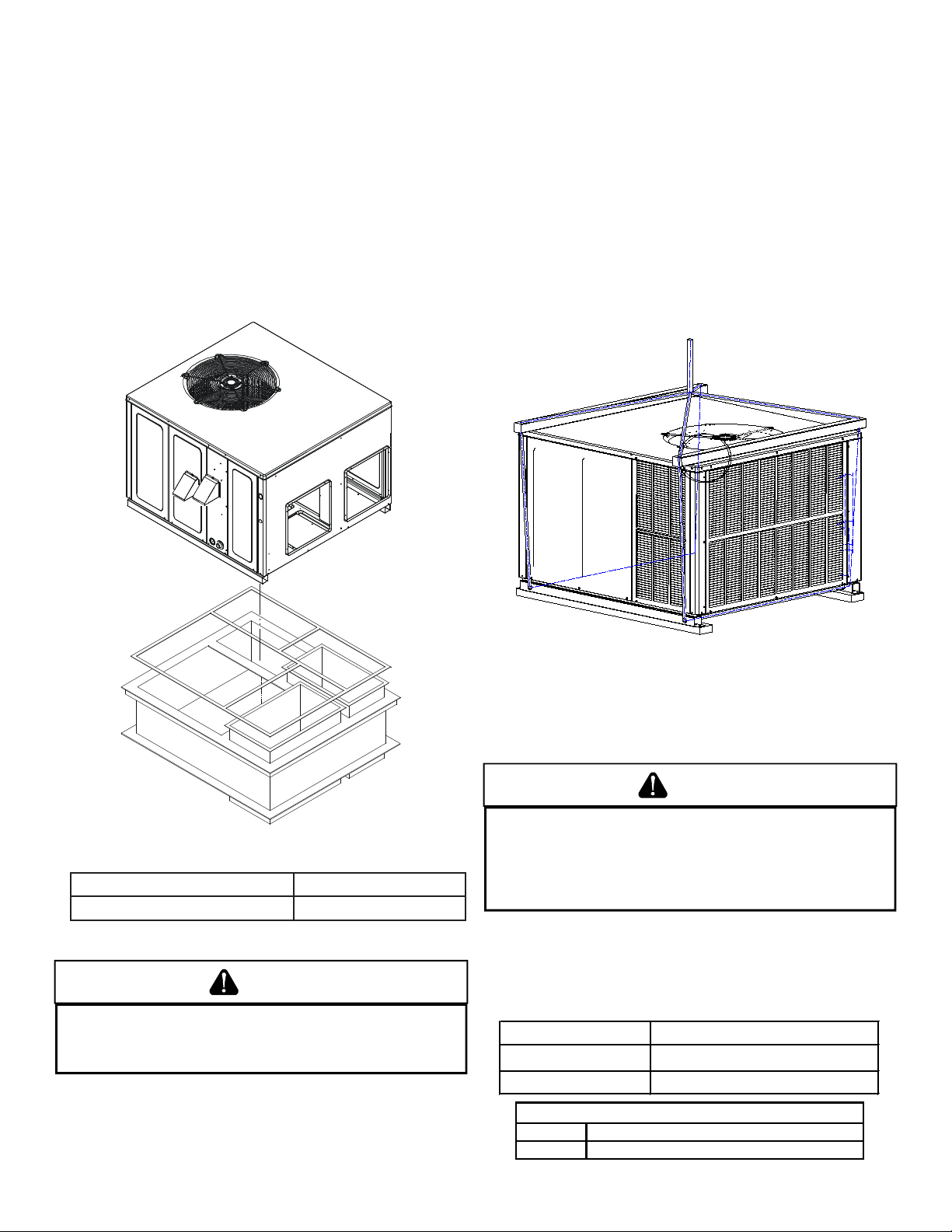
ROOF CURB INSTALLATIONS ONLY: ....................................... 7
RIGGING DETAILS............................................................................ 7
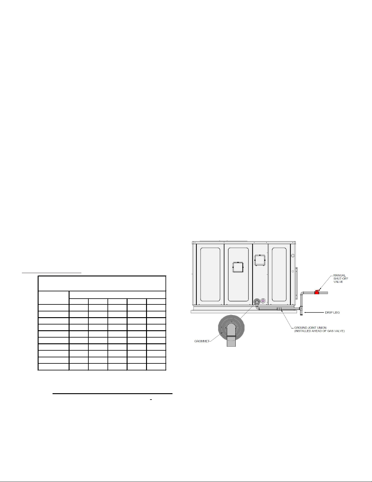
GAS PIPING ..................................................................................... 7
.......... 8
PIPING.................................................................................... 8
GAS PIPING CHECKS .............................................................. 9
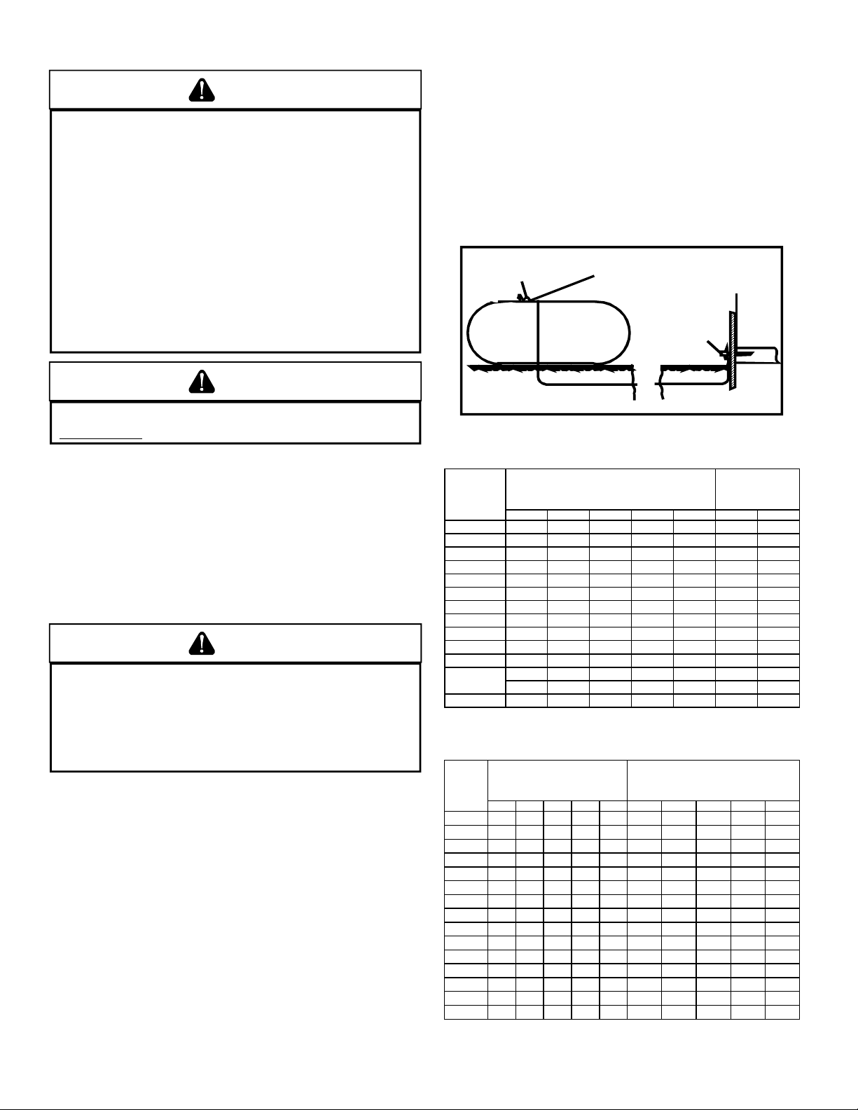
PROPANE GAS INSTALLATIONS ...................................................... 9
TANKS AND PIPING................................................................ 9
ELECTRICAL WIRING..................................................................... 10
THERMOSTAT LOCATION ..................................................... 10
......... 10
UNIT VOLTAGE...................................................................... 11
CIRCULATING AIR AND FILTERS.................................................... 11
AIRFLOW CONVERSION ....................................................... 11
DUCTWORK.......................................................................... 12
FILTERS ................................................................................. 12
VENTING ....................................................................................... 12
FLUE HOOD INSTALLATION.................................................. 12
............................... 12
............. 13
CONDENSATE DRAIN .................................................................... 13
CONDENSATE DRAIN CONNECTION .................................... 13
NORMAL SEQUENCE OF OPERATION........................................... 13
HEATING............................................................................... 13
COOLING .............................................................................. 14
FAN ONLY ............................................................................. 14
STARTUP, ADJUSTMENTS, AND CHECKS....................................... 14
HEATING STARTUP .............................................................. 14
GAS SUPPLY PRESSURE MEASUREMENT............................. 15
GAS MANIFOLD PRESSURE MEASUREMENT
AND ADJUSTMENT............................................................... 16
COOLING STARTUP .............................................................. 19
CHECKING SUBCOOLING ..................................................... 19
CHECKING SUPERHEAT ........................................................ 19
TROUBLESHOOTING ..................................................................... 20
IGNITION CONTROL ERROR CODES..................................... 20
ABNORMAL OPERATION - HEATING.................................... 20
ABNORMAL OPERATION - COOLING ................................... 22
MAINTENANCE ............................................................................. 22
FILTER REPLACEMENT OR CLEANING ................................. 22
CABINET FINISH MAINTENANCE......................................... 22
.......... 22
CONDENSER, EVAPORATOR,
..................................... 22
..................... 22
.................... 22
CLEANING FLUE PASSAGES
........................................... 23
.......... 23
CLEANING BURNERS............................................................ 23
ACCESSORIES AND FUNCTIONAL PARTS...................................... 23
SHEET METAL ACCESSORIES ............................................... 23
FUNCTIONAL PARTS............................................................. 24
GENERAL INFORMATION..................................................... 24
BLOWER PERFORMANCE DATA .................................................... 25
IGNITION CONTROL DIAGNOSTIC INDICATOR CHART
.................................................... 29
HEATING TIMING CHART.............................................................. 29
COOLING TIMING CHART ............................................................. 29
IGNITION CONTROL DIAGNOSTIC INDICATOR CHART
........................................................ 30
HEATING TIMING CHART.............................................................. 30
COOLING TIMING CHART ............................................................. 30
..................................................................................... 31
UNIT DIMENSIONS............................................................... 31
WIRING DIAGRAMS...................................................................... 32
HOMEOWNER’S ROUTINE MAINTENANCE.................................. 44
........................................................................... 45

3
REPLACEMENT PARTS
Ordering Parts
When reporting shortages or damages, or ordering repair parts,
give the complete unit model and serial numbers as stamped
on the unit’s nameplate.
Replacement parts for this appliance are available through your
contractor or local distributor. For the location of your nearest
distributor, consult the white business pages, the yellow page
section of the local telephone book or contact:
HOMEOWNER SUPPORT
DAIKIN NORTH AMERICA LLC
19001 KERMIER ROAD
WALLER, TEXAS 77484
855-770-5678
SAFETY INSTRUCTIONS
To The Installer
Before installing this unit, please read this manual to familiarize
yourself on the specic items which must be adhered to,
including maximum external static pressure to unit, air
temperature rise, minimum or maximum CFM and motor speed
connections.
Keep this literature in a safe place for future reference.
WARNING
SHOULD OVERHEATING OCCUR OR T HE GAS S UPPLY FAIL T O SHUT OFF, TURN
OFF THE MANUAL GAS SHUTOFF VALVE EXTERNAL TO T HE F URNACE BEFORE
TURNING OFF THE ELECTRICAL S UPPLY.
WARNING
TO AVOID PROPERTY D AMAGE, P ERSONAL INJURY O R DEATH, D O NOT USE
THIS U NIT IF ANY PART HAS BEEN UNDER WATER. IMMEDIATELY CALL A
QUALIFIED SERVICE TECHNICIAN T O INSPECT THE FURNACE AND T O REPLACE
ANY PART O F THE CONTROL SYSTEM A ND A NY G AS CONTROL H AVING BEEN
UNDER WATER.
WARNING
TO PREVENT THE RISK OF PROPERTY DAMAGE, PERSONAL INJURY, OR DEATH,
DO NOT STORE COMBUSTIBLE MATERIALS OR USE GASOLINE OR OTHER
FLAMMABLE LIQUIDS OR VAPORS IN THE VICINITY OF THIS APPLIANCE.
F
AILURE
TO
FOLLOW
THE
SAFETY
WARNINGS
COULD
RESULT
IN
SERIOUS
INJURY
,
DEATH
OR
PROPERTY
DAMAGE
. N
EVER
TEST
FOR
GAS
LEAKS
WITH
AN
OPEN
FLAME
. U
SE
COMMERCIALLY
AVAILABLE
SOAP
SOLUTION
MADE
SPECIFICALLY
FOR
THE
DETECTION
OF
LEAKS
TO
CHECK
ALL
CONNECTIONS
. A
FIRE
OR
MAY
RESULT
CAUSING
PROPERTY
DAMAGE
,
PERSONAL
INJURY
OR
LOSS
OF
LIFE
.
S
I
L
ES
C
ONSIGNES
D
E
S
É CURITÉ
N
E
S
ONT
P
AS
S
UIVIES
À L
A
L
ETTRE
, C
ELA
P
EUT
E
NTRAÎNER
L
A
M
ORT
, D
E
G
RAVES
B
LESSURES
O
U
D
ES
D
OMMAGES
M
ATÉRIELS
. N
E
J
AMAIS
V
É RIFIER
L
A
P
RÉ SENCE
D
E
F
UITES
D
E
G
AZ
A
U
M
OYEN
D'
UNE
F
LAMME
N
UE
. V
É RIFIER
T
OUS
L
ES
R
ACCORDS
E
N
U
TILISANT
U
NE
S
OLUTION
S
AVONNEUSE
C
OMMERCIALE
C
ONÇ UE
S
PÉ CIALEMENT
P
OUR
L
A
D
ÉTECTION
D
E
F
UITES
. U
N
I
NCENDIE
O
U
U
NE
E
XPLOSION
R
ISQUE
D
E
S
E
P
RODUIRE
, C
E
Q
UI
P
EUT
E
NTRAÎNER
L
A
M
ORT
, D
ES
B
LESSURES
O
U
D
ES
D
OMMAGES
M
ATÉRIELS
.

4
D
Failure To Follow The Steps Outlined Below For Each Appliance
Connected To The Venting System Being Placed Into Operation
Could Result In Carbon Monoxide Poisoning Or Death. The
Following Steps Shall Be Followed For Each Appliance Connected
To The Venting System Being Placed Into Operation, While All
Other Appliances Connected To The Venting System Are Not In
Operation:
1) Seal Any Unused Openings In The Venting System.
2) Inspect The Venting System For Proper Size And Horizontal
Pitch, As Required In The National Fuel Gas Code, Ansi
Z223.1/nfpa 54 Or The Natural Gas And Propane Installation Code,
Csa B149.1 And These Instructions. Determine That There Is No
Blockage Or Restriction, Leakage, Corrosion And Other
Deficiencies Which Could Cause An Unsafe Condition.
3) As Far As Practical, Close All Building Doors And Windows And
All Doors Between The Space In Which The Appliance(s)
Connected To The Venting System Are Located And Other Spaces
Of The Building.
4) Close Fireplace Dampers.
5) Turn On Clothes Dryers And Any Appliance Not Connected To
The Venting System. Turn On Any Exhaust Fans, Such As Range
Hoods And Bathroom Exhausts, So They Are Operating At
Maximum Speed. Do Not Operate A Summer Exhaust Fan.
6) Follow The Lighting Instructions. Place The Appliance Being
Inspected Into Operation. Adjust The Thermostat So Appliance Is
Operating Continuously.
7) Test For Spillage From Draft Hood Equipped Appliances At The
Draft Hood Relief Opening After 5 Minutes Of Main Burner
Operation. Use The Flame Of A Match Or Candle.
8) If Improper Venting Is Observed During Any Of The Above Tests,
The Venting System Must Be Corrected In Accordance With The
National Fuel Gas Code, Ansi Z223.1/nfpa 54 And/or Natural Gas
And Propane Installation Code, Csa B149.1.
9) After It Has Been Determined That Each Appliance Connected
To The Venting System Properly Vents When Tested As Outlined
Above, Return Doors, Windows, Exhaust Fans, Fireplace Dampers
And Any Other Gas-fired Burning Appliance To Their Previous
Conditions Of Use.
E
Si les étapes décrites ci-dessous ne sont pas suivies pour chacun
des appareils raccordés au système de ventilation au moment
de sa mise en marche, cela peut entraîner une intoxication au
monoxyde de carbone ou la mort. Les étapes suivantes doivent
être suivies pour chacun des appareils raccordés au système de
ventilation au moment de sa mise en marche, alors que tous les
autres appareils raccordés au système de ventilation ne sont
pas en marche:
1) Sceller toutes les ouvertures inutilisées du système de
ventilation.
2) Inspecter le système de ventilation afin de vérifier si la taille
et l’inclinaison par rapport à l’horizontale sont conformes aux
exigences du National Fuel Gas Code, ANSI Z223.1/NFPA 54 ou
du Code d’installation du gaz naturel et du propane, CSA B149.1
et à ces instructions. Vérifier qu’il n’y pas d’obstruction ou de
pourraient entraîner une situation dangereuse.
3) Si possible, fermer toutes les portes et fenêtres du bâtiment
ainsi que toutes les portes séparant l’endroit où se trouvent les
appareils raccordés au système de ventilation et less autres
zones du bâtiment.
4) Fermer le registre des foyers.
5) Mettre les sécheuses en marche ainsi que tous les autres
appareils qui ne sont pas raccordés au systéme de ventilation.
Mettre en marche tous les ventilateurs de tirage, comme celui
des hottes de cuisine et des salles de bains, et les régler à la
puissance maximale. Ne pas mettre en marche les ventilateurs
d’été.
6) Suivre les instructions d’allumage. Mettre en marche
l’appareil soumis à l’inspection. Régler le thermostat de manièr
à ce que l’appareil fonctionne en continu.
7) Vérifier la présence de fuite au niveau de l’ouverture du
coupe-tirage des appareils qui en sont dotés après 5 minutes de
fontionnement du brûleur principal. Utiliser la flamme d’une
allumette ou d’une bougie.
8) Si un problème de ventilation est observé pendant l’un des
essaid décrits ci-dessus, des correctifs doivent être apportés au
système de ventilation conformé National Fuel Gas Code, Ansi
Z223.1/nfpa 54 And/or Natural Gas And Propane Installation
Code, Csa B149.1.
9) Une fois qu’il été déterminé que chaque appareil raccordé au
système de ventilation fontionne correctement au moyen des
essais décrits ci-dessus, les portes, les fenêtres, les ventilateurs,
les registres de foyer et tous les autres appareils de combustion
alimentés au gaz doivent être remis dans leur état initial.

5
General Information
WARNING
T
O PREVENT PROPERTY DAMAGE, P ERSONAL I NJURY O R DEATH, DUE T O FIRE,
EXPLOSIONS, SMOKE, S OOT, C ONDENSATION, E LECTRIC SHOCK OR CARBON
MONOXIDE, THIS UNIT MUST B E PROPERLY I NSTALLED, R EPAIRED, O PERATED,
AND MAINTAINED.
This unit is approved for outdoor installation ONLY. Rated
performance is achieved after 20 hours of operation. Rated
performance is delivered at the specied airow. See outdoor
unit specication sheet for split system models or product
specication sheet for packaged and light commercial models.
Specication sheets can be found at www.daikincomfort.com
for Daikin brand products. Within the website, please select
the residential or commercial products menu and then select
the submenu for the type of product to be installed, such as air
conditioners or heat pumps, to access a list of product pages
that each contain links to that model’s specication sheet.
To assure that your unit operates safely and eciently, it
must be installed, operated, and maintained in accordance
with these installation and operating instructions, all local
building codes and ordinances, or in their absence, with the
latest edition of the National Fuel Gas Code NFPA54/ANSI
Z223.1 and National Standard of Canada CAN/CSA B149
Installation Codes.
The heating and cooling capacities of the unit should be greater
than or equal to the design heating and cooling loads of the
area to be conditioned. The loads should be calculated by an
approved method or in accordance with A.S.H.R.A.E. Guide or
Manual J - Load Calculations published by the Air Conditioning
Contractors of America.
Obtain from:
American National Standards Institute
25 West 43rd Street, 4th Floor
New York, NY 10036
Transportation Damage
Check the carton upon arrival for external damage. If damage
is found, a request for inspection by carrier agent should be
made in writing immediately.
Carefully inspect the unit for damage including damage to
the cabinetry. Any bolts or screws which may have loosened
in transit must be retightened. In the event of damage, the
receiver should:
1. Make notation on delivery receipt of any visible
damage to shipment or container.
2. Notify carrier promptly and request an inspection.
3. In case of concealed damage, carrier should be
notied as soon as possible-preferably within 5 days.
4. File the claim with the following supporting documents:
a. Original Bill of Lading, certied copy, or indemnity
bond.
b. Original paid freight bill or indemnity in lieu thereof.
c. Original invoice or certied copy thereof, showing
trade and other discounts or reductions.
d. Copy of the inspection report issued by carrier
representative at the time damage is reported to the
carrier. The carrier is responsible for making prompt
inspection of damage and for a thorough investigation
of each claim. The distributor or manufacturer will
not accept claims from dealers for transportation
damage.
NOTE: When inspecting the unit for transportation damage,
remove all packaging materials. Recycle or dispose of the
packaging material according to local codes.
B10259-216
CO can cause serious illness including permanent brain
damage or death.
Advertencia especial para la instalación de calentadores ó manejadoras
de aire en áreas cerradas como estacionamientos ó cuartos de servicio.
B10259-216
El monóxido de carbono puede causar enfermedades severas
como daño cerebral permanente ó muerte.
Las emisiones de monóxido de carbono pueden circular a través
del aparato cuando se opera en cualquier modo.
B10259-216
RISQUE D'EMPOISONNEMENT AU
Le monoxyde de
des
carbone peut causer des maladies graves telles que
dommages permanents au cerveau et meme la mort.
Cette ventilation est nécessaire pour éviter le danger d'intoxication
au CO pouvant survenir si un appareil produisant du monoxyde
de carbone continue de fonctionner au sein de la zone confinée.

6
Unit location
WARNING
TO PREVENT POSSIBLE E QUIPMENT D AMAGE, P ROPERTY DAMAGE, PERSONAL
INJURY O R DEATH, T HE F OLLOWING BULLET POINTS M UST BE O BSERVED
WHEN INSTALLING THE UNIT.
All Installations:
• For proper ame pattern within the heat exchanger
and proper condensate drainage, the unit must be
mounted level.
• The ue outlet hood must be at least 12 inches from
any opening through which ue gases could enter
a building, and at least three feet above any forced
air inlet located within ten feet. The economizer/
manual fresh air intake/motorized fresh air intake
and combustion air inlet mounted on the unit are not
aected by this restriction.
• To avoid possible corrosion of the heat exchanger,
do not locate the unit in an area where the outdoor
air (i.e. combustion air for the unit) will be frequently
contaminated by compounds containing chlorine or
uorine. Common sources of such compounds include
swimming pool chemicals and chlorine bleaches, paint
stripper, adhesives, paints, varnishes, sealers, waxes
(which are not yet dried) and solvents used during
construction and remodeling. Various commercial and
industrial processes may also be sources of chlorine/
uorine compounds.
• To avoid possible illness or death of the building
occupants, do NOT locate outside air intake device
(economizer, manual fresh air intake, motorized fresh
air intake) too close to an exhaust outlet, gas vent
termination, or plumbing vent outlet. For protection,
proper operation, and service access (see appendix).
These clearances must be permanently maintained.
• The combustion air inlet and ue outlet hoods on the
unit must never be obstructed. If used, do not allow
the economizer/manual fresh air damper/ motorized
fresh air damper to become blocked by snow or debris.
In some climates or locations, it may be necessary to
elevate the unit to avoid these problems.
• When the unit is heating, the temperature of the return
air entering the unit must be between 50° F and 100°
F.
• Units manufactured on or after May 1, 2017 are not
permitted to be used in Canada for heating of buildings
or structures under construction.
Ground Level Installations Only:
• When the unit is installed on the ground adjacent
to the building, a level concrete (or equal) base is
recommended. Prepare a base that is 3” larger than
the package unit footprint and a minimum of 3” thick.
• The base should also be located where no runo of
water from higher ground can collect in the unit.
• The top of the unit should be completely unobstruct-
ed. If units are to be located under an overhang, there
should be a minimum of 48” clearance and provisions
made to deect the warm discharge air out from the
overhang.
• Close to the wall application assures free, unobstructed
air to the other two sides. In more conned application
spaces, such as corners provide a minimum 12”
clearance on all air inlet sides. Allow 36” minimum for
service access to the compressor compartment and
controls.
• Unit should be located a minimum of 3” away from the
wall with the connections facing the wall
Outside Slab Installation
Rooftop Installations Only:
NOTE: To ensure proper condensate drainage, unit must
be installed in a level position.
• To avoid possible property damage or personal injury,
the roof must have sucient structural strength to
carry the weight of the unit(s) and snow or water
loads as required by local codes. Consult a structural
engineer to determine the weight capabilities of the
roof.
Rooftop Installation

7
• The unit may be installed directly on wood oors or on
Class A, Class B, or Class C roof covering material.
• To avoid possible personal injury, a safe, at surface
for service personnel should be provided.
Roof Curb Installations Only:
• Sucient structural support must be determined prior
to locating and mounting the curb and package unit.
• Ductwork must be constructed using industry
guidelines. The duct work must be placed into the
roof curb before mounting the package unit.
• Curb insulation, cant strips, ashing and general
roong material are furnished by the contractor.
Roof Curb Installation
Model Roof Curb
DP3GM(24-48)***M41** D14CRBPGCHMA
RIGGING DETAILS
WARNING
T
O PREVENT PROPERTY DAMAGE, T HE U NIT SHOULD R EMAIN IN A N UPRIGHT
POSITION DURING ALL RIGGING AND MOVING O PERATIONS.
T
O FACILITATE
LIFTING AND MOVING W HEN A CRANE I S USED, PLACE THE UNIT IN AN
ADEQUATE CABLE SLING.
Important: If using bottom discharge with roof curb, ductwork
should be attached to the curb prior to installing the unit.
Ductwork dimensions are shown in roof curb installation
instructions.
Refer to the Roof Curb Installation Instructions for proper curb
installation. Curbing must be installed in compliance with the
National Roong Contractors Association Manual.
Lower unit carefully onto roof mounting curb. While rigging
unit, center of gravity will cause condenser end to be lower
than supply air end.
Unit should be lifted by the 4 holes located at the base frame
corners. Lifting cables should be attached to the unit with
shackles. While rigging unit, center of gravity will cause the
condenser end (heavier) to be lower than supply air end. The
distance between the unit and the crane hook up should not
be less than 60”. The spreaders bars should span over the
unit to prevent damage to the cabinet from the lifting cables.
Rigging
GAS PIPING
IMPORTANT NOTE: This unit is factory set to operate on
natural gas at the altitudes shown on the rating plate.
WARNING
T
O AVOID PROPERTY DAMAGE, P ERSONAL INJURY OR DEATH WHEN E ITHER
USING PROPANE GAS ALONE OR A T HIGHER A LTITUDES, O BTAIN AND INSTALL
THE PROPER C ONVERSION KIT(S).
F
AILURE T O DO S O CAN RESULT IN
UNSATISFACTORY OPERATION AND/OR EQUIPMENT DAMAGE.
H
IGH ALTITUDE
KITS A RE F OR
U
.
S
. INSTALLATIONS ONLY A ND ARE NOT APPROVED F OR U SE
IN
C
ANADA.
The rating plate is stamped with the model number, type of
gas and gas input rating. Make sure the unit is equipped to
operate on the type of gas available. Conversion to LP gas
is permitted with the use of the factory authorized conversion
kit LPM-07, for use with single stage models, or LPM-08, for
use with two-stage models. See table below.
LP Conversion Kit Model
LPM-07 Single Stage Heating Models
LPM-08 Two-Stage Heating Models
Inlet Gas Pressure
Natural Min. 5.0" W.C., Max. 10.0" W.C.
Propane Min. 11.0" W.C., Max. 13.0" W.C.

8
Inlet Gas Pressure Must be within the minimum and Maximum
Value Shown in Table Above.
The minimum supply pressure should not vary from that
shown in the table above because this could prevent the unit
from having dependable ignition. In addition, gas input to the
burners must not exceed the rated input shown on the rating
plate. Overring of the unit could result in premature heat
exchanger failure.
High Altitude Derate (U.S. Installations Only)
IMPORTANT NOTE: The gas/electric units naturally derate
with altitude. Do not attempt to increase the r ing rate by
changing orices or increasing the manifold pressure. This
can cause poor combustion and equipment failure. At all
altitudes, the manifold pressure must be within 0.3 inches
W.C. of that listed on the nameplate for the fuel used. At all
altitudes and with either fuel, the air tempera ture rise must
be within the range listed on the unit nameplate.
Refer to the Installation Manual provided with the LP kit for
conversion from natural gas to propane gas and for altitude
adjustments. Use HA03 for installations above 2000’.
NOTE: For altitudes above 2,000 feet, please refer to the gas/
electric package unit specication sheet for required kit(s).
Piping
IMPORTANT NOTE: To avoid possible unsatisfactory opera-
tion or equipment damage due to under ring of equipment,
do not undersize the natural/propane gas piping from the
meter/tank to the unit. When sizing a trunk line, include all
appliances on that line that could be operated simultaneously.
The rating plate is stamped with the model number, type of
gas and gas input rating. Make sure the unit is equipped to
operate on the type of gas available. The gas line installation
must comply with local codes, or in the absence of local codes,
with the latest edition of the National Fuel Gas Code NFPA
54/ANSI Z223.1.
1/2 3/4 11 1/4 1 1 /2
10 132 278 520 1050 1600
20 92 190 350 730 1100
30 73 152 285 590 980
40 63 130 245 500 760
50 56 115 215 440 670
60 50 105 195 400 610
70 46 96 180 370 560
80 43 90 170 350 530
90 40 84 160 320 490
100 38 79 150 305 460
Pressure= .50 PSIG or less and Pressure Drop of 0.3" W.C.
(Based on 0.60 Specific Gravity Gas)
Natural Gas Capacity of Pipe
in Cubic Feet of Gas Per Hour (CFH)
Nominal Black Pipe Size (inches)
Length of
Pipe in Feet
BTUH Furnace Input
Heating Value of Gas (BTU/Cubic Foot)
CFH =
Refer to the Proper Piping Practice drawing for the general
layout at the unit. The following rules apply:
1. Use black iron pipe and ttings for the supply piping.
The use of a ex connector and/or copper piping is
permitted as long as it is in agreement with local
codes.
2. Use pipe joint compound on male threads only. Pipe
joint compound must be resistant to the action of the
fuel used.
3. Use ground joint unions.
4. Install a drip leg to trap dirt and moisture before it can
enter the gas valve. The drip leg must be a minimum
of three inches long.
5. Use two pipe wrenches when making connection to
the gas valve to keep it from turning.
6. Install a manual shut-o valve in a convenient location
(within six feet of unit) between the meter and the unit.
7. Tighten all joints securely.
8. The unit must be connected to the building piping by
one of the following methods:
• Rigid metallic pipe and ttings
• Semirigid metallic tubing and metallic fittings
(Aluminum alloy tubing must not be used in exterior
locations)
• Listed gas appliance connectors used in accordance
with the terms of their listing that are completely in the
same room as the equipment
• In the prior two methods above the connector or
tubing must be protected from physical and thermal
damage. Aluminum alloy tubing and connectors must
be coated to protect against external corrosion when
in contact with masonry, plaster or insulation or are
subject to repeated wettings by liquids (water - not
rain water, detergents or sewage)
Proper Piping Practice
NOTE: The unit gas supply entrance is factory sealed with
plugs. Keep plugs in place until gas supply is ready to be
installed. Once ready, replace the plugs with the supplied
grommets and install gas supply line.

9
Tanks and Piping
Complete information regarding tank sizing for vaporization,
recommended regulator settings and pipe sizing is
available from most regulator manufacturers and propane
gas suppliers.
Since propane gas will quickly dissolve white lead or
most standard com mercial compounds, special pipe dope
must be used. Shellac base compounds resistant to the
actions of liqueed petroleum gases such as Gasolac®,
Stalactic®, Clyde’s® or John Crane® are satisfactory.
See below for typical propane gas piping.
200 PSIG
Maximum
5 to 15 PSIG
(20 PSIG Max.) Continuous
11" W.C.
Second Stage
Regulator
First Stage
Regulator
Typical Propane Gas Piping
Sizing Between First and Second Stage Regulator
Maximum Propane Capacities listed are based on 1 PSIG Pressure Drop at 10
PSIG Setting. Capacities in 1,000 BTU/HR
3/8" 1/2" 5/8" 3/4" 7/8" 1/2" 3/4"
30 309 700 1,303 2,205 3,394 1,843 3,854
40 265 599 1,115 1,887 2,904 1,577 3,298
50 235 531 988 1,672 2,574 1,398 2,923
60 213 481 896 1,515 2,332 1,267 2,649
70 196 446 824 1,394 2,146 1,165 2,437
80 182 412 767 1,297 1,996 1,084 2,267
90 171 386 719 1,217 1,873 1,017 2,127
100 161 365 679 1,149 1,769 961 2,009
150 130 293 546 923 1,421 772 1,613
200 111 251 467 790 1,216 660 1,381
250 90 222 414 700 1,078 585 1,224
300 89 201 378 634 976 530 1,109
350 82 185 345 584 898 488 1,020
400 76 172 321 543 836 454 949
To convert to Capacities at 15 PSIG Settings -- Multiply by 1.130
To convert to Capacities at 5 PSIG Settings -- Multiply by 0.879
PIPE OR
TUBING
LENGTH,
FEET
NOMINAL PIPE SIZE,
SCHEDULE 40
TUBING SIZE, O.D., TYPE L
Sizing Between Single or Second Stage Regulator and Appliance*
Maximum Propane Capacities Listed are Based on 1/2" W.C. Pressure Drop at
11" W.C. Setting. Capacities in 1,000 BTU/HR
3/8" 1/2" 5/8" 3/4" 7/8" 1/2"
3/4" 1" 1-1/4" 1-1/2"
10 49 110 206 348 539 291 608 1,146 2,353 3,525
20 34 76 141 239 368 200 418 788 1,617 2,423
30 27 61 114 192 296 161 336 632 1,299 1,946
40 23 52 97 164 253 137 284 541 1,111 1,665
50 20 46 86 146 224 122 255 480 985 1,476
60 19 42 78 132 203 110 231 436 892 1,337
80 16 36 67 113 174 94 198 372 764 1,144
100 14 32 59 100 154 84 175 330 677 1,014
125 12 28 52 89 137 74 155 292 600 899
150 11 26 48 80 124 67 141 265 544 815
200 10 22 41 69 106 58 120 227 465 697
250 919 36 61 94 51 107 201 412 618
300 818 33 55 85 46 97 182 374 560
350 716 30 51 78 43 89 167 344 515
400 715 28 47 73 40 83 156 320 479
*DATA IN ACCORDANCE WITH NFPA PAMPHLET NO. 54
NOMINAL PIPE SIZE,
SCHEDULE 40
TUBING SIZE, O.D., TYPE L
PIPE OR
TUBING
LENGTH,
FEET
Table 3 - Propane Gas Pipe Sizing
Gas Piping Checks
CAUTION
T
O PREVENT PROPERTY DAMAGE OR P ERSONAL INJURY D UE T O FIRE, THE
FOLLOWING I NSTRUCTIONS M UST BE P ERFORMED R EGARDING G AS
CONNECTIONS AND PRESSURE T ESTING:
•
T
HE U NIT AND ITS G AS CONNECTIONS M UST BE L EAK TESTED BEFORE
PLACING IN O PERATION.
B
ECAUSE O F THE DANGER O F EXPLOSION OR
FIRE, NEVER USE A MATCH OR O PEN FLAME T O TEST F OR LEAKS.
N
EVER
EXCEED S PECIFIED P RESSURES F OR TESTING.
H
IGHER PRESSURE M AY
DAMAGE G AS V ALVE A ND C AUSE O VERFIRING WHICH MAY RESULT I N
PREMATURE HEAT E XCHANGE F AILURE.
•
T
HIS UNIT A ND ITS SHUT-OFF V ALVE M UST BE D ISCONNECTED F ROM
THE GAS SUPPLY DURING ANY PRESSURE TESTING OF THAT SYSTEM AT
TEST PRESSURES IN EXCESS OF 1/2
PSIG
(3.48 K
P
A).
•
T
HIS UNIT M UST BE ISOLATED FROM T HE G AS SUPPLY SYSTEM BY
CLOSING ITS MANUAL SHUT-OFF V ALVE D URING A NY P RESSURE
TESTING OF T HE G AS S UPPLY PIPING SYSTEM AT T EST PRESSURES
EQUAL TO O R LESS T HAN 1/2
PSIG
( 3.48 K
P
A).
WARNING
T
O AVOID PROPERTY D AMAGE OR P ERSONAL INJURY, BE S URE THERE IS
NO O PEN FLAME IN T HE V ICINITY DURING A IR B LEEDING.
There will be air in the gas supply line after testing for
leaks on a new installation. Therefore, the air must be
bled from the line by loosening the ground joint union
until pure gas is expelled. Tighten union and wait for ve
minutes until all gas has been dissipated in the air. Be
certain there is no open ame in the vicinity during air
bleeding procedure. The unit is placed in operation by
closing the main electrical disconnect switch for the unit.
PROPANE GAS INSTALLATIONS
WARNING
TO AVOID PROPERTY D AMAGE, PERSONAL INJURY O R DEATH DUE TO F IRE
OR E XPLOSION C AUSED BY A P ROPANE G AS L EAK, I NSTALL A G AS
DETECTING WARNING DEVICE. SINCE R UST CAN REDUCE T HE L EVEL
OF O DORANT I N PROPANE GAS, A G AS D ETECTING W ARNING D EVICE
IS THE O NLY RELIABLE WAY TO DETECT A P ROPANE GAS L EAK.
CONTACT A L OCAL P ROPANE G AS S UPPLIER ABOUT INSTALLING A
GAS DETECTING WARNING DEVICE.
IMPORTANT NOTE: Propane gas conversion kits must
be installed to convert units to propane gas.
All propane gas equipment must conform to the safety
standards of the National Board of Fire Underwriters (See
NBFU Manual 58).
For satisfactory operation, propane gas supply pressure
must be within 9.7 - 10.3 inches W.C. at the manifold with
all gas appliances in operation. Maintaining proper gas
pressure depends on three main factors:
1. Vaporization rate, which depends on (a) temperature
of the liquid, and (b) wetted surface area of the
container or containers.
2. Proper pressure regulation.
3. Pressure drop in lines between regulators, and
between second stage regulator and the appliance.
Pipe size required will depend on length of pipe run
and total load of all appliances.

10
RCW1W2 GY1 Y2
RY2
CY1
W1 G
W2
Furnace Integrated
Control Module
Thermostat
Two-Stage Heating
with
Two-Stage Cooling
(
(
Two-Stage Heating with Two-Stage Cooling
Thermostat Diagram
Single Stage Thermostat - Two-Stage Models
To use a single stage thermostat, move jumper located
to the left of the terminal strip labeled “Stage Delay” from
NONE to “5” or “10” minutes. This selection will cause
the control to run on low stage for the selected time (5
or 10 minutes) then shift to HIGH STAGE. This option
controls both cooling and heating modes. If the jumper
is not moved, only low-stage cool and low-stage heat
will operate.
5 MINUTE DELAY
PERIOD WITH
JUMPER IN THIS
POSITION
10 MINUTE DELAY
PERIOD WITH
JUMPER IN THIS
POSITION
Two-Stage Heating (timed) and Two-Stage Cooling
(timed)
with Single Stage Thermostat Diagram
Refer to the unit wiring diagram for electrical connections.
When installed, the unit must be electrically grounded in
accordance with local codes or in the absence of local
codes, with the National Electrical Code, ANSI/NFPA No.
70, and/or the CSA C22.1 Electrical Code. Ensure low
voltage connections are waterproof.
WARNING
T
O PREVENT PROPERTY D AMAGE OR S ERIOUS P ERSONAL INJURY D UE T O
FIRE O R EXPLOSION CAUSED BY A PROPANE GAS LEAK, I NSTALL A GAS
DETECTING WARNING DEVICE.
I
F THE PROPANE GAS UNIT I S INSTALLED IN A N EXCAVATED AREA OR A
CONFINED S PACE, A WARNING DEVICE I S REQUIRED D UE T O:
•
P
ROPANE G AS I S HEAVIER THAN A IR AND ANY L EAKING G AS CAN
SETTLE IN ANY LOW AREAS OR CONFINED S PACES.
•
P
ROPANE GAS ODORANT MAY FADE, MAKING T HE GAS UNDETECTABLE
EXCEPT W ITH A WARNING DEVICE.
ELECTRICAL WIRING
Thermostat Location
Mount the thermostat approximately ve feet above the
oor, in an area that has an inside, vibration-free wall
and has good air circulation.
Movement of air must not be obstructed by furniture,
door, draperies, etc. The thermostat must not be mounted
where it will be aected by drafts, hot or cold water pipes
or air ducts in walls, radiant heat from replace, lamps,
the sun, television, etc. Consult the Instruction Sheet
packaged with thermostat for mounting instructions.
Five ton models have two stages of heating and
two stages of mechanical cooling. Units which have
economizers may use thermostats with two or three
stages of cooling.
All other units have one stage of heating and one stage
of mechanical cooling. Units which have economizers
may use thermostats with one or two stages of cooling.
The units are designed for operation on 60 hertz current
and at voltages as shown on the rating plate. All internal
wiring in the unit is complete. It is necessary to bring in
the power supply to the contactor as shown on the unit
wiring diagram which is supplied with each unit. 24 volt
wiring must be connected between the unit control panel
and the room thermostat.
Thermostat Wiring - Single Stage Models
From
Unit
Single Stage Heating & Cooling Thermostat Diagram
Thermostat Wiring - Two Stage Models

11
PCBAG127 (Stage Delay)
WARNING
TO AVOID THE RISK O F ELECTRICAL SHOCK, WIRING TO THE UNIT MUST BE
POLARIZED AND GROUNDED.
CAUTION
T
O AVOID PROPERTY D AMAGE OR P ERSONAL I NJURY DUE T O FIRE, USE
ONLY C OPPER CONDUCTORS.
CAUTION
T
O PREVENT IMPROPER A ND DANGEROUS O PERATION D UE TO WIRING ERRORS,
LABEL ALL WIRES PRIOR TO D ISCONNECTION W HEN SERVICING CONTROLS.
V
ERIFY PROPER O PERATION A FTER SERVICING.
For unit protection, use a time delay fuse or HACR
circuit breaker that is in excess of the circuit ampacity,
but less than or equal to the maximum overcurrent
protection device. DO NOT EXCEED THE MAXIMUM
OVERCURRENT DEVICE SIZE SHOWN ON UNIT
DATA PLATE.
Rated Voltage Minimum Supply
Voltage
Minimum Supply
Voltage
208/230V 197 253
All line voltage connections must be made through
weatherproof ttings. All exterior power supply and
ground wiring must be in approved weatherproof conduit.
Low voltage wiring from the unit control panel to the
thermostat requires coded cable. See below for ground
level and rooftop wiring.
NOTE: A dedicated ground wire must be run from the
unit to the electrical panel.
DO NOT use gas piping, or conduit as an electrical
ground.
Low voltage wiring from the unit control panel to the ther-
mostat requires coded cable. See below for ground level
and rooftop wiring.
NOTE: The unit transformer is factory connect ed for 240V
operation. If the unit is to operate on 208V, reconnect
the transformer primary lead as shown on the unit wiring
diagram.
NOTE: 5 ton models - The induced draft blower on
some models is equipped with a low speed 240V
lead (blue) and a low speed 208V lead (black). If the
unit is to operate on 208V, connect the induced draft
blower low speed 208V lead (black) in place of the low
speed 240V lead (blue). Place the unused 240V lead
on the “PARK” terminal located on ignition control.
NOTE: Some units are equipped with a single pole
contactor. Caution must be exercised when servicing
as only one leg of the power supply is broken with
the contactor.
1 Phase Models: Connect incoming power leads to
terminals L1 & L2 on contactor in the electrical control
section, using wire sizes specied in wiring table.
3 Phase Models: Connect incoming power leads to
terminals L1, L2 & L3 on contactor in the electrical control
section, using wire sizes specied in wiring table.
CIRCULATING AIR AND FILTERS
Airflow Conversion
Units can easily be converted from horizontal to down-
discharge airow delivery. In down-discharge or high
static installations, the installer should measure the total
external static and review the blower performance charts
before performing the installation. In some installations it
will be necessary to change the blower speed to provide
proper air ow.
Horizontal Air Flow
Single phase models are shipped without horizontal duct
covers. If needed, these kits may be ordered through
Daikin’s Service Parts department.
For 3-phase models only, remove supply and return duct
covers which are attached to the unit as shown below.

12
Remove these covers
for horizontal duct
applications
Duct Cover Installation
Cut insulation around bottom openings and remove
panels from the bottom of the unit, saving the screws
holding the panels in place.
NOTE: Single phase models require installation of
horizontal duct kit #20464501NGK (medium chassis) and
#20464502NGK (large chassis). See “Unit Dimensisons”
section for chassis sizes.
Ductwork
Duct systems and register sizes must be properly
designed for the C.F.M. and external static pressure rating
of the unit. Ductwork should be designed in accordance
with the recommended methods of Air Conditioning
Contractors of America Manual D (Residential) or Manual
Q (Commercial). All ductwork exposed to the outdoors
must include a weatherproof barrier and adequate
insulation.
A duct system should be installed in accordance with
Standards of the National Board of Fire Underwriters
for the Installation of Air Conditioning, Warm Air Heating
and Ventilating Systems. Pamphlets No. 90A and 90B.
The supply duct from the unit through a wall may be
installed without clearance. However, minimum unit
clearances as shown in the appendix must be maintained.
The supply duct should be provided with an access panel
large enough to inspect the air chamber downstream of
the heat exchanger. A cover should be tightly attached
to prevent air leaks.
For duct ange dimensions on the unit refer to the Unit
Dimension illustration in the appendix.
For down-discharge applications, the ductwork should
be attached to the roof curb prior to installing the
unit. Ductwork dimensions are shown in the roof curb
installation manual.
If desired, supply and return duct connections to the unit
may be made with exible connections to reduce possible
unit operating sound transmission.
Filters
CAUTION
T
O PREVENT PROPERTY DAMAGE DUE TO F IRE AND LOSS OF
EQUIPMENT EFFICIENCY O R EQUIPMENT DAMAGE DUE TO DUST AND LINT
BUILD UP O N INTERNAL P ARTS, NEVER OPERATE UNIT W ITHOUT A N AIR
FILTER I NSTALLED I N THE RETURN A IR S YSTEM.
Even though a return air lter is not supplied with this
unit, there must be a means of ltering all return air. All
units may be externally ltered.
Refer to the unit lter size chart in the appendix for lter
size information.
Filters installed external to the unit should be sized in
accordance with their manufacturer recommendations.
A throwaway lter must be sized for a maximum face
velocity of 300 feet per minute.
Important: When installing a lter, the air ow arrows on
the lter must point toward the circulator blower.
Unit 2 Ton 2 1/2 Ton 3 Ton 3 1/2 / 4
Ton 5 Ton
Min.Filter
Size (1)20x20x1 (1)20x25x1 (1)25x25x1 (2)20x20x1 (2)20x25x1
Recommended Filter Sizes
VENTING
NOTE: Venting is self-contained. Do not modify or block.
Flue Hood Installation
Install the exhaust ue hood and combustion air intake
hood prior to operation of the unit.
To install the ue hood cover, please refer to the installation
instructions, included in the ue hood assembly package
located in the blower compartment.
Installation - Flue Hood Exhaust
1. Locate the ue hood assembly box in the unit.
2. Slide screen over anges on the lower ue hood.
3. Slide screen and lower ue hood into hood.
4. Using the three screws provided, attach the hood (with the
opening facing down) over the ue exhaust opening in the
utility panel.

13
SCREEN
HOOD
LOWER
FLUE
HOOD
LIP
Installation - Combustion Air Intake Hood
1. Locate the second hood.
2. Using the three screws provided, attach the hood (with the
opening facing down) to the heat exchanger access door.
Flue Hood and Bug Screen Installation
CONDENSATE DRAIN
Condensate Drain Connection
A 3/4” NPT drain connection is supplied for condensate pip-
ing. An external trap must be installed for proper condensate
drainage.
NOTE: Maximum torque is 10 in-lbs.
DRAIN
CONNECTION
UNIT 2" MINIMUM
FLEXIBLE
TUBING-HOSE
OR PIPE
3" MINIMUM
A POSITIVE LIQUID
SEAL IS REQUIRED
Drain Connection
NORMAL SEQUENCE OF OPERATION
Heating
This unit is equipped with an ignition control that
automatically lights the main burner. DO NOT attempt to
light the main burners by any other method.
Single Stage Models:
NOTE: Ignition control begins timing the HEAT FAN OFF
delay. There is an adjustable HEAT FAN OFF delay of
approximately 120/135/150 seconds (factory set at 150).
After the HEAT FAN OFF delay time has elapsed, the
blower will de-energize. This allows any additional heat
in the heat exchanger to be transferred to the conditioned
space.
1. Thermostat calls for heat.
2. The induced draft blower energizes for a 15-second
pre-purge.
3. The spark igniter and gas valve energizes for 7
seconds. NOTE: The igniter produces a very intense
electrical spark that ignites the gas.
4. Main burners light and control detects presence of
ame.
5. The 30-second HEAT FAN ON delay time begins after
the main burners light.
6. The unit delivers heat to the conditioned space until
the thermostat is satised.
7. The gas valve de-energizes. The induced draft blower
continues operation for a 29-second post-purge.
Two-Stage Models:
If the call is for low stage heat, the induced draft blower
switches to low speed and the high stage gas valve
closes 5 seconds after the main burners light. If call
is for high stage heat, induced draft blower remains at
high speed and high stage gas valve remains open.
NOTE: If a single stage thermostat is used, the control
will step to low stage after the main burners light and
remain at low stage for 5 or 10 minutes, depending on
jumper position. If the call for HEAT remains after the
transition delay time expires, the control will transition
from low stage to high stage.
Two-Stage Models:
Induced draft blower remains at low speed (or switches
from high to low if operating at high stage heat) for the
30-second post purge.
Two-Stage Models:
There is an adjustable HEAT FAN OFF delay of
approximately 90/120/150/180 seconds (factory set
at 150). If the unit is operating at high stage when the
call for heat is removed, the blower will operate for 30
seconds at high heat speed then switch to low heat
speed for the remainder of the selected HEAT FAN
OFF delay.

14
The rollout protection device opens, cutting power to
the gas valve, if the ames from the burners are not
properly drawn into the heat exchanger. The rollout
protection device is located on the burner bracket. The
reason for elevated temperatures at the control should
be determined and repaired prior to resetting this manual
reset control.
WARNING
T
O AVOID PROPERTY DAMAGE, P ERSONAL INJURY OR DEATH DUE T O FIRE
OR E XPLOSION, A QUALIFIED SERVICER M UST INVESTIGATE THE REASON F OR
THE ROLLOUT PROTECTION DEVICE T O OPEN BEFORE MANUALLY R ESETTING
THE ROLLOUT P ROTECTION DEVICE.
Rollout Protection
Rollout Protection on Burner Bracket
Secondary Limit Control
The secondary limit control is located on the top of the
blower scroll assembly. This control opens when elevated
temperatures are sensed. Elevated temperatures at the
control are normally caused by blower failure. The reason
for the opening should be determined and repaired prior
to resetting.
If the power to the unit is interrupted during the heating
cycle, it may cause the secondary limit to trip. Once the
blower compartment temperature drops below the limit
reset temperature, the limit will automatically reset.
Secondary
Control Limit
Back of Unit
Secondary Limit Control
1. Close the manual gas valve external to the unit.
2. Turn o the electrical power supply to the unit.
Cooling
1. Thermostat calls for cooling. The compressor and
outdoor fan are energized.
Two-Stage Models:
If the thermostat call is for low stage cooling, the
compressor and outdoor fan are energized at low
stage. If the thermostat call is for high stage cooling,
the compressor and outdoor fan are energized at high
stage.
2. Approximately seven seconds later, the indoor fan
starts.
3. The unit will deliver cooling to the conditioned space
until the thermostat is satised.
4. The compressor and outdoor fan will be de-energized
when the thermostat opens.
5. The indoor fan continues to run for approximately 60
seconds after the thermostat is satised.
Two-Stage Models:
The fan runs at low cool speed for the o delay period.
This allows additional cooling from the indoor coil to
be transferred to the conditioned space. Then, the
indoor fan stops.
NOTE: A 180-second anti-short cycle is integral to the control
and prevents recycling of the compressor.
Fan Only
1. Thermostat calls for FAN ONLY by energizing “G”.
2. Approximately seven seconds later, the indoor fan
starts.
Two-Stage Models:
Indoor fan is energized at low heat speed.
3. The indoor fan continues to run for approximately 60
seconds after “G” is de-energized.
Two-Stage Models:
The indoor fan is immediately de-energized once the
thermostat “G” is de-energized.
STARTUP, ADJUSTMENTS, AND CHECKS
Heating Startup
This unit is equipped with an electronic ignition device to
automatically light the main burners. It also has a power
vent blower to exhaust combustion products.
On new installations, or if a major component has been
replaced, the operation of the unit must be checked.
Check unit operation as outlined in the following
instructions. If any sparking, odors, or unusual sounds
are encountered, shut o electrical power and recheck for
wiring errors, or obstructions in or near the blower motors.
Duct covers must be removed before operating unit.

15
3. Set the room thermostat to its lowest possible setting.
4. Remove the heat exchanger door on the side of the
unit by removing screws.
5. This unit is equipped with an ignition device which
automatically lights the main burner. DO NOT try to
light burner by any other method.
6. Move the gas control valve switch to the OFF position.
Do not force.
7. Wait ve minutes to clear out any gas.
8. Smell for gas, including near the ground. This is
important because some types of gas are heavier than
air. If you have waited ve minutes and you do smell
gas, immediately follow the warnings on page 3 of this
manual. If having waited for ve minutes and no gas
smell is noted, move the gas control valve switch to
the ON position.
9. Replace the heat exchanger door on the side of the
unit.
10. Open the manual gas valve external to the unit.
11. Turn on the electrical power supply to the unit.
12. Set the thermostat to desired setting.
Gas Valve
On/Off
Selector
Switch
INLET OUTLET
White-Rodgers 36J22 (Single Stage)
Inlet
Pressure Boss
Low Fire
Regulator Adjust
High Fire Regulator
Adjust Regulator
Vent
Outlet
Pressure Boss
White-Rodgers Model 36G54 (Two Stage)
Gas supply pressure and manifold pressure with the
burners operating must be as specied on the rating plate.
NOTE: Use adapter kit #0151K00000S to measure gas
pressure on White-Rodgers 36J22 and 36G54 gas valves.
Gas Supply Pressure Measurement
T
O
PREVENT
UNRELIABLE
OPERATION
OR
EQUIPMENT
DAMAGE
,
THE
I
NLET
GAS
SUPPLY
PRESSURE
MUST
BE
AS
SPECIFIED
ON
THE
UNIT
RATING
PLATE
WITH
ALL
OTHER
HOUSEHOLD
GAS
FIRED
APPLIANCES
OPERATING
.
CAUTION
The line pressure supplied to the gas valve must be within
the range specied in the Inlet Gas Supply Pressure table.
The supply pressure can be measured at the gas valve inlet
pressure tap or at a hose tting installed in the gas piping drip
leg. The supply pressure must be measured with the unit
OFF. To measure inlet pressure, use the following procedure.
Regulator Cover
Screw
Mode
10.0
White-Rodgers Model 36J22 Connected to Manometer
Inlet
Pressure
Boss
Low Fire
Regulator
Adjust
Manometer
Manometer
Hose
High Fire Regulator
Adjust Regulator
Vent
Outlet
Pressure Boss
Open to
Atmosphere
On/OffSwitch
HighFireCoil
Terminal(HI)CoaxialCoil
Terminal(M)
Common
Terminal(C)
White-Rodgers Model 36G54 Connected to Manometer
Mode
10.0
White-Rodgers Model 36G54 connected to Manometer

16
1. Turn OFF gas to furnace at the manual gas shuto
valve external to the furnace.
2. Turn OFF all electrical power to the system.
3. Inlet pressure tap connections:
White-Rodgers 36J22 or 36G54 valve:
Back inlet pressure test screw (inlet pressure boss)
out one turn (counterclockwise, not more than one
turn).
4. Attach a hose and manometer to the inlet pressure
boss (White-Rodgers valve).
5. Turn ON the gas supply.
6. Turn On power and close thermostat “R” and “W”
contacts, or “R” and “W1” + “W2” for two-stage models,
to provide a call for heat.
7. Using a leak detection solution or soap suds, check for
leaks at inlet pressure boss plug screw (White-Rodgers
valve). Bubbles forming indicate a leak. SHUT OFF
GAS AND REPAIR ALL LEAKS IMMEDIATELY!
8. Measure the gas supply pressure with burners ring.
Adjust supply pressure using the Inlet Gas Supply
Pressure table shown below. If supply pressure
reading differs from the table, make necessary
adjustments to pressure regulator, gas piping size,
etc., and/or consult with local gas utility.
Natural Gas Minimum: 5.0" W.C. Maximum: 10.0" W.C.
Propane Gas Minimum: 11.0" W.C. Maximum: 13.0" W.C.
INLET GAS SUPPLY PRESSURE
Inlet Gas Pressure Must be within the Minimum and Maximum
Value Shown in Table Above.
9. Turn OFF all electrical power and gas supply to the
system.
10.Remove the manometer hose from the hose barb
tting or inlet pressure boss.
11. Replace inlet pressure tap:
White-Rodgers 36J22 or 36G54 valve:
Turn inlet pressure test screw in to seal pressure port
(clockwise, 7 in-lb minimum).
12.Retest for leaks. If bubbles form, SHUT DOWN GAS
AND REPAIR LEAKS IMMEDIATELY.
13.Turn ON electrical power and gas supply to the
system.
14.Turn valve switch ON.
Mode
10.0
Measuring Inlet Gas Pressure - Alternate Method
Gas Manifold Pressure Measurement and
Adjustment
T
O
PREVENT
UNRELIABLE
OPERATION
OR
EQUIPMENT
DAMAGE
,
THE
I
NLET
GAS
SUPPLY
PRESSURE
MUST
BE
AS
SPECIFIED
ON
THE
UNIT
RATING
PLATE
WITH
ALL
OTHER
HOUSEHOLD
GAS
FIRED
APPLIANCES
OPERATING
.
CAUTION
This valve is shipped from the factory with the regulator preset
(see control label).
Consult the appliance rating plate to ensure burner manifold
pressure is as specied. If another outlet pressure is required,
follow these steps.
1. Turn OFF gas to furnace at the manual gas shuto
valve external to the furnace.
2. Turn OFF all electrical power to the system.
3. Outlet pressure tap connections:
White-Rodgers 36J22 or 36G54 valve:
Back outlet pressure test screw (outlet pressure boss)
out one turn (counterclockwise, not more than one
turn).
4. Attach a hose and manometer to the outlet pressure
boss (White-Rodgers valve).
5. Turn ON the gas supply.
6. Turn ON power and place unit into a heating cycle.

17
Single Stage Models (White-Rodgers 36J22 valves):
Close thermostat “R” and “W” contacts.
Two-Stage Models (White-Rodgers 36G54 valve):
Close thermostat contacts “R” and “W1” contacts for
low heat stage heating ONLY; do not energize high
stage heat.
7. Using a leak detection solution or soap suds,
check for leaks at outlet pressure boss plug screw
(White-Rodgers valve). Bubbles forming indicate a
leak. SHUT OFF GAS AND REPAIR ALL LEAKS
IMMEDIATELY!
8. Measure the gas manifold pressure with burners
ring. Adjust manifold pressure using the Manifold
Gas Pressure table.
9. Regulator adjustment:
Single Stage Models (White-Rodgers 36J22 valves):
Remove regulator cover screw from the outlet
pressure regulator and turn screw clockwise to
increase pressure or counterclockwise to decrease
pressure. Replace regulator cover screw.
Regulator Cover
Screw
Mode
10.0
White-Rodgers Model 36J22 Connected to Manometer
Two-Stage Models (White-Rodgers 36G54 valve):
Remove regulator cover screw from the low (LO)
outlet pressure regulator adjust tower and turn screw
clockwise to increase pressure, or counterclockwise
to decrease pressure.
Manometer
Manometer
Hose
High Fire Regulator
Adjust Regulator
Vent
On/Off Switch
HighFire Coil
Terminal (HI) Coaxial Coil
Terminal (M)
Common
Terminal(C)
White-Rodgers Model 36J54 Connected to Manometer
Mode
3.5
White-Rodgers Model 36G54 Connected to Manometer
Entergize the “R”, “W1”, and “W2” contacts for high
stage heat. Remove regulator cover screw from the HI
outlet pressure regulator adjust tower and turn screw
clockwise to increase pressure or counterclockwise
to decrease pressure.
Range Nominal
Low Stage 1.6 - 2.2" w.c. 2.0" w.c.
High or Single Stage 3.2 - 3.8" w.c. 3.5" w.c.
Low Stage 5.7 - 6.3" w.c. 6.0" w.c.
High or Single Stage 9.7 - 10.3" w.c. 10.0" w.c.
Manifold Gas Pressure
Gas
Natural
LP
10.Turn OFF all electrical power and gas supply to the
system.
11. Remove the manometer hose from the hose barb
tting or outlet pressure boss.
12.Replace outlet pressure tap:
White-Rodgers 36J22 or 36G54 valve: Turn outlet
pressure test screw in to seal pressure port
(clockwise, 7 in-lb minimum).
13.Turn ON electrical power and gas supply to the
system.
14.Close thermostat contacts to provide a call for heat.
15.Retest for leaks. If bubbles form, SHUT OFF GAS
AND REPAIR ALL LEAKS IMMEDIATELY!
To measure the gas input use a gas meter and proceed
as follows:
1. Turn o gas supply to all other appliances except the
unit.
2. With the unit operating, time the smallest dial on the
meter for one complete revolution. If this is a 2 cubic
foot dial, divide the seconds by 2; if it is a 1 cubic foot
dial, use the seconds as is. This gives the seconds
per cubic foot of gas being delivered to the unit.
3. INPUT=GAS HTG VALUE x 3600 / SEC. PER CUBIC
FOOT
Example: Natural gas with a heating value of 1000 BTU per
cubic foot and 34 seconds per cubic foot as determined by
Step 2, then:
Input = 1000 x 3600 / 34 = 106,000 BTU per Hour.
NOTE: BTU content of the gas should be obtained
from the gas supplier. This measured input must not
be greater than shown on the unit rating plate.
4. Relight all other appliances turned o in step 1. Be
sure all pilot burners are operating.
Flames should be stable, soft and blue (dust may cause
orange tips but they must not be yellow) and extending
directly outward from the burner without curling, oating
or lifting o.
Check the temperature rise through the unit by placing
thermometers in supply and return air registers as close

18
to the unit as possible. Thermometers must not be
able to sample temperature directly from the unit heat
exchangers, or false readings could be obtained.
Checking Temperature Rise
1. All registers must be open; all duct dampers must be
in their nal (fully or partially open) position and the
unit operated for 15 minutes before taking readings.
2. The temperature rise must be within the range specied
on the rating plate.
NOTE: Air temperature rise is the temperature dierence
between supply and return air.
With a properly designed system, the proper amount of
temperature rise will normally be obtained when the unit
is operated at rated input with the recommended blower
speed.
If the correct amount of temperature rise is not obtained, it
may be necessary to change the blower speed. A higher
blower speed will lower the temperature rise. A slower
blower speed will increase the temperature rise.
NOTE: Blower speed MUST be set to give the correct air tem-
perature rise through the unit as marked on the rating plate.
The total external static pressure must be checked on
this unit to determine if the airow is proper.
1. Using a digital manometer measure the static pressure
of the return duct at the inlet of the unit (Negative
Pressure).
2. Measure the static pressure of the supply duct
(Positive Measure).
3. Add the two readings together.
NOTE: Both readings may be taken simultaneously and read
directly on the manometer if so desired.
4. Consult proper table for quantity of air. If the external
static pressure exceeds the minimum or maximum
allowable statics. Check for closed dampers, dirty
lters, undersized or poorly laid out ductwork.
Blower Speed Adjustments
WARNING
TO AVOID PERSONAL I NJURY OR D EATH DUE T O ELECTRIC S HOCK, R EMOVE
ELECTRICAL P OWER F ROM THE UNIT BEFORE C HANGING SPEED TAPS O N THE
BLOWER M OTOR.
Refer to the wiring diagram in the appendix to verify
speed tap settings.
All models are equipped with EEM motors. EEM
motors are constant torque motors with very low power
consumption. This motor is energized by 24V. Adjust the
CFM for the unit by changing the 24V low voltage leads
to the speed terminal block on the motor.
Heating-White Lead Cooling-Yellow Lead
T1 - Low Speed T4 - Low Speed
T2 - Medium Speed T5 - High Speed
T3 - High Speed
Speed
Tap
Definition
Lead
Color
Speed
Tap
Definition
Lead
Color
T1
Low
Speed Heat
White T3
Low Speed
Cool
Purple
T2
High
Speed Heat
Brown T4
High Speed
Cool
Yellow
T5
High Speed
Cool Hi-Static
HEATING
COOLING
NOTE: Heang airow must be adjusted to provide the tempera-
ture rise shown on rang plate.
Check limit control operation after 15 minutes of
operation by blocking the return air grille(s).
1. After several minutes the main burners must go
OFF. Blower will continue to run.
2. Remove air restrictions and main burners will relight
after a cool down period of a few minutes.
Adjust the thermostat setting below room temperature.
1. Main burners must go OFF.

19
2. Circulating Air Blower will continue to run for 120,
135 or 150 seconds, (single stage models) or 90,
120, 150, or 180 seconds (two-stage models),
depending on the setting.
PCBAG123 Control Board (Single Stage)
PCBAG127 Control Board (Two-Stage)
NOTE: If necessary, adjust fan OFF delay settings to obtain
satisfactory comfort level.
Unit Shutdown
1. Set the thermostat to lowest setting.
2. Turn o the electrical power supply to the unit.
3. Remove the heat exchanger door on the side of the
unit by removing screws.
4. Move the gas control valve switch to the OFF position.
Do not force.
5. Close manual gas shuto valve external to the unit.
6. Replace the heat exchanger door on the unit.
7. If cooling and/or air circulation will be desired, turn
ON the electrical power.
Cooling Startup
NOTE: Check all manual reset limit controls in heating circuit
if cooling mode does not operate.
The compressor includes components which are
designed to protect the compressor against abnormal
operating conditions.
WARNING
T
O PREVENT PERSONAL I NJURY OR D EATH, ALWAYS D ISCONNECT E LECTRICAL
POWER BEFORE I NSPECTING OR S ERVICING T HE U NIT.
A
LL COMPRESSOR
PROTECTION D EVICES R ESET AUTOMATICALLY, ENERGIZING T HE C ONTACTOR
AND OUTDOOR FAN.
After completing airow measurements and adjustments
the unit’s refrigerant charge must be checked. The unit
comes factory charged, but this charge is based on 325
CFM per ton and minimum ESP per AHRI test conditions
(generally between .15 -.28 ESP). When air quantity or
ESP is dierent than above, the refrigerant charge must
be adjusted to the proper amount. All package units with
xed orice devices are charged using the super heat
method at the compressor suction line.
After superheat is adjusted it is recommended to check
unit sub-cooling at the condenser coil liquid line out. For
charge adjustments, see superheat and sub-cooling
charts shown for each model. See superheat chart below.
Checking Subcooling
NOTE: Units with a TXV should be charged to Subcool-
ing only.
SUBCOOLING FORMULA = SATURATED LIQUID LINE
TEMPERATURE - LIQUID LINE TEMPERATURE
EXAMPLE:
a. Liquid Line Pressure = 417 PSI
b. Corresponding Temp. = 120°F
c. Thermometer on Liquid line = 109°F.
To obtain the amount of subcooling, subtract 109°F from
120°F. The dierence is 11° subcooling. See the specication
sheet or technical information manual for the design subcool-
ing range for your unit.
Checking Superheat
EXAMPLE:
a. Suction Pressure = 143 PSI
b. Corresponding Temp. = 50°F
c. Thermometer on Suction Line = 59°F
To obtain the degrees temperature of superheat, subtract
50.0 from 59.0°F. The dierence is 9° Superheat. The
9° Superheat would fall in the ± range of allowable
superheat.
SUPERHEAT = SUCTION LINE TEMP - SAT. SUCTION
TEMP.
Superheat Adjustment
NOTE: Superheat adjustments should not be made until in-
door ambient conditions have stabilized. This could take up
to 24 hours depending on indoor temperature and humidity.

20
Before checking superheat run the unit in cooling for 10-15
minutes or until refrigerant pressues stabilize. Use the fol-
lowing guidelines and methods to check unit operation and
ensure that the refrigerant charge is within limits.
For TXV systems, to adjust superheat, unscrew the cover
from the expansion valve, locate the adjustment screw, and
turn it clockwise (in) to increase superheat or counterclock-
wise (out) to decrease superheat. It is recommended to
make small adjustments at a time, 1/8-1/4 turn increments.
Replace adjustment cap. Wait a minimum of 10 minutes
between adjustments to allow time for the TXV and pres-
sures to stabilize.
NOTE: For optimal performance, follow charging instruc-
tions below.
All package units with xed orice devices are charged using the
superheat method at the compressor sucon line. To increase
super heat, remove charge and to decrease super heat, add
charge. Aer superheat is adjusted, it is recommended to check
unit subcooling at the condenser coil liquid line. See Design Su-
perheat and Subcooling table for targets on each model.
Single Stage Cooling Applicaon: Refer to the Design Superheat
& Subcooling table
Two-Stage Cooling Applicaon: Run unit on Low Stage cooling
and refer to Design Superheat & Subcooling table.
1. Purge gauge lines. Connect service guage manifold
to access ttings. Run system at least 10 minuets to
allow pressure to stabilize.
2. Temporarily install thermometer on liquid (small) line
near liquid line access tting with adequate contact
and insulate for best possible reading.
3. Check subcooling and superheat. System should have
a subcooling and superheat within the range listed on
the Design Superheat and Subcooling table.
a. If subcooling and superheat are low, adjust TXV
superheat, then check subcooling.
NOTE: To adjust superheat, turn the valve stem
clockwise to increase and counterclockwise to
decrease.
b. If subcooling is low and superheat is high, add charge
to raise subcooling then check superheat.
c. If subcooling and superheat are high, adjust TXV
valve superheat, then check subcooling.
d. If subcooling is high and superheat is low, adjust
TXV valve superheat and remove charge to lower
the subcooling.
NOTE: Do NOT adjust the charge based on suction
pressure unless there is a gross undercharge.
4. Disconnect manifold set, installation is complete.
Model
Superhe
at
±2°F
Subcooli
ng
±1°F
Expansion
Device
Cooling
Stage
Outdoor
Ambient
(°F )
DP3GM24***41 7-Piston high 95
DP3GM30***41 4-Piston high 95
DP3GM36***41 5-Piston high 95
DP3GM42***41 7-Piston high 95
DP3GM48***41 15 -Piston high 95
DP3GM61***41 6 8 TXV low 82
Design Superheat & Subcool
Cooling Operation
NOTE: Mechanical cooling cannot be reliably provided at
ambient temperatures below 50° F.
1. Turn on the electrical power supply to the unit.
2. Place the room thermostat selector switch in the
COOL position (or AUTO if available, and if automatic
changeover from cooling to heating is desired).
3. Set the room thermostat to the desired temperature.
TROUBLESHOOTING
Ignition Control Error Codes
The following presents probable causes of questionable
unit operation. Refer to Diagnostic Indicator Chart for
an interpretation of the signal and to this section for an
explanation.
Remove the control box access panel and note the
number of diagnostic LED ashes. Refer to Diagnostic
Indicator Chart for an interpretation of the signal and to
this section for an explanation.
Fault Recall (Two-Stage Models ONLY)
The ignition control is equipped with a momentary push-
button switch that can be used to display on the diagnostic
LED the last ve faults detected by the control. The
control must be in Standby Mode (no thermostat inputs)
to use the feature. Depress the push-button switch for
approximately 2 seconds. NOTE: Do not hold for longer
than 4 seconds. Holding the button for 4 seconds
or higher will erase the memory! Release the switch
when the LED is turned o. The diagnostic LED will
then display the ash codes associated with the last ve
detected faults. The order of display is the most recent
fault to the least recent fault.
Abnormal Operation - Heating
Internal Control Failure
If the integrated ignition control in this unit encounters an
internal fault, it will go into a “hard” lockout and turn o the
diagnostic LED. If diagnostic LED indicates an internal
fault, check power supply to unit for proper voltage, check
all fuses, circuit breakers and wiring. Disconnect electric
power for ve seconds. If LED remains o after restoring
power, replace control.
An external lockout occurs if the integrated ignition
control determines that a measurable combustion cannot
This manual suits for next models
1
Table of contents
Other Daikin Accessories manuals

Daikin
Daikin DFG Series User manual

Daikin
Daikin FWHSK User manual

Daikin
Daikin DFC Series User manual

Daikin
Daikin FWTSKA Owner's manual

Daikin
Daikin DWSC - Vintage C User manual

Daikin
Daikin KRCS01-8B User manual

Daikin
Daikin EKRSCA1 User manual

Daikin
Daikin AKZ8 Series User manual

Daikin
Daikin DPS User manual

Daikin
Daikin homecontrols EKRSENDI1BA User guide