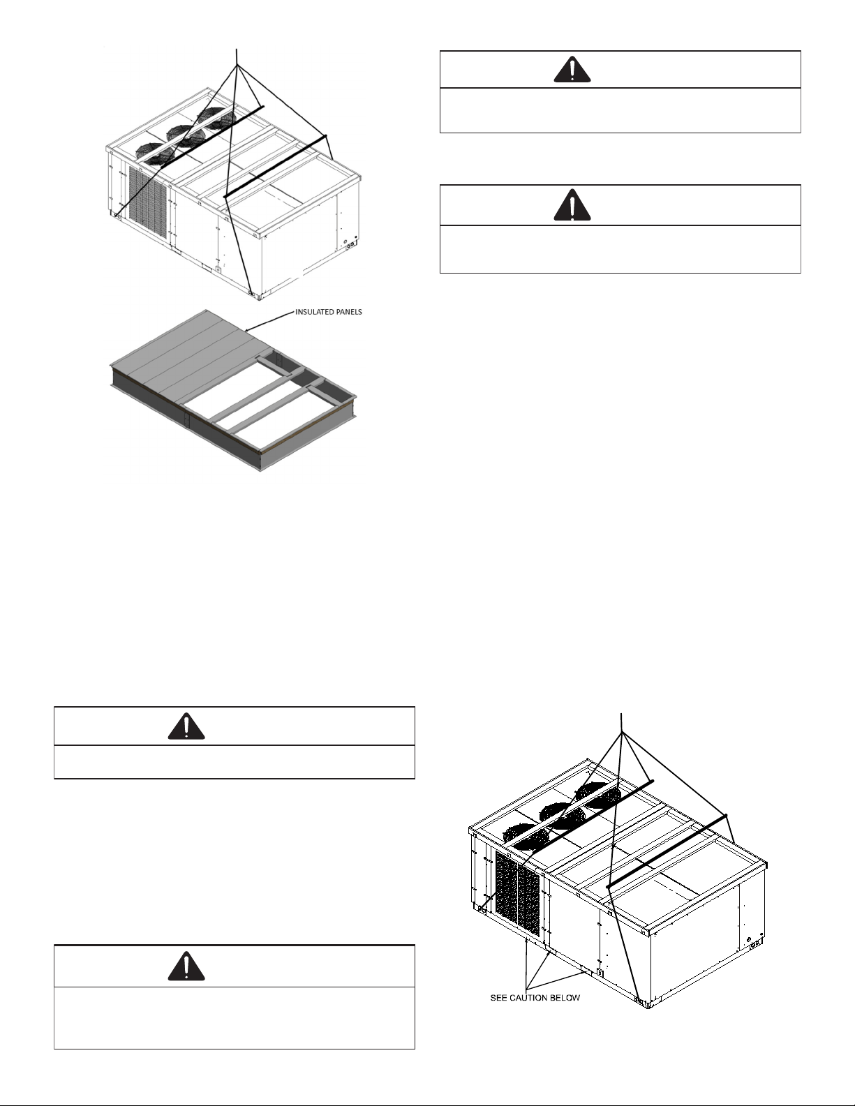
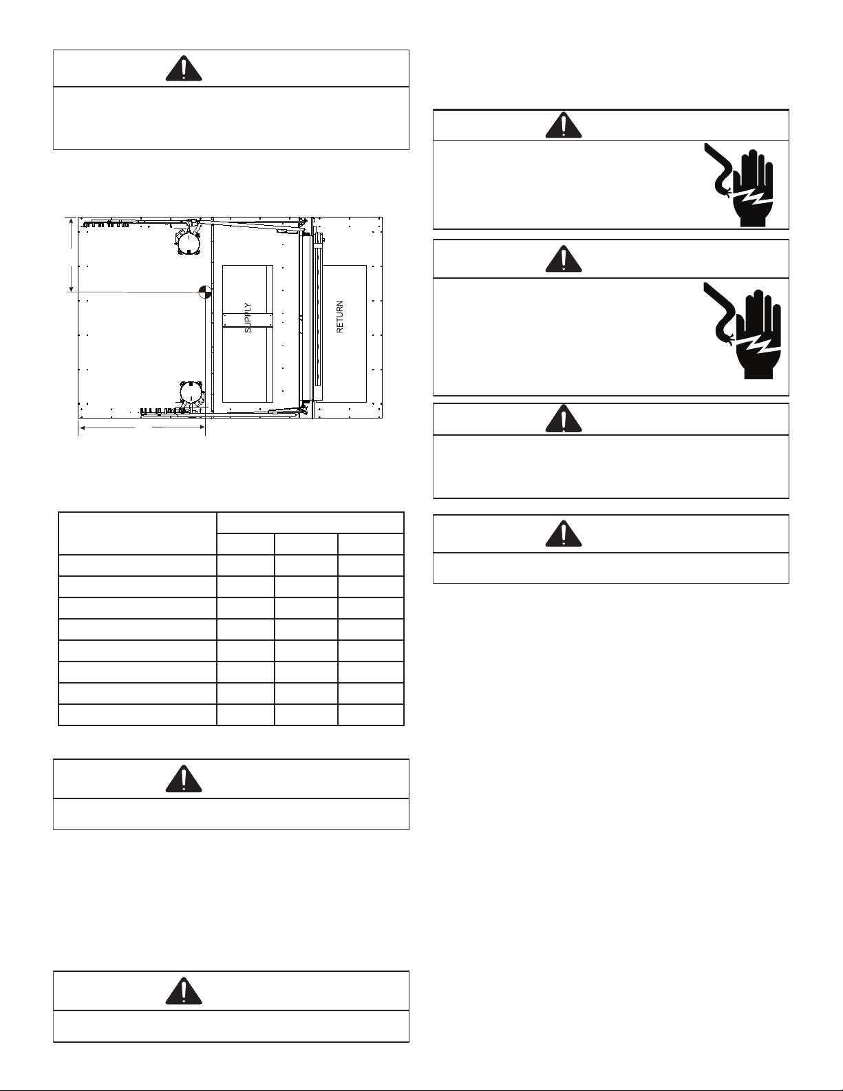
Daikin DFC Series User manual

RECOGNIZE THIS SYMBOL
AS A SAFETY PRECAUTION.
outdoor
*NOTE:
DFC SERIES
Packaged Heating and cooling Unit
15 to 25 ton
Our continuing commitment to quality products may mean a change in specications without notice.
IOD-1054A
09/2022
Index
.................................................................2
Replacement Parts ................................................................2
..............................................................2
.........................................................................4
Clearances.............................................................................6
.........................................6
....................................................6
Rigging Details.......................................................................6
Electrical Wiring ....................................................................7
.......................................................9
...............................................9
.......................................10
...........................................................11
NOTE: 25 ton model shown in picture.
20 ton model has 4 fans
15 ton model has 3 fans
INSTALLATION INSTRUCTIONS
©2022
19001 Kermier Rd. Waller, TX 77484
www.daikincomfort.com
ONLY PERSONNEL THAT HAVE BEEN TRAINED TO INSTALL,
ADJUST, SERVICE, MAINTENANCE OR REPAIR
(HEREINAFTER, “SERVICE”) THE EQUIPMENT SPECIFIED IN
THIS MANUAL SHOULD
SERVICE THE EQUIPMENT. THE MANUFACTURER WILL
NOT BE RESPONSIBLE FOR ANY INJURY OR PROPERTY
DAMAGE ARISING FROM IMPROPER SERVICE OR SERVICE
PROCEDURES. IF YOU SERVICE THIS UNIT, YOU ASSUME
RESPONSIBILITY FOR ANY INJURY OR PROPERTY
DAMAGE WHICH MAY RESULT. IN ADDITION, IN
JURISDICTIONS THAT REQUIRE ONE OR MORE LICENSES
TO SERVICE THE EQUIPMENT SPECIFIED IN THIS
MANUAL, ONLY LICENSED PERSONNEL SHOULD SERVICE
THE EQUIPMENT.
IMPROPER INSTALLATION, ADJUSTMENT, SERVICING,
MAINTENANCE OR REPAIR OF THE EQUIPMENT SPECIFIED
IN THIS MANUAL, OR ATTEMPTING TO INSTALL, ADJUST,
SERVICE OR REPAIR THE EQUIPMENT SPECIFIED IN THIS
MANUAL WITHOUT PROPER TRAINING MAY RESULT IN
PRODUCT DAMAGE, PROPERTY DAMAGE, PERSONAL
INJURY OR DEATH.
WARNING
WARNING
DO NOT BYPASS SAFETY DEVICES

2
SAFETY INSTRUCTIONS
WARNING
To avoid property damage, personal injury or death, do not
use this unit if any part has been under water. Immediately
call a qualified service technician to inspect the furnace
and to replace any part of the control system and any gas
control having been under water
CAUTION
Sheet metal parts, screws, clips and similar items inherently
have shart edges, and it is necessary that the installer and
servicer personnel exercise caution.
WARNING
Do not connect to or use any device that is not design cer-
tified by the manufacturer for use with this unit. Serious
property damage, personal injury, reduced unit performance
and/or hazardous conditions may result from the use of such
non-approved devices.
WARNING
This unit must not be used as a “construction heater” during
the finishing phases of construction on a new structure. This
type of use may result in premature failure of the unit due
to extremely low reurn air temperatures and exposure to
corrosive or very dirty atmospheres.
WARNING
HIGH VOLTAGE
DISCONNECT ALL POWER BEFORE SERVICING
OR INSTALLING THIS UNIT. MULTIPLE POWER
SOURCES MAY BE PRESENT. FAILURE TO DO SO
MAY CAUSE PROPERTY DAMAGE, PERSONAL
INJURY OR DEATH.
WARNING
To prevent the risk of property damage, personal injury or
death, do not store combustible materials or use gasoline
or other flammable liquids or vapors in the vicinity of this
appliance.
REPLACEMENT PARTS
855-DAIKIN-1
GENERAL INFORMATION
WARNING
To prevent property damage, personal injury or death due to
fire, explosions, smoke, soot, condensation, electric shock
or carbon monoxide, this unit must be properly installed,
repaired, operated and maintained.
-
............................12
Maintenance .......................................................................14
.................................17
Appendix B Electrical Data...................................................29
Appendix C Unit Dimensions ...............................................34
Appendix D Wiring Diagrams...............................................25
.................................................................47

3
-
-
-
NOTE: -
UNIT LOCATION
WARNING
To prevent possible equipment damage, property damage,
personal injury or death, the following must be observed
when installing the unit.
IMPORTANT NOTE:
See important note under Roof Curb Installaon Only.
Unit should be energized 24 hours prior to
compressor start up to ensure crankcase heater has suciently
warmed the compressors. Compressor damage may occur if
this step is not followed.
NOTE:
-

4
•
•
•
•
•
•
•
•
•
•
•
•
B
MUST BE REMOVED
Please follow the instrucons below to remove brace.
CAUTION
When unit is suspended, boards and shipping brace will
drop when screws are removed. To prevent personal injury,
STAND CLEAR. Remove fork hole brackets, boards and
shipping brace from bottom of unit before placing units
onto curb.
The struts are located in the fork holes and
are used to protect the unit from damage while liing with
forks. The shipping brace is located under the unit (under
compressor).

5
LIFT OVER APPROXIMAT E
CENTER OF UNIT
SPREADER BARS
MUST BE USE D W ITH
LIFTING STRAPS THAT
ARE LESS THAN 16
FEET L ONG
REMOVE 2 BRACKETS
ON EACH END TO
REMOVE
WOODEN STRUTS
REMOVE 2 BRACKETS
ON EACH END TO
REMOVE
SHIPPING BRACE
-
WARNING
To prevent possible equipment damage, property
damage, personal injury or death, the following
bullet points must be observed when installing
the unit.
•
•
•
NOTE:
CAUTION
All curbs look similar. To avoid incorrect curb position-
ing, check job plans carefully and verify markings on curb
assembly. Instructions may vary in curb styles and supercede
information shown.
-
CLEARANCES
*In situaons that have mulple units, a 48” minimum clearance is
required between the condenser coils.
UNIT CLEARANCES
-

6
ROOF CURB INSTALLATION
CAUTION
If protrusions exist, do not attempt to set unit on curb.
Information shown.
ROOF TOP DUCT CONNECTIONS
NOTE:
RIGGING DETAILS
WARNING
To prevent property damage, the unit should remain in an
upright position during all rigging and moving operations.
To facilitate lifting and moving when a crane is used, place
the unit in an adequate cable sling.
CAUTION
Do not lift units two at a time. Provisions for forks have
been included in the unit base fram. Minimum fork length is
72” to prevent damage to the unit.
WARNING
To prevent possible equipment damage, property damage,
personal injury or death, the following bullet points must
be observed when installing the unit.
Important:
-
DFG

7
CAUTION
When unit is suspended, boards and shipping brace will
drop when screws are removed. To prevent personal injury,
STAND CLEAR. Remove fork hole brackets, boards and
shipping brace from bottom of unit before placing units
onto curb.
COMPRESSOR 1
COMPRESSOR 2
CG
EVAPORATORCOILS
A
B
C
XD
Y
CORNER & CENTER OF GRAVITY LOCATIONS
DATA
15T 20T 25T
410 499
395
433
1993
NOTE:
CAUTION
To prevent severe damage to the bottom of the unit, do not
fork lift unit after wood struts have been removed.
CAUTION
To prevent damage to the unit, do not allow crane hooks and
spreader bars to rest on the roof of the unit.
ELECTRICAL WIRING
WARNING
HIGH VOLTAGE
DISCONNECT ALL POWER BEFORE SERVICING
OR INSTALLING THIS UNIT. MULTIPLE POWER
SOURCES MAY BE PRESENT. FAILURE TO DO SO
MAY CAUSE PROPERTY DAMAGE, PERSONAL
INJURY OR DEATH.
WARNING
HIGH VOLTAGE
TO AVOID PROPERTY DAMAGE, PERSONAL
INJURY OR DEATH DUE TO ELECTRICAL SHOCK,
DO NOT TAMPER WITH FACTORY WIRING. THE
INTERNAL POWER AND CONTROL WIRING OF
THESE UNITS ARE FACTORY-INSTALLED AND HAVE
BEEN THROUGHLY TESTED PRIOR TO SHIPMENT.
CONTACT YOUR LOCAL REPRESENTATIVE IF
ASSISTANCE IS REQUIRED.
CAUTION
To prevent damage to the wiring, protect wiring from sharp
edges. Follow national electrical code and all local codes
and ordinances. Do not route wires through removable
access panels.
CAUTION
Conduit and fittings must be weather-tight to prevent water
entry into the building.
-
-
NOTE: -
-

8
CAUTION
To avoid property damage or personal injury due to fire, use
only copper conductors.
CAUTION
To prevent improper and dangerous operation due to wiring
errors, label all wires prior to disconnection when servic-
ing controls. Verify proper operation after servicing.
NOTE:
15-25 TON TSTAT POWER AND LOW VOLTAGE
TERMINAL LOCATIONS
WARNING
Failure of unit due to operation on improper line voltage or
with excessive phase unbalance constitues product abuse and
is not covered by the warranty. It may cause severe damage to
the unit electrical components.
NOTE:
-
-

9
ELECTRICAL ENTRANCE LOCATIONS
NOTE:
NOTE:
CIRCULATING AIR AND FILTERS
CONDENSATE DRAIN CONNECTION
NOTE:
Base Rail
DRAIN CONNECTION
-

10
STARTUP, ADJUSTMENTS, AND CHECKS
WARNING
HIGH VOLTAGE
To avoid personal injury or death due to
electrical shock, bond the frame of this unit
to the building electrical ground by use of
the grounding terminal provided or other ac-
ceptable means. Disconnect all power before
servicing or installing this unit.
CAUTION
To prevent property damage or personal injury, Do not start
the unit until all necessary pre-checks and test have been
performed.
WARNING
MOVING MACHINERY HAZARD!
To prevent possible personal injury or death, disconnect
power to the unit and padlock in the “OFF” position before
servicing fans.
the
-
-
System Voltage -
Nameplate Voltage - -
-
-

11
3) PERCENT VOLTAGE
UNBALANCE
2) MAXIMUM VOLTAGE DEVIATIONS
FROM AVERAGE VOLTAGE
1) AVERAGE VOLTAGE
HOW TO USE THE FORMULA:
EXAMPLE: With voltage of 220, 216, and 213
1) Average Voltage = 220+216+213=649 / 3 = 216
2) Maximum Voltage Deviations from Average Voltage = 220 - 216 = 4
3) Percent Voltage Unbalance = 100 x = = 1.8%
Percent voltage unbalance MUST NOT exceed 2%
.
4
216
400
216
= 100 X
AIR FLOW ADJUSTMENTS
NOTE:-
Note:
-

12
DRC Model Wiring
GR (FAN)
Energized during Heat Mode
BR (Heating Stage 2)
PU (Cooling Stage 2)
WH (Heating Stage 1)
YL (Cooling Stage 1)
** TB1-DH is energized when the unit is in heat
mode. When TB1-DH is energized, the blower motor
operates at a new group of programmed speeds,
T6-T10, in place of T1-T5.
• Move YELLOW (YL) wire from TB1-T1 to T2 to change blower speed during cooling stage 1 operation.
(Do not move wires YL and PU to the same taps)
• Move WHITE (WH) wire from TB1-T6 to T7 to change blower speed during heating stage 1 operation.
(Do not move wires WH and BR to the same taps)
• Move PURPLE (PU) wire from TB1-T3 to T4 or T5 to change blower speed during cooling stage 2 operation.
(Do not move wires YL and PU to the same taps)
• Move BROWN (BR) wire from TB1-T8 to T9 or T10 to change blower speed during heating stage 2 operation.
(Do not move wires WH and BR to the same taps)
AC G Y1 Y2 W1 W2 DH T1 T2 T3 T4 T5 T6 T7 T8 T9 T10
Fan Only X GR
Cooling Mode LO X X
Cooling Mode HI X X X
Hea�ng Mode Lo X X
Hea�ng Mode HI X X X
X= 24V Signal
DFC/DFG OPERATION and WIRE RANGE CHART
DFC/DFG OPERATION
WIRE RANGE
= Range of AVAILABLE TAPS
For wire color informa�on and placement, view DFC/DFG Model Wiring

13
-
SUPERHEAT AND SUBCOOLING
SUBCOOLING FORMULA = SATURATED LIQUID LINE TEMPERA-
TURE - LIQUID LINE TEMPERATURE
SUPERHEAT = SUCTION LINE TEMP - SAT. SUCTION TEMP.
NOTE:
-
-
NOTE:
NOTE:
NOTE:

14
Design Superheat & Subcooling
Model Circuit Superheat
± 20F
Subcooling
± 10F
Expan-
sion
Device
Outdoor
Ambent
(°F)
DFG180 1 8 14 TXV 95
DFG180 2 8 12 TXV 95
DFG240 1 8 9 TXV 95
DFG240 2 8 6 TXV 95
DFG300 1 10 7 TXV 95
DFG300 2 10 7 TXV 95
-
UNIT WITH ECONOMIZER OPTION:
WARNING
BURN HAZARD!
DO NOT TOUCH! DISCHARGE LINE MAY BE HOT!
MAINTENANCE
WARNING
HIGH VOLTAGE
DISCONNECT ALL POWER BEFORE SERVICING
OR INSTALLING THIS UNIT. MULTIPLE POWER
SOURCES MAY BE PRESENT. FAILURE TO DO SO
MAY CAUSE PROPERTY DAMAGE, PERSONAL
INJURY OR DEATH.
WARNING
To prevent personal injury or death due to improper
installation, adjustment, alteration, service or maintenance,
refer to this manual. For additional assistance or
information, consult a qualified installer, service agency or
the gas supplier.
CAUTION
This unit must be ISOLATED from the gas supply piping system
by closing its individual manual shutoff valve during any
pressure testing equal to or less than 1/2 psig.
-

15
CAUTION
TO PREVENT PROPERTY DAMAGE DUE TO FIRE AND LOSS OF
EQUIPMENT EFFICIENCY OR EQUIPMENT DAMAGE DUE TO
DUST AND LINT BUILD UP ON INTERNAL PARTS, NEVER
OPERATE UNIT WITHOUT AN AIR FILTER INSTALLED IN THE
RETURN AIR SYSTEM
-
-
NOTE:
CAUTION
Prior to servicing MCHE, be sure to disconnect the power
supply and use lock-out methods to prevent the power from
accidentally being turned on.
STEP 2: Rinse
Figure 1

16
Figure 2
Figure 3
WARNING
Field applied coatings are not recommended for brazed
aluminum MicroChannel heat exchangers. MicroChannel heat
exchangers must NOT be coated using any other coating,
Coating of a coil using a supplier or coating process is not
approved and voids the product warranty. It may also reduce
the lifetime and/or the performance of the MicroChannel
heat exchanger.

17
NOTES:
422 434
503
2055
1-----
-----
509
3945
1
5124 544
4222
1
1
911
4105
1
5955 922
1-----
-----
1
-----
1
923
1
942
1
932
T9
T5
T10
DFC1803D Standard Static
T1
T2
T3
T4
504 521
4019
2911
12424
591
5453
14141
1
910
9133
912 929
1
992
9030
912
924
1 953
990
1-----
-----
1 925 911
-----
1 935 930
9133
912 929
1
992
9030
912
924
1 953
990
T9
T5
T10
DFC2403D Standard Static
T1
T2
T3
T4

18
NOTES:
594
5095
1
1
902 921
923
1 954 951
1000
1051
10323
1132
110002 1152
1132
1013
1112
10521 1140
10359
1 1120
10000 1211 1152
-----
-----
1-----
-----
913
949
1 991
-----
9934
1110 999
9559
19201
1212 1120
1123
10203 1149 1034
10034
1199
1 1222
1245
1013
1112
10521 1140
10359
1 1120
10000 1211 1152
T9
T5
T10
DFC3003D Standard Static
T1
T2
T3
T4

19
NOTES:
925
953
913
5392 944
1 1 1033
4503 1010
3515 911 1090
1122
1020 1154
2 2
1305 1109 1103 5401 1215
9129
5392 912 910
1 1 942
4503
3515 911 1022 1015
1053
1020 1109 1090
2 2 1150
1305 1109 1103
923 920
1 1 952
923 990
991 1022
5502 1033 1020 1059
5050 1059 1114
2 1122 1101 2 1155 1134
1141 1201
9405
9091
930
1 924 921 1
994
1009 1033
1051 1039
1100
2 1139 2 1159
1205
9495
901
923 920 934
1 952 1
990 1003 999
1022 1033
1059
1114 1121 1104
2 1155 1134 2 1141
1201
T9
T10
T4
T5
T3
T1
T2

20
NOTES:
9125
935 901
1 1
4519 900
4139 1029
1109
1034 1012 - - - - -
2 1043 2 - - - - -
- - - - -
9412
9124
925
920
1 1
911 1020 1024
934 1050
992 1090 1124
1039 1029 1129 1155
23510 2
3192 1099 - - - - -
9412 919
930 9153 954
925 942
1 992 1 1013 995
1025 1045 1042
1054 1095
1094 1111 1140
1133
2 2 1201
1209 1223 1229
909 909
941 941
9353 915 9353 915
959 959
19025 1032 1009 19025 1032 1009
1055 1055
1090 1090
1151 1151
2 1199 1211 2 1199 1211
1239 1239
902 902
993 935 993 935
1025 1025
1055 1055
1 1042 1 1042
9235 9235
1132 1133 1132 1133
1204 1204
2 1232 1233 2 1232 1233
1259 1259
T9
T10
T4
T5
T3
T1
T2
Other manuals for DFC Series
1
This manual suits for next models
3
Table of contents
Other Daikin Accessories manuals

Daikin
Daikin DFG Series User manual

Daikin
Daikin FWTSKA Owner's manual

Daikin
Daikin 910247450 Manual

Daikin
Daikin KRCS01-8B User manual

Daikin
Daikin 2508032 User manual

Daikin
Daikin EKRSCA1 User manual

Daikin
Daikin DPS User manual

Daikin
Daikin FWHSK User manual

Daikin
Daikin DP3G Series User manual

Daikin
Daikin AKZ8 Series User manual
Popular Accessories manuals by other brands

Keysight Technologies
Keysight Technologies N6841A user guide

Sercomm
Sercomm SD-DWS07 installation guide

Bosch
Bosch rexroth APAS CDE V01.00.00 operating instructions

Vicinoate
Vicinoate 158746.01 user manual

LuxaFlex
LuxaFlex Armony Plus Instruction manual for use and maintenance

Hotron
Hotron HR100-CT user manual