Daikin MCS341-DS1-111 How to use

Installer reference guide
Security gateway
MCS341-DS1-111

Table of contents
Installer reference guide
2
MCS341-DS1-111
Security gateway
4P529063-1A – 2020.12
Table of contents
1 About this document 3
2 Installation 4
2.1 General safety precautions............................................................................................................................................. 4
2.1.1 General ........................................................................................................................................................... 4
2.1.2 Installation site ............................................................................................................................................... 5
2.1.3 Electrical ......................................................................................................................................................... 5
2.2 Daikin system equipment ............................................................................................................................................... 6
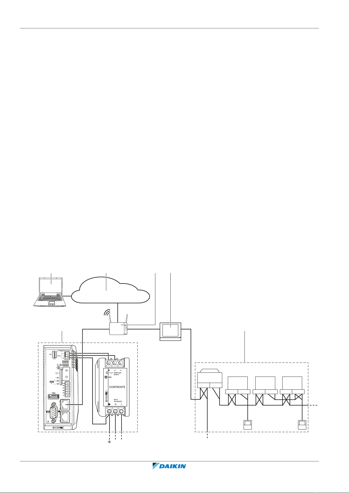
2.3 System description.......................................................................................................................................................... 6
2.3.1 Local network setup ....................................................................................................................................... 6
2.3.2 Specifications.................................................................................................................................................. 7
2.4 Before installation........................................................................................................................................................... 7
2.4.1 About necessary equipment .......................................................................................................................... 7
2.4.2 About the location of the terminals............................................................................................................... 8
2.5 To install the 2 Security gateway hardware components.............................................................................................. 8
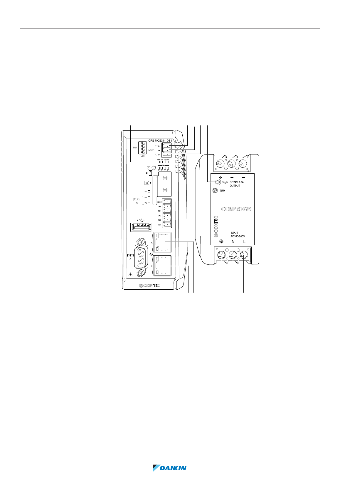
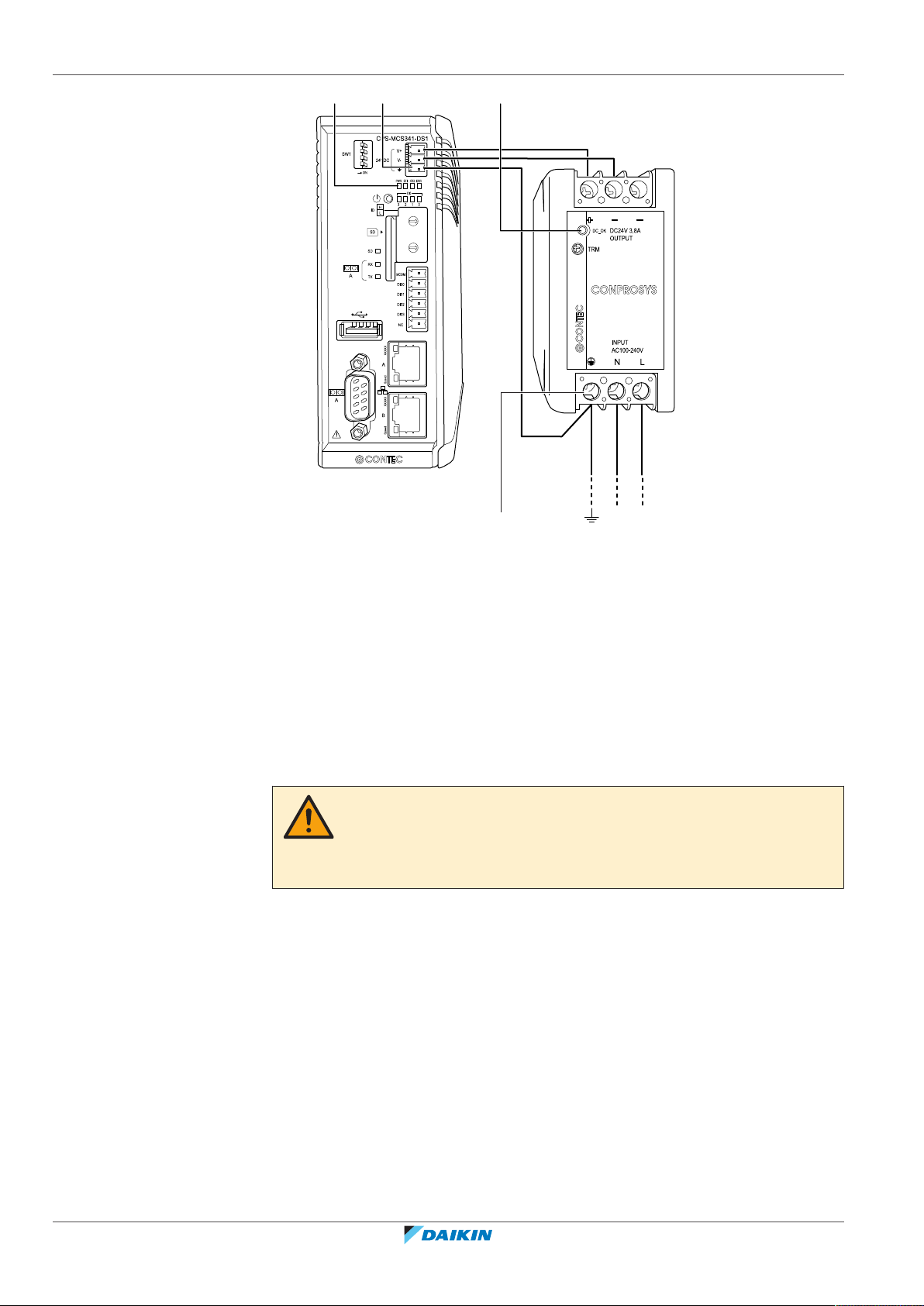
2.6 About electric wiring....................................................................................................................................................... 9
2.6.1 To connect the power supply......................................................................................................................... 9
2.6.2 To connect the Security gateway to the local network................................................................................. 10
3 Commissioning 12
3.1 About commissioning the Security gateway setup........................................................................................................ 12
3.2 Minimum requirements for the commissioning ............................................................................................................ 12
3.3 To connect to the Security gateway for the first time ................................................................................................... 13
3.4 About configuring the Security gateway ........................................................................................................................ 15
3.4.1 To access the Security gateway ..................................................................................................................... 15
3.4.2 To set up the network of the Security gateway............................................................................................. 17
3.4.3 To set up the time zone of the Security gateway .......................................................................................... 20
4 To commission the iTM or LC8 controller 21
5 Operation 23
5.1 About logs download ...................................................................................................................................................... 23
5.1.1 To download communication logs................................................................................................................. 23
5.1.2 To download update logs............................................................................................................................... 24
5.1.3 To download monitoring logs ........................................................................................................................ 26
5.2 To reset the Security gateway to its factory settings..................................................................................................... 27
5.3 To reboot the Security gateway ..................................................................................................................................... 28
5.4 To check the version numbers ....................................................................................................................................... 30
6 Troubleshooting 31
6.1 Conceivable failures........................................................................................................................................................ 31
6.2 Error messages................................................................................................................................................................ 31
7 Technical specifications 33
7.1 Commissioning computer requirements........................................................................................................................ 33
7.2 Power consumption specifications Security gateway.................................................................................................... 33
7.3 Default tool passwords ................................................................................................................................................... 33
7.4 Wiring requirements Security gateway.......................................................................................................................... 33
7.5 System requirements...................................................................................................................................................... 34
8 Appendix A – About detecting the IP address of the Security gateway 35
8.1 To wire the Security gateway ......................................................................................................................................... 35
8.2 To detect the IP address ................................................................................................................................................. 35
9 Appendix B – About commissioning in case of Proxy Server 38
9.1 Alternative setup............................................................................................................................................................. 38
9.2 To access the Security gateway...................................................................................................................................... 38
9.3 To set up the network of the Security gateway ............................................................................................................. 38
9.4 To set up the time zone of the Security gateway .......................................................................................................... 40
9.5 To commission the iTM or LC8 controller ...................................................................................................................... 41

1 | About this document
Installer reference guide
3
MCS341-DS1-111
Security gateway
4P529063-1A – 2020.12
1 About this document
Target audience
Authorised installers
Documentation set
This document is part of a documentation set. The complete set consists of:
▪Installation manual:
-Installation instructions
-Format: Paper (supplied in the kit)
▪Installer reference guide:
-Preparation of the installation, reference data,…
-Format: Digital files on http://www.daikineurope.com/support-and-manuals/
product-information/
▪Airnet handbook:
-Commissioning of the iTM or LC8 controller
-Format: Digital files on http://www.daikineurope.com/support-and-manuals/
product-information/
▪Intelligent Touch Manager installation manual (DCM601A51):
-Installation instructions
-Format: Digital files on http://www.daikineurope.com/support-and-manuals/
product-information/
▪LC8 installation manual (DLC602B51):
-Installation instructions
-Format: Digital files on http://www.daikineurope.com/support-and-manuals/
product-information/
Latest revisions of the supplied documentation may be available on the regional
Daikin website or via your dealer.
The original documentation is written in English. All other languages are
translations.
Technical engineering data
▪A subset of the latest technical data is available on the regional Daikin website
(publicly accessible).
▪The full set of latest technical data is available on the Daikin Business Portal
(authentication required).

2 | Installation
Installer reference guide
4
MCS341-DS1-111
Security gateway
4P529063-1A – 2020.12
2 Installation
2.1 General safety precautions
Please read these general safety precautions carefully before installing air
conditioning equipment, and be sure to install the equipment correctly.
Failure to follow these instructions properly may result in property damage or
personal injury, which may be serious depending on the circumstances.
After completing the installation, make sure the power supply and controller
modules operate properly during the startup operation.
Meaning of warnings and symbols
These safety messages are used to attract your attention. The meaning of each
safety message is described below:
WARNING
Indicates a situation that could result in death or serious injury.
CAUTION
Indicates a situation that could result in minor or moderate injury.
DANGER
Indicates a situation that results in death or serious injury.
DANGER: RISK OF EXPLOSION
Indicates a situation that could result in explosion.
INFORMATION
Indicates useful tips or additional information.
NOTICE
Indicates a situation that could result in equipment or property damage.
2.1.1 General
If you are NOT sure how to install or operate the unit, contact your dealer.
WARNING
Improper installation or attachment of equipment or accessories could result in
electrical shock, short-circuit, leaks, fire or other damage to the equipment. Only use
accessories, optional equipment and spare parts made or approved by Daikin.
WARNING
Make sure installation, testing and applied materials comply with applicable
legislation (on top of the instructions described in the Daikin documentation).

2 | Installation
Installer reference guide
5
MCS341-DS1-111
Security gateway
4P529063-1A – 2020.12
CAUTION
Wear adequate personal protective equipment (protective gloves, safety glasses,…)
when installing, maintaining or servicing the system.
WARNING
Tear apart and throw away plastic packaging bags so that nobody, especially
children, can play with them. Possible risk: suffocation.
2.1.2 Installation site
Do NOT install the equipment in a potentially explosive atmosphere.
2.1.3 Electrical
DANGER: RISK OF ELECTROCUTION
▪Turn OFF all power supply before connecting electrical wiring or touching
electrical parts.
▪Disconnect the power supply for more than 10minutes, and measure the voltage
at the terminals of main circuit capacitors or electrical components before
servicing. The voltage MUST be less than 50VDC before you can touch electrical
components. For the location of the terminals, see the wiring diagram.
▪Do NOT touch electrical components with wet hands.
▪Do NOT leave the unit unattended when the service cover is removed.
WARNING
A main switch or other means for disconnection, having a contact separation in all
poles providing full disconnection under overvoltage categoryIII condition, shall be
installed in the fixed wiring.
WARNING
▪ONLY use copper wires.
▪Make sure the field wiring complies with the applicable legislation.
▪All field wiring must be performed in accordance with the wiring diagram
supplied with the product.
▪Make sure to install earth wiring. Do NOT earth the unit to a utility pipe, surge
absorber, or telephone earth. Incomplete earth may cause electrical shock.
▪Make sure to use a dedicated power circuit. NEVER use a power supply shared by
another appliance.
▪Make sure to install the required fuses or circuit breakers.
▪Make sure to install an earth leakage protector. Failure to do so may cause
electric shock or fire.
WARNING
▪After finishing the electrical work, confirm that each electrical component and
terminal inside the electrical components box is connected securely.
▪Make sure all covers are closed before starting up the unit.

2 | Installation
Installer reference guide
6
MCS341-DS1-111
Security gateway
4P529063-1A – 2020.12
2.2 Daikin system equipment
The installation requires:
-The gateway MCS341-DS1-111, spare part number EU.SB.5000072. The wiring
to connect to the power convertor is included here.
-An AC/DC power convertor (PWD-90AW24), spare part number 999175A.
And one of the following:
-iTM controller, product number DCM601A51
-LC8 controller, product number DLC602B51
For more information on this equipment, see "4 To commission the iTM or LC8
controller"[421].
If there is a missing or defective part, contact the dealer where you purchased this
product.
2.3 System description
The Security gateway allows the iTM and LC8 to connect through the Security
gateway to the Daikin Cloud Service.
Now, instead of sending the report to the router directly, the iTM or LC8 controller
sends the report to the Security gateway first. The Security gateway transforms the
report format from http to https and then sends the transformed https report to
the Daikin Cloud Service via the router.
2.3.1 Local network setup
Set up the local network as shown in the following diagram:
F1, F2 P1, P2 F1, F2 P1, P2 F1, F2 P1, P2
F1, F2
OUT IN
F1, F2
http://cloud.daikineurope.com
RJ-45
230 V AC
f e
24 V DC
c
b
d
a

2 | Installation
Installer reference guide
7
MCS341-DS1-111
Security gateway
4P529063-1A – 2020.12
aSecurity gateway
biTM or LC8
cUnits
dLAN gateway
eDaikin Cloud Service
fComputer with connection to the Daikin Cloud Service
The table is only intended as an example and only applicable for the setup
indicated in the image above.
iTM or LC8 Security gateway Router
IP Address 192.168.1.50 192.168.1.51 192.168.1.1
SubnetMask 255.255.255.0 255.255.255.0 255.255.255.0
Default gateway 192.168.1.51 192.168.1.1
Preferred DNS 192.168.1.51 192.168.1.254
Alternate DNS 192.168.1.51 192.168.1.254
2.3.2 Specifications
Category Class Specifications Remarks
Hardware Manufacturer CONTEC —
Model number MCS341-DS1-111 —
CPU ARM Cortex-A8 600MHz —
LAN port 10BASE-T/100BASE-TX —
RAM 512MB —
ROM 32MB —
OS Ubuntu 14.04 —
Temperature
range
–20°C~+60°C —
SD card capacity 4GB —
Boot disc SD card —
2.4 Before installation
Before you start installing the Security gateway, complete the following
preparations:
▪check that the Security gateway module and power supply come with all
accessories,
▪check that you have all equipment necessary to install the Security gateway
modules, see "About necessary equipment"[47],
▪familiarize yourself with the location of the terminals and switches of the Security
gateway modules, see "About the location of the terminals"[48].
2.4.1 About necessary equipment
Use the following equipment to install Security gateway modules:
▪a flat-blade screwdriver,

2 | Installation
Installer reference guide
8
MCS341-DS1-111
Security gateway
4P529063-1A – 2020.12
▪a Phillips screwdriver,
▪the necessary amount of electrical wires and appropriate wiring tools.
For more information on what wires to use, see "2.6About electric wiring"[49].
2.4.2 About the location of the terminals
Understand the arrangement of terminals and the location of openings on the
module and plan how to route the cable and in which order to connect its wires to
facilitate the installation procedure.
For connection details see "2.6About electric wiring"[49].
jic b a
ed
h
g
f
lk
aLive terminal 230V AC
bNeutral terminal 230V AC
cEarth terminal
dPower supply output 24V DC (+)
ePower supply output 24V DC (–)
fContact input 24V DC (+)
gContact input 24V DC (–)
hEarth terminal
iEthernet connection (A) Refer to Setup types in "8 Appendix A – About detecting
the IP address of the Security gateway"[435] For correct wiring
JEthernet connection (B) Refer to Setup types in "8 Appendix A – About detecting
the IP address of the Security gateway"[435] For correct wiring
k"DC_OK" LED (DC_OK)
l"PWR" LED (PWR)
2.5 To install the 2 Security gateway hardware components
The Security gateway modules are to be mounted onto a 35 mm DIN rail.
1Place the module over the top of the DIN-35 rail so that the upper hook on the
rear face is hooked in.
2Push the module in direction (a) until the lower hook snaps into the rail.

2 | Installation
Installer reference guide
9
MCS341-DS1-111
Security gateway
4P529063-1A – 2020.12
3If necessary, pull the lever on the lower parts of the module in direction (b) to
click the module onto the rail. Use a flat-blade screwdriver if necessary.
4Repeat the previous steps for all other modules.
ba
2.6 About electric wiring
This chapter will describe the procedure to connect the Security gateway
components with Daikin devices and other equipment.
For all wiring requirements see "7.4 Wiring requirements Security
gateway"[433].
WARNING
▪Do NOT turn on the power supply before all wire connections are completed. Not
doing so may cause an electric shock.
▪After the wiring is completed, double-check that all wires are connected correctly
before turning on the power supply.
▪All field supplied parts, materials and electric works MUST comply with the
applicable legislation.
INFORMATION
At the time of writing, some connectors are NOT active, but provided for future use.
2.6.1 To connect the power supply
Connect the power supply as shown in the following arrangement:

2 | Installation
Installer reference guide
10
MCS341-DS1-111
Security gateway
4P529063-1A – 2020.12
230 V AC
24 V DC
a
c
d b
1Connect the power supply to the 3 terminals, L (live), N (neutral) and ground
in the input section of the power supply (PS).
Using the wiring delivered with the Security gateway:
2Connect the DC power supply output terminals of the PS to the contact input
terminals of the Security gateway module. Take the polarity of the wires into
account.
3Connect the earth terminal of the PS (a) to the earth terminal of the Security
gateway (b).
Once all wiring has been completed:
4Double-check and then turn on the power supply.
CAUTION
The power supply is ONLY guaranteed when the "DC_OK" LED (DC_OK)(c) on the PS
and the "PWR" LED (PWR) (d) on the Security gateway module are green.
If one or more of the above LEDs are NOT lighting up, check for faulty wiring.
2.6.2 To connect the Security gateway to the local network
Basic setup (recommended)
1Connect the power supply in the same way as shown in "To connect the
power supply"[49].
2Add the Security gateway to the local network as shown in the following
figure:

2 | Installation
Installer reference guide
11
MCS341-DS1-111
Security gateway
4P529063-1A – 2020.12
F1, F2
OUT IN
F1, F2
e
f
cb
a
d
g
h
Only LAN port A will be used in this case.
aOutdoor unit
bLAN connection (DIII)
ciTM or LC8 controller
dLAN connection to port A
eSecurity gateway
fLAN gateway (RJ-45)
gUser PC
hDaikin Cloud Service
Plug in the power supply.
To connect to DIII-NET compatible equipment
Refer to:
▪Ainet handbook:
-For commissioning of the iTM or LC8 controller
-Format: Digital files on http://www.daikineurope.com/support-and-manuals/
product-information/
▪iTM installation manual
▪LC8 installation manual
To connect the LAN cable
For all wiring requirements see "2.3System description"[46].
Do NOT connect the LAN cable until you start commissioning the LAN Gateway.
Otherwise, a network address conflict may occur.

3 | Commissioning
Installer reference guide
12
MCS341-DS1-111
Security gateway
4P529063-1A – 2020.12
3 Commissioning
WARNING
Only qualified persons should conduct commissioning.
CAUTION
Preliminary electrical system checks such as earth continuity, polarity, resistance to
earth and short circuit must be carried out by using a suitable test meter by a
competent person.
3.1 About commissioning the Security gateway setup
After you have verified that the Security gateway components have been installed
and all necessary wiring has been completed, you can start the commissioning of
your Security gateway setup.
In this commissioning phase, you will do the following:
▪Configure your computer to be able to connect to the Security gateway, see
chapter "To connect to the intelligent Tablet Controller for the first time" in the
intelligent Tablet Controller Installer reference guide.
▪Configure the LAN settings, see "3.3To connect to the Security gateway for the
first time"[413] To configure the network settings (local commissioning tool).
▪Configure the date and time, see "To set up the time zone of the Security
gateway"[420].
▪Add all attached (Daikin) equipment to the Security gateway web interface, see
"4To commission the iTM or LC8 controller"[421] to configure the connected
devices quickly (local commissioning tool).
3.2 Minimum requirements for the commissioning
Before you start configuring the Security gateway, complete the following
preparations.
▪Make sure your computer specs comply with the minimal requirements
mentioned in "7.5System requirements"[434].
▪Contact your network administrator for the following network information for
the Security gateway:
-the desired network name for the Security gateway,
-the static IP address and corresponding subnet mask of the Security gateway,
-the static IP address and corresponding subnet mask of the iTM or LC8
controller,
-the IP address of the default gateway,
-the IP address of the DNS server, and
-the IP address of the alternate DNS (if applicable).
▪Make sure the power of all connected equipment is turned on.

3 | Commissioning
Installer reference guide
13
MCS341-DS1-111
Security gateway
4P529063-1A – 2020.12
3.3 To connect to the Security gateway for the first time
A new Security gateway module has a fixed IP address 192.168.0.126 and a subnet
mask 255.255.255.0.
To connect to this device, you will have to change the IP address of your computer
to the same range as this IP address.
a b
1Plug a CAT 5e (or higher) Ethernet cable into the Security gateway module (a).
2Connect the Ethernet cable with your computer (b) and change your IP
address to match that of the Security gateway module.
3On your computer, go to the Control Panel.
4In the Control Panel, click the Network and Sharing Center option and then
the Change Adapter Settings option.
5In the Network Connections window, double-click the Local Area Connection
option.
Result: The following window appears.
6Select the Internet Protocol Version 4 (TCP/IPv4) option and click the
Properties button.
Result: The following window appears.

3 | Commissioning
Installer reference guide
14
MCS341-DS1-111
Security gateway
4P529063-1A – 2020.12
7Click the Use the Following IP Address: radio button.
8Set the following IP address (IP address): "192.168.0.2".
INFORMATION
This example uses 192.168.0.2, but you can choose any address in the range of
192.168.0.2~192.168.0.254 (except . 192.168.0.126).
9Set the following Subnet mask (Subnet mask): "255.255.255.0".
10 Click the OK (OK) button.
To prevent interference from any wireless network, disable all wireless network
cards on your computer as follows:
11 In the Network Connections window, right-click the Wireless Network
Connection option.
12 Select the Disable option.
13 Check if you can make a connection from your computer to the Security
gateway module. To do so, open the command prompt on your computer as
follows:
14 Click the Windows Start button.

3 | Commissioning
Installer reference guide
15
MCS341-DS1-111
Security gateway
4P529063-1A – 2020.12
15 In the Search box, type "Command Prompt", or alternatively "Cmd".
16 In the list of results, click the Command Prompt or Cmd option respectively.
17 Ping to the IP address of the Security gateway module. To do so, enter: "ping
192.168.0.126" and confirm by pressing the Enter key.
Result: You will receive an answer as the example below:
INFORMATION
If you do NOT get replies, but time-outs instead, there might be something wrong
with the connection. Refer to "6Troubleshooting"[431] to fix the problem.
3.4 About configuring the Security gateway
3.4.1 To access the Security gateway
See "8 Appendix A – About detecting the IP address of the Security
gateway"[435] for how to detect the IP address of the Security gateway in case
you forgot it.
1Type the default IP address of the Security gateway (https://192.168.0.126) in
the URL bar of the web browser (Google Chrome or Microsoft Edge).
Result: A warning message about the connection appears.
2Click ADVANCED (ADVANCED) to show the advanced setup window.

3 | Commissioning
Installer reference guide
16
MCS341-DS1-111
Security gateway
4P529063-1A – 2020.12
3Click Proceed to 192.168.0.126 (unsafe) (Proceed to 192.168.0.126 (unsafe)).
Result: A login window appears
4Fill out ID (ID) and Password (Password) (default ID: Daikin / default password:
Daikin) of the Security gateway and click the Sign in (Sign in ) button.

3 | Commissioning
Installer reference guide
17
MCS341-DS1-111
Security gateway
4P529063-1A – 2020.12
Result: The Security GW Menu (Security GW Menu) window appears.
3.4.2 To set up the network of the Security gateway
To access the Security GW Menu (Security GW Menu), see "To access the Security
gateway"[415].
1Click the Network (Network) button.
Result: The Network Setup (Network Setup) dialog appears.

3 | Commissioning
Installer reference guide
18
MCS341-DS1-111
Security gateway
4P529063-1A – 2020.12
2Fill out the following network data:
LAN Port1 (LAN Port1 ) (=A)
▪IP Address (IP address): Unique IP (default: 192.168.0.126) address in local
network
▪Subnet Mask (Subnet mask): 255.255.255.0
▪Default Gateway (Default Gateway): IP address (default: 192.168.0.100) of local
router
▪Primary DNS (Primary DNS): IP address (default: 192.168.0.100) of local router
▪Secondary DNS (Secondary DNS): leave blank
LAN Port2 (LAN Port2) (=B)
▪Leave empty
INFORMATION
If the IP address (IP address), default gateway (Default gateway) and primary DNS
(Primary DNS) are according to the conditions of the local network, you do not need
to change them.
3Click the Save (Save) button.
Result: The Confirm (Confirm) dialog appears.
4Click the Yes (Yes) button to reboot the Security gateway.

3 | Commissioning
Installer reference guide
19
MCS341-DS1-111
Security gateway
4P529063-1A – 2020.12
Result: This will reboot the Security gateway.
Result: The web browser window appears.
Result: The IP address will be changed.
INFORMATION
The web browser communication will be lost once step 4 is executed. Follow the
procedure as described in "To access the Security gateway" [4 15] to reconnect by
using the new IP address.
5Reset the LAN network settings of your computer to their original values.
6If you disabled it before, enable the WiFi adapter of your computer.
7Disconnect the Ethernet cable between your computer and the Security
gateway module.
8Connect an Ethernet cable between the Security gateway module and the
local network.
F1, F2
OUT IN
F1, F2
e
f
cb
a
d
g
h
INFORMATION
For confirmation that the IP address is changed correctly, access the Security
gateway as described in "To access the Security gateway"[415] by using the new IP
address.

3 | Commissioning
Installer reference guide
20
MCS341-DS1-111
Security gateway
4P529063-1A – 2020.12
3.4.3 To set up the time zone of the Security gateway
To access the Security GW Menu (Security GW Menu), see "To access the Security
gateway"[415].
1Click the Time Zone (Time Zone) button.
Result: The Time Zone Setup (Time Zone Setup) dialog appears.
2Click the [▼] button to open Time Zone drop-down list >> select and click the
time zone.
3Click the Save (Save) button.
Table of contents
Other Daikin Gateway manuals

Daikin
Daikin intelligent Touch Manager BACnet DCM014A51 Guide

Daikin
Daikin EKBMSMBA User manual

Daikin
Daikin intelligent Touch Manager BACnet DCM014A51 Instruction manual

Daikin
Daikin DIII-NET User manual

Daikin
Daikin Rotex RoCon G1 User manual

Daikin
Daikin intelligent Touch Manager BACnet DCM014A51 Guide

Daikin
Daikin BAG User manual