Daikin LXE10E -A33 User manual

TR06-04
Marine type Container Refrigeration Unit
LXE10E-A33
Service Manual ·Parts List
Optional Functions
https://daikin-p.ru

11
Covered Models
Regarding the features and operation of the unit, this service manual
describes the items which are different from those of the service manual
TR01-09A.
For the ☆marked items, refer to the details in the following pages.
NO. Item Different points from service manual
(Maintenance and Repair)
1☆Dehumidification function Refer to the details in the following pages.
2☆Setting temperature range Refer to the details in the following pages.
https://daikin-p.ru

2
*Differences from standard model service manual (TR01-09A) are marked with ☆
CONTENTS
3.10 Chartless function..................................... 3-56
3.10.1 Chart indication function .................... 3-56
3.10.2 P code (Pull down time indication)..... 3-58
3.10.3 Chartless code display function ......... 3-59
3.10.3.1 List of chartless code .................. 3-59
3.10.3.2 H-code ........................................ 3-60
3.10.3.3 d-code:........................................ 3-62
3.11 Communication modem............................ 3-63
4. Service and Maintenance................................. 4-1
4.1 Maintenance service .................................... 4-1
4.1.1 Collection of refrigerant.......................... 4-1
4.1.2 Gauge manifold ..................................... 4-1
4.1.3 Automatic pump down ........................... 4-3
4.1.4 Refrigerant recovery and charge ........... 4-5
4.2 Main components and maintenance............. 4-9
4.2.1 Scroll compressor .................................. 4-9
4.2.2 Fan and fan motor................................ 4-11
4.2.3 PT and CT board (EC9756)................. 4-12
4.2.4 Electronic expansion valve .................. 4-14
4.2.5 Suction modulation valve ..................... 4-15
4.2.6 Drier ..................................................... 4-16
4.2.7 Solenoid valve...................................... 4-17
4.2.8 Discharge pressure regulating valve.... 4-18
4.2.9 Check valve ......................................... 4-18
4.2.10 High-pressure switch (HPS) .............. 4-19
4.2.11 Low pressure transducer (LPT) ......... 4-19
4.2.12 High pressure transducer (HPT)........ 4-20
4.2.13
Air-cooled condenser and evaporator
... 4-20
4.2.14 Fusible plug ....................................... 4-21
4.2.15 Liquid/moisture indicator.................... 4-21
4.2.16 Evacuation and dehydrating .............. 4-22
5. Optional Devices............................................... 5-1
5.1 Electronic temperature recorder ................... 5-1
5.2 USDA transportation..................................... 5-3
5.2.1 Type of USDA sensor/receptacle ........... 5-3
5.2.2 Initial setting........................................... 5-3
5.2.3 USDA sensor calibration........................ 5-3
5.2.4 USDA transportation requirement.......... 5-3
5.2.5 USDA report .......................................... 5-3
5.3 TransFRESH................................................. 5-5
6. Troubleshooting ................................................ 6-1
6.1
Refrigeration system and electrical system
... 6-1
6.2 Alarm codes on electronic controller ............ 6-4
6.3
Troubleshooting for automatic PTI (J-code)
... 6-9
6.4 Diagnosis based on the recording chart..... 6-11
6.5 Emergency operation ................................. 6-14
6.5.1 Emergency operation of controller....... 6-14
6.5.2 Short circuit operation of controller...... 6-15
6.5.3
Opening adjustment of electronic expansion valve
... 6-16
6.5.4
Opening adjustment of suction modulation valve:
... 6-17
6.5.5 Automatic Back up for supply/ return air
temperature sensors............................ 6-18
6.6
Troubleshooting for automatic PTI (J-code)
... 6-19
7. Appendix ........................................................... 7-1
7.1 Standard tightening torques for bolts............ 7-1
7.2 Standard tightening torque for flare nut ........ 7-1
7.3
Resistance of motor coil and solenoid valve coil
... 7-1
7.4
HFC134a, temperature-vapor pressure characteristics table
... 7-2
7.5
Temperature conversion table and temperature sensor
(SS/RS/DSS/DRS/RSS/RRS/EIS/EOS/SGS/AMBS)
characteristics table
............................................ 7-3
7.6
Temperature conversion table and temperature
sensor (DCHS) characteristics table
............... 7-4
7.7
High pressure transducer characteristics table
... 7-4
7.8
Low pressure transducer characteristics table
... 7-4
7.9 Piping diagram.............................................. 7-5
7.10 Pilot lamps and monitoring circuit............... 7-6
7.11 Fuse protection table .................................. 7-7
7.12 Schematic wiring diagram .......................... 7-9
7.13 Stereoscopic wiring diagram .................... 7-10
Safety Precautions
• Danger ................................................................ 3
• Warning ............................................................... 4
• Caution................................................................ 5
1. Introduction....................................................... 1-1
1.1 Operation range............................................ 1-1
1.2 Basic Names of components........................ 1-1
1.3 Basic operation of refrigeration unit.............. 1-2
1.3.1 Starting operation .................................. 1-2
1.3.2 Checking during operation..................... 1-3
1.3.3 Procedure after operation ...................... 1-3
1.3.4 Adjust the ventilation.............................. 1-4
2. General description .......................................... 2-1
2.1 Main specifications ....................................... 2-1
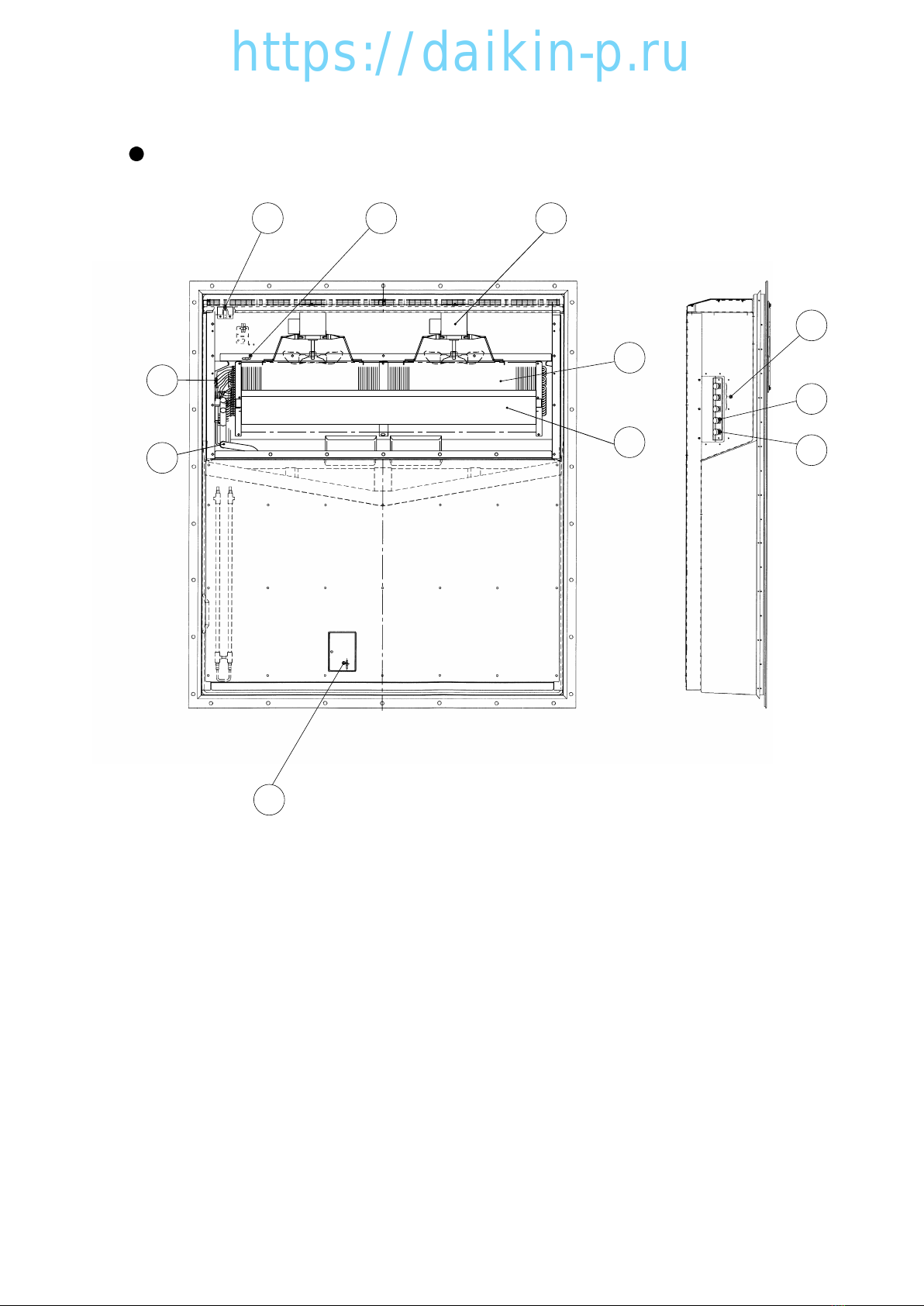
2.2 Names of components.................................. 2-2
2.2.1 Outside .................................................. 2-2
2.2.2 Inside ..................................................... 2-4
2.2.3 Control box ............................................ 2-6
2.3
Set point of functional parts and protection devices
... 2-9
2.4 Operating pressure and running current..... 2-10
2.5 Operation modes and control ..................... 2-14
2.5.1 Frozen mode........................................ 2-15
2.5.2 Chilled and partial frozen mode........... 2-17
2.5.3 Defrosting mode .................................. 2-19
2.5.4 Dehumidification mode (Optional) ....... 2-22
2.5.5 Common control .................................. 2-23
3. Electronic Controller ........................................ 3-1
3.1 Function table ............................................... 3-1
3.2 Basic operation of electronic controller......... 3-3
3.2.1 Control panel ......................................... 3-3
3.2.2 Operation mode and control .................. 3-5
3.3 Operation procedure..................................... 3-6
3.3.1 Operation procedure flow chart ............. 3-6
3.3.2 Mode operation procedure..................... 3-9
1.
Current (Operation state) indication mode
... 3-9
2. Operation setting mode........................ 3-10
3. Battery mode ....................................... 3-11
4. Mode operation .................................... 3-12
5. LED display light-OFF mode................ 3-14
6. Sensor indication mode ....................... 3-15
7. Temperature record scroll mode .......... 3-18
8. Alarm record scroll mode ..................... 3-21
9. PTI record scroll mode......................... 3-23
3.3.3 Setting flow chart ................................. 3-24
10. Optional function setting mode .......... 3-26
11. Basic function setting mode ............... 3-27
12. Optional condition setting mode......... 3-29
13. Input data mode ................................. 3-31
14. Controller software download mode... 3-32
3.4 Alarm display and back-up function............ 3-33
3.4.1 Alarm list .............................................. 3-33
3.4.2
Back-up operation at sensor malfunction
... 3-34
3.5 Battery ........................................................ 3-36
3.5.1 Specifications....................................... 3-36
3.5.2 Function ............................................... 3-36
3.6
Information interchange with personal computer
... 3-37
3.6.1 Data logging......................................... 3-38
3.6.2 Software configuration ......................... 3-39
3.7
Inspection procedure for the electronic controller
... 3-41
3.8
Controller replacement and the initial setting
... 3-42
3.8.1 Controller replacement ........................ 3-42
3.8.2 Initial setting & operation procedure .... 3-43
3.8.3
Initial setting table into spare controller
... 3-44
3.9
PTI (Pre-Trip Inspection) and periodic inspection
... 3-45
3.9.1 Inspection item..................................... 3-46
3.9.2 Automatic PTI (Pre-Trip Inspection)..... 3-49
3.9.2.1 PTI selection mode ....................... 3-50
3.9.2.2 Short PTI (S.PTI) .......................... 3-51
3.9.2.3 Full PTI (F.PTI).............................. 3-52
3.9.2.4
Alarm list during PTI (Pre-Trip Inspection)
... 3-53
3.9.2.5 Manual check (M.CHECK)............ 3-54
☆
☆
☆
☆
☆
☆
☆
☆
☆
☆
https://daikin-p.ru

31-1
1. Introduction
1.1 OPERATION RANGE
Use the units within the following range.
1.2 BASIC NAMES OF COMPONENTS
Ambient temperature range
Inside temperature range
Voltage
Vibration and shock
Operation range
-30˚C to +50˚C (-22˚F to + 122˚F)
-30˚C to +30˚C (-22˚F to + 86˚F)
50Hz: 380V/400V/415V, 60Hz: 440V/460V
Voltage fluctuation rate should be within ±10%
2G
Item
112
13
6
10
4
11
5
9
8
2
3
7
qCompressor
wAir-cooled condenser
eReceiver
rEvaporator
tControl box
Outside: switch, manual defrost switch
Inside: circuit breaker
yCondenser fan
uDrier
iAccess panel
oStorage space for power cable
!0 Ventilator
!1 Sampling port (Return) Use this port to measure the
inside return air temperature.
!2 Gas sampling port This is used to measure the
Sampling port (Supply) inside supply air temperature
and inside CO2concentration.
!3 Liquid moisture indicator
https://daikin-p.ru

4 2-1
2. General description
2.1 Main specifications
Model
Item LXE10E
Condenser cooling system Air cooled type
Controller DECOS3d
Power supply AC 3-phase 380V/400V/415V 50Hz, 440V/460V 60Hz
Compressor Hermetic scroll type (Motor output: 5.5kW)
Evaporator Cross fin coil type
Air-cooled condenser Cross fin coil type
Evaporator fan Propeller fan
Evaporator fan motor Three-phase squirrel-cage induction motor
Condenser fan Propeller fan
Condenser fan motor Three-phase squirrel-cage induction motor
Defrosting
Hot-gas defrosting system
Dual timer, on-demand defrost and manual switch
Detecting the temperature of evaporator outlet pipe and return air
Electronic expansion valve
Capacity control
Capacity control with hot gas bypass and suction modulating valve
Protective devices
/Safety devices
Circuit breaker, PT/CT board (for over current protection).
Condenser fan-motor thermal protector
Evaporator fan-motor thermal protector
High-pressure switch, Fusible plug, Fuse (10A, 5A)
Refrigerant (charged amount) R134a : 4.6 (kgf)
Refrigerant oil (charged amount) IDEMITSU, Daphne hermetic oil FVC 46D : 2.2(R)
Weight 465 (kgf)
System
Initiation
Termination
Refrigerant flow control
Compressor thermal protector
https://daikin-p.ru

52-2
2.2 Names of components
2.2.1 Outside
LXE10E
qAccess panel
wThermometer check port (Return air)
eCondenser fan motor (CFM)
rHot-gas solenoid valve (HSV)
tDefrost solenoid valve (DSV)
yDischarge gas by-pass solenoid valve (BSV)
uElectronic expansion valve (EV)
iEconomizer solenoid valve (ESV)
oInjection solenoid valve (ISV)
!0 Air-cooled condenser
!1 Liquid/moisture indicator
!2 Liquid receiver
!3 Drier
!4 Liquid solenoid valve (LSV)
!5 Suction modulating valve (SMV)
!6
Discharge pressure regulating valve (DPR)
!7 Compressor suction pipe temperature
sensor (SGS)
!8 Ambient temperature sensor (AMBS)
!9 Thermometer check port (Supply air)
@0 Compressor (MC)
@1 Discharge pipe temperature sensor
(DCHS)
@2 Storage space for power cable
@3 Low pressure transducer (LPT)
@4 High pressure transducer (HPT)
@5 High pressure switch (HPS)
@6 Control box
@7 Ventilator
@8 Reheat coil solenoid valve (RSV)
21 20 19 1817
11
27
3
24
2
26
22
1
10
14
12
25
13
23
16 15
7
5
9
8
6
4
28
https://daikin-p.ru

6 2-4
2.2.2 Inside
LXE10E
qEvaporator fan motor (EFM)
wEvaporator
eSupply air temperature sensor (SS)
Data recorder supply air temperature sensor (DSS)
rEvaporator outlet pipe temperature sensor (EOS)
tEvaporator inlet pipe temperature sensor (EIS)
yReturn air temperature sensor (RS)
Data recorder return air temperature sensor (DRS)
uUSDA receptacle
iCargo temp. receptacles
oP.C. Port receptacles
!0 Humidity sensor
!1 Reheat coil
10 6
5
4
1
2
11
7
8
9
3
https://daikin-p.ru

72-6
2.2.3 Control box
qController operation panel (EC3, 4)
wMANUAL DEFROST key
eUNIT ON/OFF key
rPhase correction contactor (PCC1,2)
tMagnetic contactor for high speed evaporator fan (EFH)
yMagnetic contactor for low speed evaporator fan (EFL)
uMagnetic contactor condenser fan (CFC)
iReverse phase protection device (RPP)
oAdopter PCB (EC6)
!0 Terminal block board (TB1)
!1 Controller CPU / IO board (EC1, 2)
!2 Fuse (Fu1-6)
!3 Rechargeable battery (BAT)
!4 Voltage indicator
!5 Personal computer receptacle
!6 Circuit breaker (CB)
!7 PT/CT board
!8 Transformer (TrC), control circuit
!9 Magnetic contactor for compressor (CC)
@0 P.C.B for humidity sensor (HUS)
@1 Modem (RCD)
@2 Noise filter (NF)
Operation panel
(Outside of the control box)
Controller
Inside of the control box
2
3
1
3
1
2
b
–12 –10 –8–6 –4 –2
–2–3–4–5–6 –1
SP–5
OVER
2
INRANGE
HOURS
DAYS
1
UNDER
ALARM
R.H.
SUPPLY
RETURN
˚C / ˚F
%R H
DEFROST INRANGED–HUMID
COMP.
˚C
˚C
SP+
5
DECOS
DAIKIN ELECTRONICCONTAINER OPERATION SYSTEM
20
13
15
PAK-61JC
10
9
22
21
1114
4
17
5
11
16
8
PAK-61JC
19
PAK-61JC
12
7
18
B4P–VH B4P–VH
FUSE
6
B3PSVH
RA–H341TD
B5P-VH
35J
PAK-
https://daikin-p.ru

Device name Actuation Set point Detection method Symbol
High-pressure switch OFF 2400kPa (24.47kg/cm2) High-pressure switch HPS
ON 1900kPa (19.37kg/cm2)
Water pressure switch OFF 98kPa (1.0kg/cm2) Water pressure switch WPS
(optional) ON 39kPa (0.4kg/cm2)
Chilled mode ON +30.0°C ~ –10.0°C Set point temperature EC
Mode selection
(+86.0°F ~ –14.0°F)
Frozen mode –10.1°C ~ –30.0°C
(13.82°F ~ –22.0°F)
Delay Fan
Change-over for Hi/Lo
ON 10 seconds
timer
After defrosting
60 seconds
Compressor
At starting 3 seconds
Defrosting
Short ON 4 hours ※1
timer Long 3, 6, 9, 12, 24 and 99 hours(※2)
Back-up OFF 90 minutes
In-range masking 90 minutes ※3
Out-range guard ON 30 minutes
Defrosting termination set point OFF 30˚C (86°F) Evaporator outlet EOS
Reset
tempertature sensor
15˚C (59°F) ※4
Return air temperature
RS, DRS
sensor
High-pressure control for Condenser fan
OFF 800kPa (8.2kg/cm2) ※7
High-pressure transducer
HPT
(※Frozen only) ON 1000kPa (10.2kg/cm2)
Discharge gas Pull down OFF 135˚C (275°F) Discharge gas DCHS
temperature LPT>50kpa
Reset
After 3 minutes elapsed temperature sensor
protection LPT≦50kpa OFF 128˚C (262°F)
set point
Reset
After 3 minutes elapsed
Overcurrent protection set point (Cutout) OFF 26.0A PT/CT board CT2
Reset
After 3 minutes elapsed
Current control Control 50Hz : 16.1A PT/CT board CT1
60Hz : 17.4A
High pressure control Control 2300 to 2350 kPa High pressure sensor HPT
(23.5 to 24.0 kg/cm2)
Circuit breaker OFF 30A CB
Fuse OFF 5A, 10A ※5 Fu
Evaporator fan motor thermal protector OFF 132˚C (270°F)
Condenser fan motor thermal protector OFF 135˚C (275°F) MTP
Compressor motor thermal protector OFF 140˚C (284°F) CTP
8 2-9
2.3 Set point of functional parts and protection devices
Electronic controller
Initiation
Current
Motor
Pressure switch
(※1) When Return air (RS) is lower than –20˚C, defrost starts every 6 hours.
(※2) When "99" hours is selected, refer to on demand defrost in 2.5.3. (TR01-09A)
(※3) When Inside set point is –20.0˚C or Lower, In-range masking is 120min.
(※4) If defrost is initiated when inside temperature is out rangle area. (= In-range LED is not light), this condition is added to
finish defrost. Refer to "Defrosting termination" in 2.5.3. (TR01-09A)
(※5) Refer to "Fuse Protection table" in 7.11. (TR01-09A)
(※7) When dehumidification is ON in dehumidification mode, the setting figure may change between 900~2100kPa
automatically (Refer to "High Pressure Control" Page 2-17/TR01-09A)
https://daikin-p.ru

92-14
2.4 OPERATION MODES AND CONTROL
The relationship between the operation mode and setting temperature is as follows.
Operation mode Setting temperature Control sensor Operation description
Frozen mode –10.1˚C to –30.0˚C
Return air
Compressor ON/OFF control
(13.82˚F to –22.0˚F)
temperature sensor
+30.0˚C to –10.0˚C
Supply air
Capacity control operation
Chilled mode (+86.0˚F to –14.0˚F)
temperature sensor
with suction modulating valve
and hot-gas bypass control
Defrosting mode –
–Hot-gas defrosting with
refrigerant metering control
https://daikin-p.ru

10 2-22
3 Dehumidification mode
The unit have dehumidification control by a reheat coil, which is under the evaporator coil. To execute
dehumidification, controller setting is required. (Refer to Page 3-12)
In dehumidification, the Reheat Solenoid Valve (RSV) opens to flow high pressure and high temperature
refrigerant to reheat coil. The "DEHUMID" LED lamp will light up.
The following setting can be made:
1) Dehumidification range: 60–95%RH
RECEIVER
https://daikin-p.ru

113-12
Press the
M
MODE
key in current indication mode to move to MODE operation.
In mode operation, the following settings/operations are available.
1. Generator setting
Total power consumption can be reduced to desired Max setting for the specific generators set or
power facilities.
The selections are "off (No limit)", "15" "14" "13" "12" "11" KVA.
2. Automatic pump down
Pump down can be executed automatically.
(Refer to "Automatic pump down" in 4.1.3/TR01-09A)
3. Dehumidification mode setting
Dehumidification mode can be executed in this mode (M. Dehumidification mode control in 2.5.4/
TR01-09A)
When "Dehumidification" is set to "on", it is possible to change the following set from default.
qInside humidity : 60 ~95% RH
MODE
OPERATION
All indication
Lightson
(for 3sec.)
Starting
Preparation
(for 18 sec.)
Current
indication
(Operation state)
M
MODE
4. Mode Operation
https://daikin-p.ru

12 3-33
5 Alarm display and back-up function
5.1 Alarm list
Alarm Alarm Alarm content Action with alarm
grouping
code
F101
HPS activated within 30 seconds after operation start or protection device
Unit stops
activated 5 times at start-up operation or Fuse 1 brown (Refer Page 7-7).
F109
Low- pressure drops to–85kPa or lower within 2 seconds after operation start
.
Unit stops
F111
HPS does not activate when it reaches to the set value.
Unit stops
F301
Temperature setting required (SRAM failure)
Unit stops
F401
Return / Supply for data / Supply air sensor malfunction (at chilled mode)
Unit stops
F603
Suction modulating valve (SMV) does not fully close contrary to the designation
or initial setting of the controller is wrong.
Unit stops
F701
Abnormal high voltage (over 600V) or low voltage (under 300V)
Unit stops
F705
S phase became open phase
Unit stops
F803
Abnormalities, which make it impossible to continue operation (Note2.)
Unit stops
E101
High-pressure switch activated during normal operation. Restart after 3-minute
E103
CTP or electronic OC activated during normal operation. Restart after 3-minute
E105
Micro processor OC activated during normal operation. Restart after 3-minute
E107
DCHS became abnormal high temperature during operation. Restart after 3-minute
In the event the refrigerant circulation rate is low, the unit
If this error occurs two times, F803
will stand by for three minutes to restart then.
error will be detected to stop the unit.
E109
Low pressure drops to–90kPa or lower for 2 seconds Restart after 3-minute
or longer successively during normal operaton.
E201
Pump down is not completed within 90 seconds.
Only alarm display
E203
Overcool protection activates in the chilled.
Restart after 3-minutes
(Control temperature ≦SP–3˚C or for 3 minutes)
E205
Evaporator for motor failure (Note 2) Only alarm display
E207
Defrosting is not completed within 90 minutes Only alarm display
E303
Humidity setting required (SRAM failure) Only alarm display
E305
Defrost timer setting required (SRAM failure) Only alarm display
E307
Calendar setting required (SRAM failure) Only alarm display
E311
Trip-start setting required (SRAM failure) Only alarm display
E315
PT/CT board failure
Restart after 3-minutes
E401
Supply air temperature sensor (SS) malfunction Back-up operation
E402
Data recorder supply air temperature sensor (DSS) malfunction Back-up operation
E403
Return air temperature sensor (RS) malfunction Back-up operation
E404
Data recorder return air temperature sensor (DRS) malfunction
Back-up operation
E405
Discharge air temperature sensor (DCHS) malfunction Only alarm display
E406
Suction gas temperature sensor (SGS) malfunction Back-up operation
E407
Evaporator inlet temperature sensor (EIS) malfunction Back-up operation
E409
Evaporator outlet sensor (EOS) malfunction Back-up operation
E411
Ambient sensor (AMBS) malfunction Only alarm display
E413
Low pressure transducer (LPT) malfunction Back-up operation
E415
High pressure transducer (HPT) malfunction Back-up operation
E417
Voltage sensor (PT1) malfunction Only alarm display
E421
Current sensor (CT1) malfunction Only alarm display
E423
Current sensor (CT2) malfunction
Restart after 3-minutes
E425
Pulp temperature sensor (USDA1) malfunction Only alarm display
E427
Pulp temperature sensor (USDA2) malfunction Only alarm display
E429
Pulp temperature sensor (USDA3) malfunction Only alarm display
E431
Humidity sensor (HuS) malfunction Only alarm display
E433
Cargo temperature sensor (CTS) or box temperature sensor
Only alarm display
(CBS) malfunction
E603
Suction modulating valve (SMV) malfunction or driver malfunction
Back-up operation
E607
MDS (sheet key) malfunction Only alarm display
E707
Momentary power failure
Restart after 3-minutes
E801
Backup battery replacement date exceeded
Only alarm display
Permanent stop
Display alone or restartable alarm
Protection device activation
Control error
Printed-circuit
board failure
Sensor alarm
Electronic
functional
part alarm
Power
supply
alarm
Ohter
alarm
Note 1) The alarm LED does not blink when E code alarm is generated.
To check if any alarm generates, use alarm indication function in the section "1. Current indication
mode" of "3.3.2 Mode operation procedure.
2) In the event error E101, E103, E107, or E109 occurs 10 times, the system will go to 4-hour standby
mode.
When both evaporators have malfunctioned, the unit stops.
3) In case of sensor malfunction, the judgment for sensor malfunction does not perform for 3 minutes
before the pressure or temperature reaches to the specified value.
https://daikin-p.ru

133-36
6 Battery
6.1 Specifications
Controller can use Rechargeable batteries.
The battery is positioned on CPU & I/O box in controller box.
Rechargeable: DAIKIN original rechargeable battery
6.2 Function
This battery is used without main power supply for the following functions.
1) Display wake up (Refer to chapter 3.3.2) page 3-11.
Setting/Display the following items on the LCD display.
<Display>
Temperature on the return air sensor
Temperature on the supply air sensor
<Setting change>
Inside temperature, defrosting interval, dehumidifying set, Unit ON/OFF
2) USDA data log
USDA sensors data log every 1 hour
3) Trip data log
Trip data; Setting point, Supply air, Return air, Humidity and time is logged every 1 hour after power off
until battery run out. (Min. 3 days)
6.3 Battery check
Rechargeable battery: Press "Battery check meter"
Green: Battery is charged.
Red: Charge the battery.
No light: Charge or replace the battery.
https://daikin-p.ru

14
6.4 Battery replacement (Rechargeable battery)
Detach the cover of battery and replace the battery
3-40
Voltage indicator
(Battery check meter)
Rechargeable battery
(Battery fixing plate)
https://daikin-p.ru

154-14
8 Electronic expansion valve
Model Coil : EBM-MD12MD-30
Body : EDM-B804DM-1
This unit adopts an electronic expansion valve.
The electronic expansion valve controls the
optimum refrigerant flow rate automatically,
using the temperature sensor at the evaporator
inlet and outlet pipes.
In case of emergency including controller
malfunctions, refer to the chapter of
troubleshooting, section 6.5, Emergency
operation.
(1) Replacing the coil
q Loosen the lock nut, then remove the coil
from the body.
wInstall a new coil. The tightening torque for
installation is 6.9 to 16.7 N m (70 to 170kgf
cm).
eRestore the binding bands and the lead wire
into the original state.
rAfter replacing, carry out refrigerant leakage
check, and make sure that there are no leaks.
eBody
qCoil
wLock nut
(2) Replacing the body
qLoosen the lock nut, then remove the coil.
wRemove the hexagonal head bolts, and cut
the pipe on the body, then remove remaining
pipes from brazing parts.
eConnect a new body to the pipes. Be sure to
conduct brazing work while cooling the body
below 120˚C (248˚F) by using wet cloths.
rFix the body to the mounting base.
tRemove the cap, and mount the coil with the
tightening torque of 6.9 to 16.7 N m (70 to
170kgf cm).
yAfter replacing, carry out refrigerant leakage
check, and make sure that there are no leaks.
yCap
qCoil
wLock nut
eMounting base rHexagon
head bolt
tBody
uApply a sillicon sealant to the lock nut section.
Seal using with
sillicon Sealant
https://daikin-p.ru

16 7-5
9. APPENDIX
9.1 Piping diagram
HEAT EXCHANGER
EV
SERVICE PORT (HIGH)
(QUICK JOINT TYPE)
SERVICE PORT (HIGH)
(QUICK JOINT TYPE)
SERVICE PORT (HIGH)
(QUICK JOINT TYPE)
LIQUID INDICATOR
DRIER
SMV
SERVICE PORT (LOW)
(QUICK JOINT TYPE)
CHECK VALVE RECEIVER
RSV
HSV
DSV
DPR
BSV
ISV
LSV
ESV
HEAT EXCHANGER
EV:Electronic Expansion Valve SMV:Suction Modulation Valve DPR:Discharge pressure regulator
LSV:Liquid Solenoid Valve HSV:Hot Gas Solenoid Valve
DSV:Defrost Solenoid Valve ISV:Injection Solenoid Valve
ESV:Economizer Solenoid Valve BSV:Discharge Gas Bypass Solenoid Valve
https://daikin-p.ru

17
9.2 Schematic wiring diagram
https://daikin-p.ru

18
9.3 Stereoscopic wiring diagram
BLK BLU GRN
GRY
RED
WHT
BRN
YLW
https://daikin-p.ru

19
ORDERINGINSTRUCTIONS
The parts list contains the parts of the DAIKIN Marine Type Container Refrigeration Units.
Please read the following items before using the list.
1. When ordering the parts, be sure to specify the model No., the name of part and the type
of part. When ordering the parts for which no parts NO. is shown in the PARTS NO.
column, be sure to describe DWG.NO..
2. The list shows the parts only for replacement or repairing at the job site. Certain parts
require a production lead time or are supplied as a set, so please contact with the nearest
DAIKIN PARTS CENTRE.
3. Index symbols;
Meaning of the ranking A,B and C are as follows;
A. The most important spare parts
1. The parts whose malfunction cause fatal damage to the unit.
2. The parts with high risk of malfunction.
3. The parts that are worn out after an extended service period.
B. The important spare parts next to A, but the risk of malfunction is not so high.
C. The parts with low risk of malfunction, but recommendable to stock to cope with
damage during handling of container box and long delivery time, etc.
The parts without A, B and C mark is the parts whose necessity is not so high under
normal operation.
パーツリスト使用上の注意
このパーツリストはダイキン海上コンテナ冷凍装置の部品を集録してあります。パーツリ
スト使用にあたっては、必ず次の注意事項をご一読の上使用していただくようお願いいた
します。
1.部品のご注文の際は機種名、部品番号、および部品名、形式を必ずご指定ください。
なお、部品番号欄が空白になっている部品は、図面番号で指示願います。
2.掲載部品の範囲は、あくまでも現地にて分解修理できるところまで記載しております。
一部部品につき納期のかかるものおよびセット単位となるものもありますので、お近
くのダイキンパーツセンター又はサービスステーションに相談願います。
3.INDEXの説明
INDEXのA、B、Cの意味は下記の通りです。
A.最も重要な部品
1. 故障した場合に最も重大な損害を与えると思われる部品
2. 故障の確率が高いと思われる部品
3. 長期の使用で摩耗して使用できなくなる部品
B.故障発生の確率は高くはないが、Aについで重要な部品
C.故障発生の確率は低いが、コンテナボックスの運搬中の事故や、部品の納期が長期
になると思われる等の理由で、在庫をお勧めする部品
A,B,Cマークの無い部品は、通常の運転では必要性は高くない部品です。
https://daikin-p.ru
Table of contents
Languages:
Other Daikin Marine Equipment manuals