Daintree GE current WHS100 User manual

(WHS100)
Daintree™Wireless
High Bay Sensor
BEFORE YOU BEGIN
Read these instructions completely and carefully.
Save these instructions for future use.
1Installation Process
Installation Guide
WHS100 |DT109
Risk of electrical shock. Disconnect power before servicing or
installing product.
Install in accordance with National Electric Code and local codes.
WARNING
Risk of injury. Wear safety glasses and gloves during installation and
servicing.
CAUTION
The WHS100 Wireless High Bay Sensor is a line powered
control component within the Daintree Networked wireless
building controls platform. It enables wireless control of individual
luminaires and has an integrated motion sensor. It comes with
interchangeable sensor lenses to provide occupancy based
control for high, medium, and low mount lighting applications.
The WHS100 provides ON/OFF and 0-10V dimming control of
ballasts and LED drivers. Its wet location rating and mounting
through a standard ½” knockout, allows installation on a variety
of indoor and outdoor xture types.* Model WHS100 mounts to
the side of a xture; WHS100-BM (Base Mount) mounts to the
bottom of a xture.
The WHS100 contains a standard ZigBee radio that operates
seamlessly with other standard ZigBee wireless products in
the Daintree Networked. The WHS100 serves as a ZigBee
mesh network router, includes the capability to monitor and
measure the energy consumption of the lighting load being
controlled, and enables automatic fault detection.
1. Determine the mounting location. See Mounting.
2. Record the sensor’s IEEE address and location on the
facility oor plan. Make sure the IEEE number will be visible
after the sensor is mounted. See IEEE Address Labels.
3. Remove the tightening ring from the threaded nipple.
4. Insert the sensor wires and threaded nipple through the
knockout on the xture.
5. Thread the sensor wires through the tightening ring and screw
the ring onto the nipple on the inside of the xture to secure
the sensor to the xture wall.
6. Wire the sensor to the line voltage supply and 0-10V dimming
input to the driver or ballast. See Wiring.
7. Apply power to the xture. After initialization, the Green LED
ashes each time occupancy is detected.
8. Reset the WHS100: press and hold the Utility button for 5
seconds. Release the button when both the red LED and the
green LED begin to ash rapidly.
The red Network LED ickers while the WHS100 attempts to join a
ZigBee network. If it is unable to join, it automatically retries every
20 seconds until it succeeds. When successful, the red LED either
ashes slowly, or if the WHS100 is already assigned to a zone, the
red LED is off. See LED Operation.
Note, the sensor will not be able to join a network until a
Wireless Area Controller (WAC) is commissioned and a WAC in
range is commanded (through CSM) to “discover devices.”
See Joining the ZigBee Network.
9. Initiate the Installation Test Mode: Momentarily press the blue
Utility button under the lens. Both LEDs ash simultaneously,
with one short blip of the green LED between ashes.
For dimming lights, the light is raised to the maximum level
over a 3-second period then turns off, and then repeats.
For on/off lights, the light turns ON then OFF and repeats.
When operation is conrmed, exit Installation Test Mode:
momentarily press the Utility button again, or wait 5 minutes
for the mode to time out.
• Keep the sensor lens clean.
• Avoid touching the PIR sensor element.
• After powering the sensor, allow up to three minutes
for initialization.

Installation GuideDaintree®Wireless High Bay Sensor (WHS100)
2
1 4
Installation Process (continued) LED Operation
If there is unwanted coverage, use the Mask provided to limit
the sensor’s view. Attach the mask inside the lens: align the holes
in the mask with the studs under the gasket.
11. Walk test the sensor. Walk outside the coverage area
and wait for the Green LED to stop ashing. Step inside
the desired coverage area and observe the Green LED.
• Repeat from various positions in the coverage area.
• If you do not observe the proper behavior, see
Troubleshooting.
2Placement Guidelines
• The PIR sensor must be 4’ to 6’ away from hot or cold
sources such as heat or cooling vents, refrigerators, stoves,
etc. Do not install the PIR sensor near strong air ows.
• The PIR sensor must have clear line of sight to the coverage
area. It may not detect a human body if it is blocked by the
xture housing, furniture, plants, glass, curtains, etc.
• Secure to a stable xture to minimize sensor vibration.
3Mounting
The dimensions of the WHS100 when mounted are:
3.54” L x 3.54” W x 1.78” H (90mm L x 90mm W x 45.4mm H).
The WHS100 has a threaded nipple on the side; the WHS100-BM
has a threaded nipple on the base for mounting to the bottom
of a xture. In wet locations, attach the WHS100 to a watertight
xture or enclosure.
Solid
Fast Flash (1x/sec, 1 HZ)
Slow Flash (1x/10 sec,
0.1 HZ)
Off
Flash
Off
Hardware problem.
Not connected to a Zigbee network.*
Connected to a Zigbee network but
not assigned to a zone.
Normal operation, connected to
a Zigbee network and assigned
to a zone.
The Green LED ashes each time
sensor detects occupancy.
Normal operation not detecting
occupancy.
Red LED: Network
Indicator
Green LED: Motion
Description
Description
* See Joining the Zigbee Network
WHS100-BM Base Mount
WHS100 Side Mount
WHS100 WHS100-BM

Installation GuideDaintree®Wireless High Bay Sensor (WHS100)
3
5 6
Wiring
Wiring for Dimming + On/Off
Wiring for Non-Dimming
Wiring for Emergency Lighting
Black
White
Red
Gray
Violet
Active/Hot
Neutral
Switched
Analog Ground
0-10V Analog output (dimming)
High Voltage
low Voltage
Emergency Fixture and Regular Fixture: Wiring to Dim
while Regular Power is Available
In the wiring diagram below, the WHS100 is powered by the
Regular power circuit. While Regular power is supplied, the
WHS100 provides switched On/Off power to the Regular Fixture
and controls dimming to the Regular and the Emergency Fixture.
Loss of Regular power to the WHS100 disables dimming control,
causing the emergency xture to operate at maximum output.
The Emergency Fixture is powered by Emergency power. Loss of
Regular power to the WHS100 disables the WHS100 dimming
control, so the Emergency Fixture operates at maximum output.
Advisory-Emergency circuit WHS-RRUX wiring
160330 document
In the diagram below, the WHS100 is powered by the Emergency
power circuit. While Regular power is supplied to the RRU the
WHS100 provides switched On/Off power to the xture and
controls dimming.
When the RRU senses loss of Regular power, the RRU passes
Emergency power directly to the xture and disconnects the
WHS100 switched output. Loss of Regular power to the RRU-2
disables the WHS100 dimming control, so the xture operates
at maximum output.

Installation GuideDaintree®Wireless High Bay Sensor (WHS100)
Sensor Base
Lens Assembly
Locking Tabs
Gasket
Utility Button
PIR Sensor
Element
DO NOT
TOUCH
Network and Motion
Detection/Test Mode
Indicators
4
6Wiring for Emergency Lighting (Cont’d)
7Lens Coverage Options
The PIR sensor is an indoor/outdoor device. It comes with a 40 ft
lens pre-installed, two optional lenses, and a coverage mask for
use in various applications. Select the appropriate lens for the
mounting height and desired coverage area. The optional lenses
are marked on the ange with LOW and MED for identication.
LOW bay: Height=8 ft / Coverage radius=20 ft
MED bay: Height=20 ft / Coverage radius=30 ft
High bay (unmarked): Height=40 ft / Coverage radius=30 ft
Use the mask to avoid occupancy triggers from activity outside
the desired coverage area. Insert the mask between the inside of
the lens and the inner layer of the gasket (not outside the gasket).
8Changing the Lens
To maintain waterproong a 2-layer gasket is tted around the
edge of the lens before securing the lens assembly to the sensor.
1. Remove the pre-installed lens from the lens assembly on the
sensor.
2. Remove the lens gasket from the pre- installed lens.
3. Tuck the edge of the optional lens into the inner edge of the
gasket, between layers.
4. Align the 4 holes on the gasket with the holes on the lens.
5. Align the holes on the lens with the studs on the inside of the
cover and press the gasket assembly in place.
6. Place the lens assembly on the sensor and rotate the cover
assembly clockwise to tighten it .
2-Layer
Lens
Gasket
Lens
ID: Low/Med
No Mark=High
Cover

Installation GuideDaintree®Wireless High Bay Sensor (WHS100)
5
9Coverage Patterns
8 foot lens (LOW): 20 foot radius/40 foot diameter 40 foot lens (HIGH): 30 foot radius/60 foot diameter
20 foot lens (MED): 30 foot radius/60 foot diameter

Installation GuideDaintree®Wireless High Bay Sensor (WHS100)
6
10
13
Joining the ZigBee Lighting Control Network
11
Default Functionality
12
PIR Sensitivity Adjustment
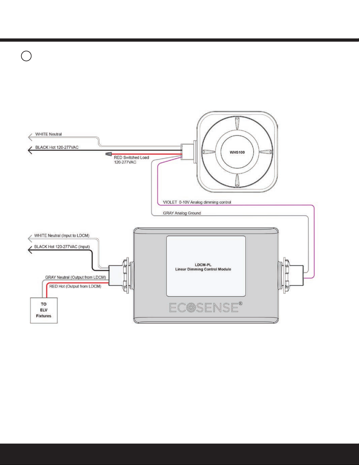
Redusing noise on low voltage (0-10V) wiring
After successfully completing the Installation Test the WHS100 is
ready to communicate with the Daintree Wireless Area Controller
(WAC) and the Daintree Controls Software (DCS) web-based
building controls management user interface.
A network join can be retriggered manually at any time by
resetting the WHS100:
• Reset to factory defaults: Press and hold the Utility button for
5 seconds. Release the button when the LEDs begin to ash
rapidly. This causes the device to leave any network to which it
is currently joined. Following the reset, the device attempts to
join a network. For more information about conguring
the lighting control network, see the instructions and on-line
help provided with the Daintree Controls Software application.
For more information about conguring the lighting control
network, see the instructions and on-line help provided with
the Daintree Controls Software web application.
The WHS100 is designed to be part of the Daintree Networked.
It should not be left to operate outside of the network indenitely.
The Daintree Controls Software web application provides many
control efciencies not otherwise available, including changing
operational parameters.
As shipped from the factory, before it is joined to the DCS network,
and after it joins the network but before it is congured into a zone,
the WHS100 controls the connected light as follows:
• During occupancy light is ON at 100%
• During vacancy an on/off light turns OFF, a dimming
light is reduced to 10%.
• Vacancy delay (Off Delay) is 10 minutes.
Functionality after Congured into a Zone
After the WHS100 is congured into a zone, it follows the control
strategy for the zone, including delay time, light levels, and other
features. The delay time is whatever the strategy dictates plus 20
seconds. For example, if the strategy is set for 8 minutes, the
vacancy delay is 8 minutes and 20 seconds.
There are no senstivity adjustments on the WHS100.
Contact Daintree support for information on how to change
the sensor sensitivity.
• Keep wiring as short as practical.
• Keep the signal lines separate from the mains voltage lines.
• Reduce the area created by the signal lines and the
GND return (i.e., keep them close together).
• If possible twist the signal line with the GND return.
14
IEEE Address Labels
A small plastic bag containing two small labels and the lens mask
is included with every sensor. The larger label with the WHS100’s
full IEEE address is the Fixture label. Afx this label to the outside
of the xture or sensor in a standard location where it can be seen
after installation and mounting.
Record IEEE Addresses
A marked-up copy of the facility oor plan showing the identity
and location of each wireless adapter (including associated xtures
and sensors) should be available after installation. This will
simplify and expedite the commissioning process.
Be sure that each sensor’s IEEE address (last 5 digits) is
recorded on the facility oor plan. Use the Plan label supplied
with the adapter or write the last 5 digits on the oor plan. This
information will be used during thecommissioning process.
For factory installation by xture manufacturers:
• Remove the Fixture label from its plastic bag, and afx to the
outside of the xture or sensor in a consistent location where it
can be seen after installation and mounting.
• Leave the Plan label (smaller label) in its plastic bag. Tape the bag
to the Fixture label or next to it .
15
Troubleshooting
No LEDs turn on when I press the Utility button.
• Check line voltage wiring Light doesn’t operate as expected
in Installation Test Mode.
• Make sure power is turned on to the xture circuit .
• Check all wiring between the xture and the sensor.
• Press the blue Utility button for 5 seconds to reset the unit.
Green motion detection LED does not activate when
walking through the coverage area.
• Check to see if the green LED turns on when you wave your
hand directly in front of the lens.
• If the LED turns on, check for objects or barriers obstructing
the sensor’s view of the coverage area.
Green LED ashes when the coverage area is vacant.
• Check for sources of hot air ow in the coverage area.
• See Placement Guidelines. Eliminate false trigger sources.
Light doesn’t turn Off after WHS100 joins the ZigBee network.
• Once the WHS100 is congured into a zone through DCS it
follows the Off Delay for the zone’s control strategy.
Light doesn’t turn Off after WHS100 is congured into a zone.
• Check the “Off delay” for the zone in the DCS.
• Check for other DCS scheduled events or manual
overrides that may be keeping the lights On.

Installation GuideDaintree®Wireless High Bay Sensor (WHS100)
7
16
Appendix 1: Installation Advisory
WHS100 Wiring for Emergency Power Circuits
In the diagram below, the WHS100 is powered by the Emergency
power circuit. While Regular power is supplied to the LVS model
RRU-X-UM, the WHS100 provides switched On/Off power to the
xture and controls dimming.
When the RRU-X-UM senses loss of Regular power, the RRU-X-UM
passes Emergency power directly to the xture and disconnects the
WHS100 switched output. Loss of Regular power to the RRU-X-UM
disables the WHS100 dimming control, so the xture operates at
maximum output.

Installation GuideDaintree®Wireless High Bay Sensor (WHS100)
8
17
Appendix 2: Installation Advisory
Control for Dimming ELV Fixtures: WHS100 wiring
to EcoSense Linear Dimming Control Module
This advisory shows the wiring connections between the
EcoSense LDCM-PL and the WHS100 to provide dimming control
to Electronic Low Voltage (ELV) lighting xtures within Daintree
Controls Software.

Installation GuideDaintree®Wireless High Bay Sensor (WHS100)
This equipment has been tested and found to comply with the
limits for a Class B digital device, pursuant to Part 15 of the FCC
Rules. These limits are designed to provide reasonable protection
against harmful interference in a residential installation. This
equipment generates, uses and radiates radio frequency energy
and, if not installed and used in accordance with the instructions,
may cause harmful interference to radio communications.
However, there is no guarantee that interference will not occur
in a particular installation. If this equipment does cause harmful
interference to radio or television reception, which can be
determined by turning the equipment off and on, the user is
encourage to try to correct the interference by one
or more of the following measures:
• Reorient or relocate the receiving antenna;
• Increase the separation between the equipment and receiver;
• Connect the equipment into an outlet on a circuit different
from that to which the receiver is connected;
• Consult the dealer or an experienced radio/TV technician
for help.
Product complies with Part 15 of the FCC Rules. Operation is
subject to the following two conditions: (1) This device may not
cause harmful interference, and (2) This device must accept any
interference received, including interference that may cause
undesired operation.
This Class B digital apparatus complies with Canadian ICES-003.
Cet appareil numérique de la classe B est conforme à la
norme NMB-003 du Canada.
These instructions do not purport to cover all details or variations in equipment nor to provide for every possible contingency to be met in connection with installation, operation
or maintenance. Should further information be desired or should particular problems arise which are not covered sufciently for the purchaser’s purposes, the matter should be
referred to GE Current, a Daintree company.
Questions:
Web: products.gecurrent.com
Phone: 1-866-855-8629
www.gecurrent.com
© 2021 Current Lighting Solutions, LLC. All rights reserved. GE and the GE monogram are trademarks of the
General Electric Company and are used under license. Information provided is subject to change without notice.
All values are design or typical values when measured under laboratory conditions.
DT109 (Rev. 03/29/2021
Input Power 120-277 VAC 50/60Hz
Load Rating 5A @ 120-277VAC
Load Types General Use, Electronic Ballast
Ballast/Driver Control: On/Off, 0-10V Dimming
Dimming Output 0-10V; 15mA (max sink)
Indicators Green LED (motion detection)
Red LED (off for normal operation)
Motion Sensor PIR technology
Power Measurement 2% accuracy (0.04~5A range)
Power Consumption 0.32W @120VAC, 0.58W @277VAC
Dimensions (w/out 3.54” L x 3.54” W x 1.78” H
mounting) (90mm L x 90mm W x 45.4mm H)
Radio Properties 2.4 GHz, +8dBm transmit power
Technology Wireless: ZigBee PRO (HA, BA)
Lenses Included 360° lenses (8ft, 20ft, 40ft), Aisle
Mask
Off-Delay Timer Congurable in CSM
Operating Environment -40°F to +158°F (-40°C to +70°C)
5-95% RH, non-condensing,
Indoor/Outdoor
Enclosure Watertight; IP66 rated*
Mounting Standard ½” knockout mount
Compliance
FCC Part 15, FCC ID: Z6G-DT357 CAN
ICES-3 (B)/NMB-3(B), IC: 10478A-
DT357 UL Listed
Specications
FCC Warning Message
Industry Canada (IC) Warning Message
CAUTION
RISK OF EXPOSURE IF BATTERY IS REPLACED BY AN
INCORRECT TYPE. DISPOSAL OF USED BATTERIES ACCORDING
TO THE INSTRUCTIONS
WHS100
18
19
Table of contents
Other Daintree Accessories manuals