Installation GuideDaintree®Networked Wireless Occupancy Sensor (WOS2-WM)
This equipment has been tested and found to comply with the
limits for a Class B digital device, pursuant to Part 15 of the FCC Rules.
These limits are designed to provide reasonable protection against
harmful interference in a residential installation. This equipment
generates, uses and radiates radio frequency energy and, if not
installed and used in accordance with the instructions, may cause
harmful interference to radio communications. However, there is
no guarantee that interference will not occur in a particular
installation. If this equipment does cause harmful interference to
radio or television reception, which can be determined by turning
the equipment off and on, the user is encourage to try to correct
the interference by one or more of the following measures:
• Reorient or relocate the receiving antenna;
• Increase the separation between the equipment and receiver;
• Connect the equipment into an outlet on a circuit different
from that to which the receiver is connected;
• Consult the dealer or an experienced radio/TV technician
for help.
Product complies with Part 15 of the FCC Rules. Operation is
subject to the following two conditions: (1) This device may not
causeharmfulinterference,and(2)Thisdevicemustacceptany
interference received, including interference that may cause
undesired operation.
These instructions do not purport to cover all details or variations in equipment nor to provide for every possible contingency to be met in connection with installation, operation
ormaintenance.Shouldfurtherinformationbedesiredorshouldparticularproblemsarisewhicharenotcoveredsufcientlyforthepurchaser’spurposes,themattershouldbe
referred to GE Current, a Daintree company.
Questions:
Web: products.gecurrent.com
Phone: 1-866-855-8629
www.gecurrent.com
©2021CurrentLightingSolutions,LLC.Allrightsreserved.GEandtheGEmonogramaretrademarksofthe
General Electric Company and are used under license. Information provided is subject to change without notice.
All values are design or typical values when measured under laboratory conditions.
DT106(Rev.03/30/2021
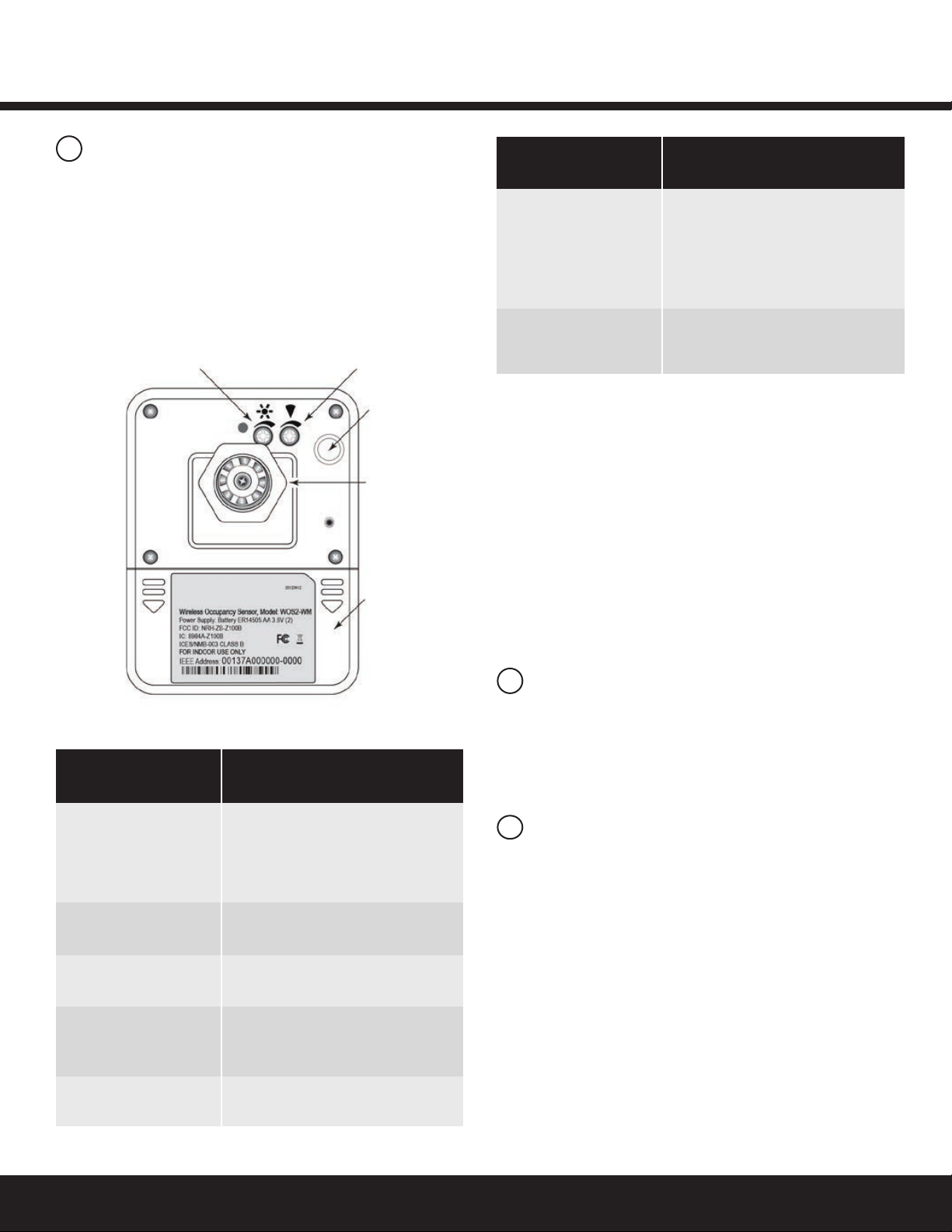
Power Supply 2)Lithium-thionylchloridebatteries
(Li-SOCl2)AA3.6V(included)
Battery Life 5 years (normal operation)
Radio Properties 2.4GHz,+7dBmtransmitpower
Sensor Coverage 110°,11m/36(WOS2-WM-W)
(maximum) 20°,30m/98(WOS2-WM-L)
Off-Delay Timer 14°to122°F(-10°to50°C)
Operating 14°Fto+122°F(-10°Cto50°C)
Environment Indoor use only
Compliance FCCPart15B,FCCID:NRH-ZB-Z100B
ICES/NMB-003ClassB,IC:8984A-Z100B
Mounting (2)Screwholesonbaseplate;
ceilingmount;twist-locksensor
Dimensions 3.6”Wx2.8”Hx3”D
(92mmWx70mmHx77mmD)Weight
(withoutbattery):3.32oz.(94g)
Specications
7FCC Warning Message
8Industry Canada (IC) Warning Message
CAUTION
RISK OF EXPOSURE IF BATTERY IS REPLACED BY AN
INCORRECT TYPE. DISPOSAL OF USED BATTERIES
ACCORDING TO THE INSTRUCTIONS.
WOS2-WM
6
Troubleshooting
No LEDs turn on when I press the Utility button.
•Check battery installation.
• Makesurebatteriesareoriented(+-)correctly.
The red Infrared Detection LED does not activate when walking
through the coverage area while in Installation Test mode.
•Check to see if the red LED turns on when you wave your
hand directly in front of the lens.
–IftheredLEDturnson,adjustthePIRSensitivitytrimpot
clockwise to increase sensitivity. Check for objects or
barriers obstructing the sensor’s view of the coverage area.
– If the red LED does not turn on, the Installation Test mode
may have timed out. Restart the Installation Test mode by
momentarily pressing the Utility button. The green LED
turnsonbriey,thentheredLEDasheswitheach
detection. Installation Test mode times out in 5 minutes.
The red LED ashes when nobody is moving in the
coverage area.
• AdjustthePIRsensitivitytrimpotcounter-clockwiseto
reduce sensitivity. Repeat the walk test.
• Checkforsourcesofhotairowinthecoveragearea.
•Review the Placement guidelines and eliminate false
trigger sources.
If lights do not turn Off after the WOS2-CM has Joined the
ZigBee network:
•Check the “Off delay” for the zone in the Daintree
ControlsSoftware.
• CheckforotherDCSscheduledeventsormanualoverrides
that may be keeping the lights On.