Dake SE-712 User manual

- 0 -
INSTRUCTION MANUAL
MODEL SE-712
METAL CUTTING BANDSAW MACHINE
724 Robbins Road
Grand Haven, MI 49417
Phone: 616-842-7110 800-937-3253
Fax: 616-842-0859
800-846-3253
Web: www.dakecorp.com
E-mail: customerservice@dakecorp.com

- 1 -
Table Of Contents Page No
1 Warning ….………………………………………………………………..… 2
2 Safety rules for all tools ..…………………………………………………… 3
3 Specification ………………………………………………………………… 6
4 Transportation of machine ………………………………………………..… 6
5 Installation …………………………………………………………………… 6
6 Minimum Room Space For Machine Operation …………………………… 7
7 Make proper tooth selection ……………………………………………….… 7
8 BI-Metal speeds and feeds .………………………………………………… 9
9 Assembly ……………………………………………………………………. 11
10 Operation …………………………………………………………………. 12
11 Blade guide bearing adjustment …..……………………………………… 15
12 Blade track adjustment .…………………………………………………… 16
13 Maintenance …………………..………………………………………………. 17
14 Lubrication ……………………………………………………………………. 18
15 Trouble Shooting ……………………………………………………………. .. 19-20
16 Circuit Diagram ……………………….……………………………………… 21/23
17 Electrical Specification Chart ………..………………………………………. 22/24
18 Parts Lists …………………………………………………………………… 25-31
19 Parts Breakdowns ………..……………………………………………………

- 2 -

- 3 -
WARNING: FAILURE TO FOLLOW THESE RULES
MAY RESULT IN SERIOUS PERSONAL INJURY
As with all machinery there are certain hazards involved with operation and use of the
machine. Using the machine with respect and caution will considerably lessen the
possibility of personal injury. However, if normal safety precautions are overlooked or
ignored, personal injury to the operator may result.
This machine was designed for certain applications only. We strongly recommends that
this machine NOT be modified and/or used for any application other than for which it was
designed. If you have any questions relative to its application DO NOT use the machine
until you contact with us and we have advised you.
Your machine might not come with a power socket or plug. Before using this
machine, please
Do ask your local dealer to install the socket or plug on the power cable end.
SAFETY RULES FOR ALL TOOLS
A. USER:
(1). WEAR PROPER APPAREL. No loose clothing, gloves, rings, bracelets, or other
jewelry to get caught in moving parts.
Non-slip foot wear is recommended. Wear protective hair covering to contain long hair.
(2). ALWAYS WEAR EYE PROTECTION. Refer to ANSLZ87.1 standard for appropriate
recommendations.
Also use face or dust mask if cutting operation is dusty.
(3). DON'T OVERREACH. Keep proper footing and balance at all times.
(4). NEVER STAND ON TOOL. Serious injury could occur if the tool is tipped or if the
cutting tool is accidentally contacted.
(5). NEVER LEAVE TOOL RUNNING UNATTENDED. TURN POWER OFF. Don't leave
tool until it comes to a complete stop.
(6). DRUGS, ALCOHOL, MEDICATION. Do not operate tool while under the influence of
drug, alcohol or any medication.
(7). MAKE SURE TOOL IS DISCONNECTED FROM POWER SUPPLY. While motor is
being mounted, connected or reconnected.
(8). ALWAYS keep hands and fingers away from the blade.
(9). STOP the machine before removing chips.
(10). SHUT- OFF power and clean the BAND SAW and work area before leaving the
machine.

- 4 -
B. USE OF MACHINE:
(1). REMOVE ADJUSTING KEYS AND WRENCHES. Form habit of checking to see that
keys and adjusting wrenches are removed from tool before turning it "on".
(2). DON'T FORCE TOOL. It will do the job better and be safer at the rate for which it
was designed.
(3). USE RIGHT TOOL. Don't force tool or attachment to do a job for which it was not
designed.
(4). SECURE WORK. Use clamps or a vise to hold work when practical. It's safer than
using your hand frees both hands to operate tool.
(5). MAINTAIN TOOLS IN TOP CONDITION. Keep tools sharp and clean for best and
safest performance. Follow instructions for lubricating and changing accessories.
(6). USE RECOMMENDED ACCESSORIES. Consult the owner's manual for
recommended accessories. The use of improper accessories may cause hazards.
(7). AVOID ACCIDENTAL STARTING. Make sure switch is in “OFF” position before
plugging in power cord.
(8). DIRECTIONOF FEED. Feed work into a blade or cutter against the direction of
rotation of the blade or cutter only.
(9). ADJUST AND POSITION the blade guide arm before starting the cut.
(10). KEEP BLADE GUIDE ARM TIGHT, A loose blade guide arm will affect sawing
accuracy .
(11). MAKE SURE blade speed is set correctly for material being cut.
(12). CHECK for proper blade size and type.
(13). STOP the machine before putting material in the vise.
(14). ALWAYS have stock firmly clamped in vise before starting cut.
(15). GROUNDALL TOOLS. If tool is equipped with three-prong plug, it should be
plugged into a three-hole electrical receptacle. If an adapter is used to accommodate
atwoprong receptacle, the adapter lug must be attached to a known ground. Never
removed the third prong.
C. ADJUSTMENT :
MAKE all adjustments with the power off. In order to obtain the machine. precision and
correct ways of adjustment while assembling, the user should read the detailed
instruction in this manual.
D. WORKING ENVIRONMENT:
(1). KEEP WORK AREA CLEAN. Cluttered areas and benches invite accidents.
(2). DON'T USE IN DANGEROUS ENVIRONMENT. Don't use power tools in damp or

- 5 -
wet locations, or expose them to rain. Keep work area well-lighted.
(3). KEEP CHILEREN AND VISITIORS AWAY. All children and visitors should be kept a
safe distance from work area.
(4). DON’T install & use this machine in explosive, dangerous environment.
E. MAINTENANCE:
(1). DISCONNECT machine from power source when making repairs.
(2). CHECK DAMAGED PARTS. Before further use of the tool , a guard or other part
that is damaged should be carefully checked to ensure that it will operate properly and
perform its intended function check for alignment of moving parts, binding of moving
parts, breakage of parts, mounting, and any other conditions that may affect its operation.
A guard or other part that is damaged should be properly repaired or replaced.
(3). DISCONNECT TOOLS before servicing and when changing accessories such as
blades, bits, cutters, etc.
(4). MAKE SURE that blade tension and blade tacking are properly adjusted.
(5). RE-CHECK blade tension after initial cut with a new blade.
(6). TO RPOLONG BLADE LIFE ALWAYS release blade tension at the end of each
work day.
(7).CHECK COOLANT DAILY Low coolant level can cause foaming and high blade
temperatures. Dirty or week coolant can clog pump, cause crooked. Cast, low cutting rate
and permanent blade failure. Dirty coolant can cause the growth of bacteria with ensuing
skin irritation.
(8). WHEN CUTTING MAGNESIUM NEVER use soluble oils or emulsions(oil-water mix)
as water will greatly intensify any accidental magnesium chip fire. See your industrial
coolant supplier for specific coolant recommendations when cutting magnesium.
(9). TO PRNMT corrosion of machined surfaces when a soluble on is used as coolant,
pay particular attention to wiping dry the surfaces where fluid accumulates and does not
evaporate quickly, such as between the machine bed and vise.
F. SPECTIFIED USAGE:
This machine is used only for general metals cutting within the range of cutting capacity.
G. NOISE:
A weighted sound pressure level : 80 dB.
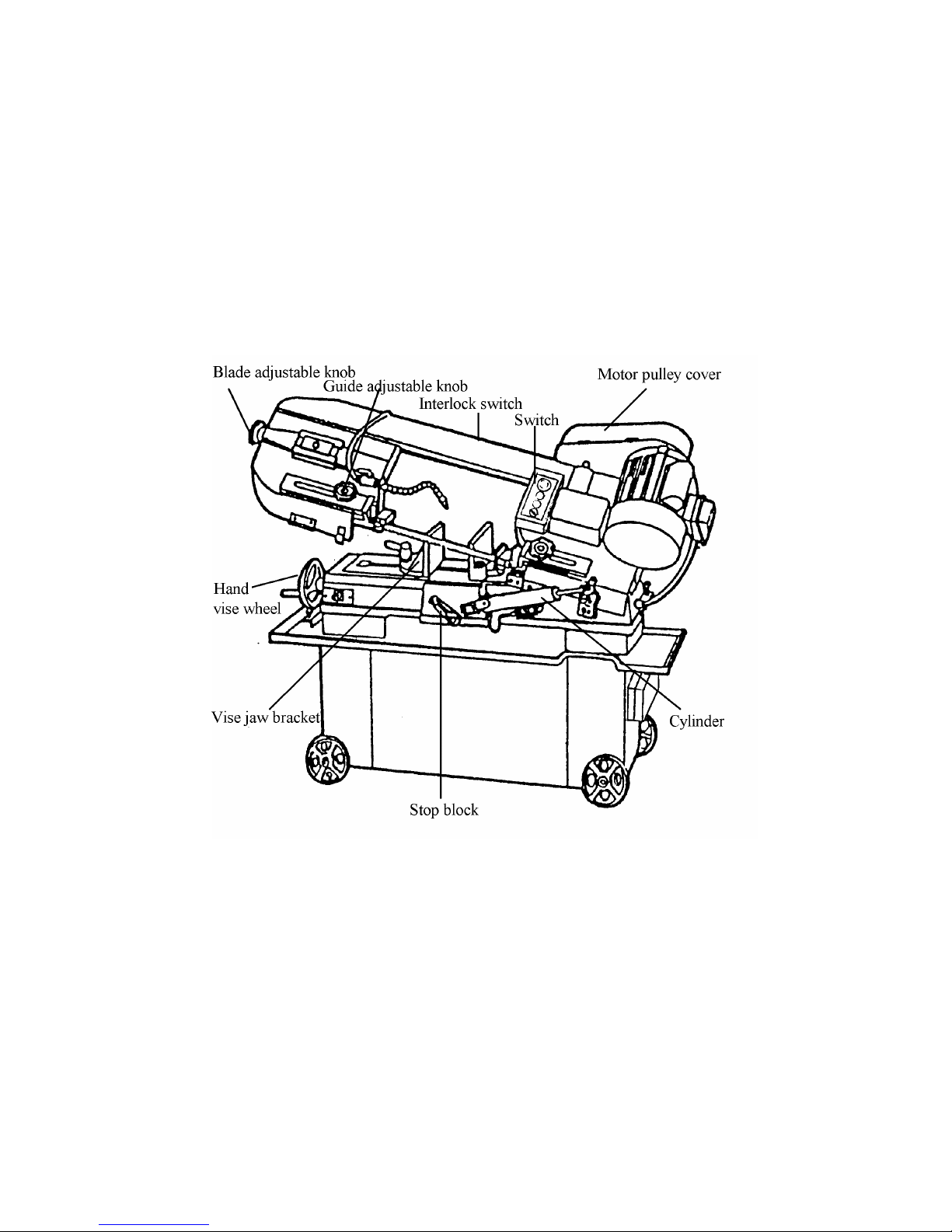
H. SAFETY DEVICE:
By the time the saw arm cover is opened, the interlock switch will function to stop the
machine. Do not remove this switch from machine for any reason, and check it's function

- 6 -
frequently.
1. SPECIFICATION
MOTOR 0.55KW ( 3/4HP )
60Hz
26 40 55 72 MPM
Saw Blade Speed 50Hz 21 33 45 60 MPM
Blade Size 19.05x0.8x2362 ( Carbon Blade )
Dimension LxWxH (mm) 1229x432x965
N.W / G.W (kgs) 125 / 150
(mm) 178
90° (mm) 178x305
(mm) 115
Working Capacity
45° (mm) 115x180
Packing Measurement (mm)
LxWxH
1270 x 470 x 965 mm
Overall height (w/o stand)
1092mm(43")
Noise 80 dB MAX
2. TRANSPORTATION OF MACHINE:
Unpacking
1. Transportation to desired location before unpacking, please use lifting jack.(Fig.
B)
2. Transportation after unpacking, please use heavy duty fiber belt to lift up the
machine.
Fig. B
ALLWAYS KEEP PROPER FOOTING & BALANCE WHILE MOVING THIS MACHINE.
Installation:
As this machine weights 125 kg. It is recommended that the machine shall be
transported, with help of lifting jack.

- 7 -
Transportation Recommendation:
(1). Tighten all locks before operation.
(2). ALWAYS Keep proper footing & balance while moving this 125kgs machine, and
only use heavy duty fiber belt to lift the machine as Fig. A
(3). TURN OFF the power before wiring, & be
sure machine in proper grounding, Overload &
circuit breaker is recommended for safety
wiring.
(4). CHECK carefully if the saw blade is running
in
counter-clockwise direction if not , reverse the
wiring per circuit diagram then repeat the
running
test.
(5). KEEP machine always out from sun, dust, wet, raining area.
3. MINIMUM ROOM SPACE FOR MACHINE OPERATION
4. MAKE PROPER TOOTH SELECTION
For maximum cutting efficiency and lowest cost per cut, it is important to select the
blade with the right number of teeth per inch (TPI) for the material being cut. The material
size and shape dictate tooth selection.

- 8 -
TOOTH
SELECTION
You need to consider:
1.The width of the cut. That is, the distance in the cut that each tooth must travel from the
point it
enters the workpiece until it leaves the workpiece, and
2.The shape of the workpiece.
Squares, Rectangles, Flats (Symbol : )
Locate the width of cut on the chart. (Inches on the outer circle and millimeters
on the inner circle.) Select the tooth pitch on the ring marked with the square
shape which aligns with the width of cut.
EXAMPLE: 6" (150mm) square, use a 2/3 Vari-Tooth.
Round Sollds (Symbol : )
Locate the diameter of your workpiece on the chart. Select the tooth pitch on the
ring marked with the round shape which aligns with the size of stock you are
cutting.
EXAMPLE: 4" (100mm) round, use a 3/4 Vari-Tooth.
Tubing, Pipe, Structurals( Symbol : O H ^ )
Determine the average width of cut by dividing the area of the workpiece by the
distance the saw blade must travel to finish the cut. Locate the average width of
cut on the chart. Select the tooth Ditch on the ring marked with the tubing and
structural shape which aligns with the average width you are cutting.
EXAMPLE: 4"(100mm) outside diameter, 3"(75mm) inside diameter tubing.
4"(100mm) OD =12.5 sq.ln. (79cm
2
)
3"(75 mm ) ID = 7.0 sq.ln. (44cm
2
)
Area = 5.5 sq.ln. (35cm
2
)
5.5 sq.ln. (35cm
2
) / 4" (100mm) distance =1.38(35mm) average width
1.38" (35mm), use a 4/6 Vari-Tooth

- 9 -
NOTE: The band speed and cutting rate recommendations presented on this
chart are approximations and are to be used as a starting point for most
applications. For exact sawing parameters' consult your saw blade supplier.
5. BI-METAL SPEEDS AND FEEDS
These figures are a guide to cutting 4"(100mm) material (with a 314 Vari-Tooth) when
using a cutting fluid.
Increase Band Speed: 15% When cutting 1/4"(6.4mm) material (l0/l4 Vari-Tooth)
12% When cutting 3/4"(19 mm) material (6/10 Vari-Tooth)
10% When cutting 1-1/4"(32 mm) material(5/8 Vari-Tooth)
5% When cutting 2-1/2" (64 mm) material(4/6 Vari-Tooth)
Decrease Band Speed: 12% When cutting 8"(200mm) material(2/3 Vari-Tooth)
BAND SPEEDMATERIAL ALLOY
ASTM NO. FT./MIN M/MIN
173,932
314 96
330,365
284 87
623,624
264 81
230,260,272
244 74
280,264,632,655
244 74
101,102,1
10,122,172 234 71
1751,182,220,510
234 71
625,706,715,934
234 71
630
229 70
Copper
Alloy
811
214 65
1117
339 103
1137
289 88
1141,1144
279 85
1141 HI STRESS
279 85
1030
329 100
1008,1015,1020,1025
319 97
1035
309 94
10
18,1021,1022 299 91
1026,1513
299 91
A36(SHAPES),1040
269 82
1042,1541
249 76
1044,1045
219 67
1060
199 61
Carbon
Steel
1095
184 56

- 10 -
8615,8620,8622
239 73
4340,E4340,8630
219 67
Ni
-Cr-Mo
Alloy Steel
8640,
199 61
Ni
-Cr-Mo
Alloy Steel
E93
10 174 53
A
-6 199 61
A
-2 179 55
A
-10 159 49
D
-2 90 27
Tool Steel
H
-11,H-12,H-13 189 58
420
189 58
430
149 46
410,502
140 43
414
115 35
431
95 29
440C
80 24
304,324
120 36
304L
115 35
347
110 33
316,316L
100 30
Stainless
Steel
416
189 58
TELLTALE CHIPS
Chips are the best indicator of correct feed force. Monitor chip information and adjust
feed accordingly.
Thin or powdered chips – increase feed rate or reduce
band speed.
Burned heavy chips – reduce feed rate and/or band
speed.
Curly silvery and warm chips – optimum feed rate and
band speed.

- 11 -
6. ASSEMBLY
A 3/4 HP, motor, split phase or capacitor-start it recommended for best economical
performance.
Counterclockwise rotation is required. Note that rotation can be reversed by ollowing
directions
given on terminal or nameplate.
(1). Assemble the motor Mounting plate to the head using the long bolt Note that the flat
side of the plate faces up.
(2). Assemble the guard plate to the head using the screw and Lock Washer and the
Carriage Bolt Washer and Wing Nut are used to secure the motor mounting plate to the
Guard plate through the slotted hole in the Guard plate. These components also serve to
position and lock the motor in place for proper speed/ belt adjustment.
(3). Place the spacer over the long Bolt and secure it wit the nut .
(4). Secure the Motor to the Motor Mounting plate with the four bolts and nuts. Note, that
the motor shaft is placed through the large opening in the Guard plate and must be
pareallel with the drive Shaft.
(5). Assemble the Motor Pulley, the smaller of the two provided, to the motor shaft Note,
the larger diameter must be closest to the motor.
Do not tighten the set screw.
(6). Assemble the Driven Pulley, the larger of the two provided, to the protruding drive
Shaft Note the small diameter must be closest to the bearing.
Do not tighten the set screw.
(7).Place the belt into one of the pulley grooves and the other end into the respective
grooves of the second pulley.
(8) Line up the belt and both pulleys such that the belt is running parallel in the pulley
grooves.
(9).Tighten the set screws of both pulleys in this position.
(10). Place the belt into proper pulley combination for proper blade speed. See material
cutting Chart .
(11). Adjust the position of the Motor to obtain approximately 1/2" depression in the belt
when applying pressure with your thumb.
(12). Tighten the head screw Holding the Motor Mounting plate to the Guard plate.
(13). Connect the Electrical Harness to the motor terminal box. The motor should be
protected with a time delay fuse or circuit breaker with a rated amperage slightly greater
than the full load amperage of the motor.

- 12 -
7. OPERATION
WORK SET UP
(1). Raise the saw head to vertical position.
(2). Open vise to accept the Piece to be cut by rotating the wheel at the end the base.
(3). Place workpiece on saw bed. If the piece is long, support the end.
(4). Clamp workpieced securely in vise.
WORK STOP ADJUSTMENT
(1). Loosen the thumb screw holding the work stop casting to the shaft.
(2). Adjust the work stop casting to the desired length position.
(3). Rotate the work stop to as close to the bottom of the cut as possible.
(4). Tighten thumbscrew.
(5). DO NOT ALLOW the blade to rest on the work while the motor is shut off.
BLADE SPEEDS
When using your Band saw always change the blade speed to best suit the material
being cut the material Cutting Shart givers suggested settings for several materials.
Speed F.P.M Belt Groove Used
60Hz 50Hz
Material
A B A B
Motor
Pulley
Saw
Pulley
Tool, Stainless
Alloy Steels
Bearing Bronze
85 98 70 81 Small Largest
Medium to High
Carbon Steels
Hard Brass or Bronze
130
164
110
135
Medium Large
Low to Medium
Carbon Steel
Soft Brass
180
246
150
203
Large Medium
Aluminum Plastic 235
328
195
270
Largest Small
A: For 712N with carbon blade
B: For 712R, 712DR, 712N with Bi-Metal blade.

- 13 -
BLADE DIRECTION OF TRAVEL
Be sure the Made is assembled to the pulleys such that the vertical edge engages the
work piece first.
BLADE MOVEMENT
Blade Direction
STARTING SAW
Switch button function description (FOR CE ONLY)
CAUIION: NEVER OPERATE SAW WITHOUT BLADE GUARDS IN PLACE.
Be sure the blade is not in contact with the work when the motor is started. Start the motor,
allow the saw to come to full speed, then begin the cut by letting the head down slowly
onto the work. DO NOT DROP OR FORCE. Let the weight of the saw head provide the
cutting force. The saw automatically shuts off at the end of the cut.
BLADE SELECTION
A 8-tooth per inch, general-use blade is furnished with this metal Cutting Band Saw.
Additional blades in 4, 6, 8, and 10 tooth sizes are available. The choice of blade pitch is
governed by the thinness of the work to be cut: the thinner the workpiece, the more teeth
advised. A minimum of three (3) teeth should angage the workpiece at all times for proper

- 14 -
cutting If the teeth of the Blade are so far apart that they straddle the work, severe
damage to the workpiece and to the Made can result .
CHANGING BLADE
Raise saw head to vertical position and open the blade guards. Loosen tension screw
knob sufficiently to allow the saw blade to slip off the wheels. Install the new blade with
teeth slanting toward the motor as follows:
(1). Place the blade in between each of the guide bearings.
(2). Slip the blade around the motor pulley (bottom) with the left hand and hold in
position.
(3). Hold the blade taut against the motor pulley by pulling the blade upward with the right
hand
which is placed at the top of the Made.
(4). Remove left hand from.bottom pulley and place is at the top aide of the Made to
continue the
application on the upward pull on the blade.
(5). Remove right hand from blade and adjust the position of the top pulley to permit left
hand to slip the blade around the pulley using the thumb, index and little finger as
guides.
(6). Adjust the blade tension knob clockwise until it is just right enough so no blade
slippage occurs. Do not tighten excessively.
(7). Replace the blade guards.
(8). Place 2-3 drops of oil on the blade.
USAGE OF THE OUICK VISE
The workpiece is placed between the
vise jaws with the amount to be cut-off
extending out past the blade. Your
machine is equipped with a "quick
action" vise jaw which allows you to
instantly position the moveable vise
jaw (B). Simply turn handwheel (A)
counterclockwise 1/2 turn and move
the vise jaw (B) to the desired position.
Then tighten the vise jaw (B) against
the work-piece by turning hand-wheel clockwise.
QUICK VISE ADJUSTMENT FOR ANGLE CUT
(1). Loosen the A. B. C. D. Screw.

- 15 -
(2). Adjust rear vise to the threaded hole position. (E)
(3). Set the scale to the desired angle.
(4). Adjust the front vise (F) to parallel the rear vise(E)
(5). Tighten the A. B. C. D. Screw.
8. BLADE GUIDE BEARING ADJUSTMENT
ATTENTION: This is the most important adjustment on your saw. It is impossible to get
satisfactory work from your saw if the blade guides are not properly adjusted. The blade
guide bearings on your metal. Cutting Band Saw are adjusted and power tested with
several test cuts before leaving the factory to insure proper setting The need for
adjustment should rarely occur when the saw is used properly. If the guides do get out of
adjustment though, it is extremely important to readjust immediately. If improper
adjustment in maintained, the blade will not cut straight, and if the situation is not
corrected it will cause serious blade damage. Because guide adjustment is a critical factor
in the performance of your saw, it is always best to try a new blade to see if this will
correct poor cutting before beginning to adjust. If a blade becomes dull on one side sooner
than the other, for example, it will begin cutting crooked. A blade change will correct this
problem the gJide adjustment will not. If a new blade does not correct the problem, check
the blade guides for proper spacing.
NOTE: There should be from 000 (just touching) 001 clearance between the blade and
guide bearings to obtain this clearance adjust as follows:
1. The inner guide bearing is fixed and cannot be adjusted.
2. The outer guide bearing is mounted to an eccentric bushing and can be adjusted.
3. Loosen the nut while holding the bolt with an Alien wrench.
4. Position the eccentric by turning the bolt to the desired position of clearance.
5. Tighten the nut.
6. Adjust the second blade guide bearing in the same manner.
REMARK:
1. Adjust the tension of blade until the back of the blade(A) against the blade wheel

- 16 -
(front) lightly.
2. Be sure the nut (E) is tightened.
3. Turn the eccentric shaft(B) counterclockwise, when the bearing(D) touches the saw
blade properly, tighten the nut(E).
4. To adjust, loosen set screw(F) and move the blade adjustable up or down until it
lightly
touches the back of the blade(A).
5. Repeat 1. 2, 3, and 4 steps to adjust the other side's blade guide bearings(G).
6. Correct the base and blade to be a vertical position with a scale. If necessary,
loosen set screw(F).
7. Set down the blade frame, correct the jaw vise(H) and blade to be a vertical
position with a scale then tighten the set screws (I).
8. Loosen set screw (K), move front jaw vise (J) to against rear jaw vise(H) tightly.
Finish correcting by tighting set screw(K).
Fig. 1
Fig. 2
9. BLADE TRACK ADJUSTMENT
(1). Open the blade guard.
(2). Remove the blade guide assemblies (top and bottom)

- 17 -
(3). Loosen the hex head screw in the tilting machanism to a point where it is loose but
snug.
(4). With the machine running, adjust both the set crew and blade tension knob
simultaneously to keep constant tension on the blade. The set screw and blade
tension knob are always turned in opposite directions, ie, when one is turned
clockwise the other is turned counterclockwise.
The blade is tracking properly when the back side just touches the shoulder of pulley
or a slight gap appears near the center line of the pulley. Care should be taken not to
over-tighten the saw blade since this will give a false adjustment and limit life of the
blade.
(5). Tighten the hex head screw in tilting mechanism. IMPORTANT: Sometimes in trying
to make this critical adjustment it is possible to cause the basic setting to be
misaligned. Should this occur, proceed as follows:
a. Loosen the set screw and back it out as far as it can go and still remain in the
threaded hole.
b. Turn the hex head screw clockwise until it stops (do not tighten).
c. Turn the set screw clockwise until it bottoms, then continue for half a turn and
check the tracking by turning on the machine.
d. If further adjustment is required, go back to step 4.
(6). Turn off power to the machine.
(7). Replace the clade guide assemblies--it may be necessary to loosen the blade
tension alightly.
(8). Adjust the vertical position of blade guide bearing assemblies so that the back side of
the blade just touches the ball bearing.
(9). Make a final run to check tracking. It required, touch up adjustment (See stop 4)
(10). Replace the blade guards.
10. MAINTENANCE
CAUTION: MAKE CERTAIN THAT THE UNIT IS DISCONNECTED FROM THE POWER
SOURCE BEFORE ATTEMPTING TO SE RV ICE OR REMOVE ANY COMPONENT.
That's easier to keep machine in good condition or best performance by means of
maintaining it at any time than remedy it after it is out of order.
(1) Daily Maintenance (by operator)
(a) Fill the lubricant before starting machine everyday.
(b) If the temperature of spindle caused over-heating or strange noise, stop machine
immediately to cheek it for keeping accurate performance.
(c) Keep work area clean; release vise, cutter, work-piece from table; switch off power
source; take chip or dust away from machine and follow instructions lubrication or

- 18 -
coating rust proof oil before leaving.
(2) Weekly Maintenance
(a) Clean and coat the leading screw with oil.
(b) Check to see if sliding surface and turning parts lack of lubricant. If the lubricant is
insufficant, fill it.
(3) Monthly Maintenance
(a) Check if the fixed portion llave been loose.
(b) Lubricate bearing, worm, and worm shaft to avoid the wearing.
(4) Yearly Maintenance
(a) Adjust table to horizontal position for maintenance of accuracy.
(b) Check electric cord, plugs, switches at least once a year to avoid loosening or
wearing.
LUBRICATION
Lubricate the following components using SAE-30 oil as noted.
(1). Ball-bearing none.
(2). Driven pulley bearing 6-8 drops a week.
(3). Vise lead screw as needed.
(4). The drive gears run in an oil bath and will not require a lubricant change more often
than once a year, unless the lubricant is accidentally contaminated or a leak occurs
because of improper
replacement of the gear box cover. During the first few days of operation, the worm gear
drive will run hot. Unless the temperature exceeds 200F., there is no cause for
alarm.
The following lubricants may be used for- the gear box:
Atlantic Refinery Co. Mogul Cyl. Oil
Cities Service Gptimus No. 6
Gulf Refinery Co Medium Gear Oil

- 19 -
11. TROUBLE SHOOTING
Symptom
Possible Cause(s) Corrective Action
Excessive Blade
Breakage
1. Materials loosen in vise.
2. Incorrect speed or feed
3.Blade teeth spacing too large
4. Material too coarse
5. Incorrect blade tension
6.Teeth in contact with material
before saw is started
7. Blade rubs on wheel flange
8. Miss-aligned guide bearings
9. Blade too thick
10 Cracking at weld
1. Clamp work securely
2. Adjust speed or feed
3. Replace with a small
teeth spacing blade
4. Use a blade of slow
speed and small teeth
spacing
5. Adjust to where blade just
does not slip on wheel
6. Place blade in contact
with work after motor is
starred
7. Adjust wheel alignment
8. Adjust guide bearings
9. Use thinner blade
10. Weld again, note the
weld skill.
Premature Blade
Dulling
1. Teeth too coarse
2. Too much speed
3. Inadequate feed pressure
4.Hard spots or scale on material
5. Work hardening of material.
6.Blade twist
7. Insufficient blade
8. Blade slide
1. Use finer teeth
2. Decrease speed
3. Decrease spring tension
on side of saw
4. Reduce speed, increase
feed pressure
5. Increase feed pressure by
reducing spring tension
6. Replace with a new blade,
and adjust blade tension
7. Tighten blade tension
adjustable knob
8. Tighten blade tension
Unusual Wear on
Side/Back of Blade
1. Blade guides worn.
2. Blade guide bearings not
adjust properly
3. Blade guide bearing bracket
is loose
1. Replace.
2. Adjust as per operators
manual
3. Tighten.
Other manuals for SE-712
1
Table of contents
Other Dake Saw manuals

Dake
Dake SE-912 Operating and maintenance manual

Dake
Dake SE-912 User manual

Dake
Dake 14-10 User manual

Dake
Dake SXC 988040 User manual

Dake
Dake Euromatic 370 S User manual

Dake
Dake E-16 User manual

Dake
Dake Technics 250 Operating and maintenance manual

Dake
Dake Trademaster User manual

Dake
Dake E-16 User manual

Dake
Dake SE-5X6 RCT User manual

Dake
Dake V-26 User manual

Dake
Dake V-16 User manual

Dake
Dake F-16 User manual

Dake
Dake CUT 250 COLD SAW User manual

Dake
Dake Technics 350 SA User manual

Dake
Dake LAGUNA 14CX User manual

Dake
Dake JH-10 User manual

Dake
Dake SL913 TW Quick start guide

Dake
Dake SE-10 DM User manual

Dake
Dake Technics 350 CE Operating and maintenance manual