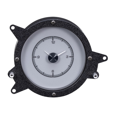
Dakota Digital VLC Series User manual

1 MAN # 650462:A
OPERATION MANUAL
FOR
VLC-xxx clocks
Analog Clock module for use with VHX systems
CONNECTION DIAGRAM:
ACC. POWER
CONST. POWER
GROUND
TACH
WARN
SPD +
SPD SND
SPD -
SPD OUT
SW2 (-)
SW1 (-)
ADJ SND
ADJ -
WTR SND
WTR -
OIL +
OIL SND
OIL -
FUEL +
FUEL SND
FUEL -
WAIT (+)
CRUISE (-)
GEAR (1 WIRE)
4x4 (-)
RIGHT (+)
LEFT (+)
HIGH (+)
BRAKE (-)
CHECK ENG (-)
VHX
CONTROL BOX
CABLE AUX.
I/O
DISPLAY
www.dakotadigital.com
605-332-6513
DIM (+)
RED
Connection for all
auxiliary displays
Use any open jack
VHX
control
box
Connect to
constant +12V
circuit (battery)
OR
Connect as shown in VHX manual
WIRING:
CAT-5 CABLE:
A CAT-5 cable comes with the kit to connect the VLC to one of the empty jacks on the VHX control box. This
cable provides the ground connection for the VLC clock through the VHX control box ground. If a longer or shorter
cable is desired, a standard CAT-5, CAT-5E or CAT-6 PATCH cable of any length 7 feet or shorter may be
used. Do not use a cable longer than 7 feet or a “crossover” cable as these may cause improper operation or
device damage.
NOTE: Some VHX systems come with a VLC unit integrated into the kit. These systems may already have the
CAT-5 connection made inside the system. Other systems may require a CAT-5 jumper to go from the VLC to a
jack on another part of the VHX system. Check the VHX system install manual for more specific CAT-5
connection instructions for these systems.
BATTERY WIRE:
A single RED wire harness with connector is provided to plug into the back of the VLC. This red wire should be
connected to a circuit that has +12v at all times (battery connection). This provides the power for the VLC clock to
operate and keep time when the key is turned off. A good place to make this connection is the same circuit that
the VHX control box gets its constant power.

2 MAN # 650462:A
OPERATION:
CONNECTING POWER:
When the power is first connected to the VLC, the hands on the clock will move quickly around the dial until they
point to 12:00. This is normal and is how the VLC calibrates the location of the clock hands. After this calibration
mode, the VLC will begin to keep time from 12:00 until the time is updated by the VHX system.
KEY OFF/ON MODE:
When the key is turned off, the VLC will use its internal clock to keep track of time and move the hands
accordingly. When the key is turned on, the VLC will update its time using time data it receives from the VHX
system. If this time is different than the time on the VLC, the clock hands will move rapidly either ahead or back to
adjust to this new time.
Large differences in time that cause fast hand movement can be caused by several things. If the constant power
is lost on the VHX control box, its clock will be reset changing its time in relation to the VLC stored time. Similarly
if the time is provided by a BIM expansion module, constant power loss to this module will cause a clock reset.
Also if the BIM expansion module that provided time became disconnected from the BIM connector on the VHX
control box, the VLC will revert to getting the time data from VHX control box and this time may be different than
the time previously provided by the BIM module.
SETTING THE CLOCK:
The VLC will automatically set itself from clock data in the VHX system. Simply connect the VLC to the VHX
system and connect constant power to the VLC. When the key is turned on, it will adjust the clock hands to match
the time data from the VHX system.
NO CLOCK BIM MODULES
If time data is not provided by any of the connected BIM expansion modules, the VHX system time is used to
update the VLC time. Use the following steps to adjust the time if the VHX system time is being used.
1. Turn the key on to power on the VHX system.
2. Press and release the VHX switch until clock screen is displayed in VHX message center. (If the clock
screen display has been disabled in VHX setup, it will need to be re-enabled to set the clock. It can again
be disabled after the clock is set if so desired. See VHX operations manual for details.)
3. Press and hold the VHX switch to enter clock set mode.
4. Adjust time by pressing and releasing switch, save setting by holding switch.
5. VLC hands will adjust automatically to the time as it is changed.
BIM MODULES WITH CLOCK
Several BIM expansion modules can provide time data to the VHX system. The BIM-16-1 clock module and the
GPS-50-2 compass module are two examples of this. If this type of module is being used and the clock channel is
turned on, the VLC will update from this time instead of the VHX system time. To set the VLC clock when using a
BIM time channel, use the following steps (see VHX operations manual or the BIM expansion module manual for
more details on setting BIM channel time):
1. While holding VHX switch 1, turn the key on to turn on VHX system and enter setup.
2. Press and release switch 1 until the SETUP BIM option and press and hold switch to select it.
3. Press and release switch until SETUP option and press and hold to select it.
4. Press and release switch until the clock BIM channel is displayed. Press and hold to select.
5. Press and hold to select “CLOCK” label. Message will show current time. Release switch.
6. Press and release to change time. Press and hold to set.
7. Exit setup mode by turning key off when completed.
NOTE: The VLC may not track every change when setting but will update to new time with next key on.

3 MAN # 650462:A
SETTING CLOCK WHEN ALL 16 BIM CHANNELS ARE IN USE:
If all 16 available BIM channels are used for expansion modules and none of the channels are clock data, the
VLC unit will not be able to receive time updates from the VHX system. However, the VLC unit is still able to keep
time after it is set without these updates. In order to set the VLC time when all 16 channels are used, follow this
procedure:
1. Disconnect one or more BIM expansion modules from the BIM expansion port on the VHX control box.
2. Make sure the VLC is properly installed and connected to the VHX system.
3. Turn the key on. If the VHX system time is correct, the VLC will automatically update to the correct time.
4. If the VHX system time is not the correct time, change one of the screens to display the time and set to the
correct time by holding the switch (see VHX operations manual for details on clock setting). The VLC will
adjust to match the time as you adjust it.
5. Turn the key off.
6. Reconnect the BIM expansion modules.
7. The VLC will keep time using its internal clock as long it stays connected to its constant power and a
properly grounded VHX control box. To make later adjustments to the VLC time, repeat this procedure as
needed.
MULTIPLE BIM CLOCK CHANNELS:
If more than one connected BIM expansion module is providing a time channel, there will be multiple clock
sources for the VLC. In this case, the VLC will attempt to update its time from more than one source. This will
cause the clock hands to rapidly move back and forth as the internal clock is continually changed in the VLC.
To solve this problem, either disconnect any extra BIM expansion modules with clocks or disable the clock
channels on all but one of the BIM expansion modules so only one clock source is seen by the VLC.
ADJUSTING DIAL BRIGHTNESS:
The illumination for the VLC clock dial is controlled by the VHX control box. The brightness level will match the
brightness level of the other VHX displays. To adjust this brightness level, use the VHX control box setup menu. A
brightness level can be set for day time and night time (based on the DIM line to the VHX control box.) For more
details on illumination settings, see the VHX operations manual.
VLC Specifications
SUPPLY
Voltage Range (BAT)
8 to 18 V
CURRENT DRAW (BAT)
IGN off
Approximately 0.5 mA
IGN on
< 75 mA
SERVICE AND REPAIR
DAKOTA DIGITAL offers complete service and repair of its product line. In addition, technical consultation is available to help you work through any questions or
problems you may be having installing one of our products. Please read through the Troubleshooting Guide. There, you will find the solution to most problems.
Should you ever need to send the unit back for repairs, please call our technical support line, (605) 332-6513, to request a Return Merchandise Authorization
number. Package the product in a good quality box along with plenty of packing material. Ship the product by UPS or insured Parcel Post. Be sure to include the RMA
number on the package, and include a complete description of the problem with RMA number, your full name and address (street address preferred), and a telephone number
where you can be reached during the day. Any returns for warranty work must include a copy of the dated sales receipt from your place of purchase. Send no money. We will
bill you after repair. Dakota Digital Limited Lifetime Warranty
DAKOTA DIGITAL warrants to the ORIGINAL PURCHASER of this product that should it, under normal use and condition, be proven defective in material or
workmanship for the lifetime of the original vehicle it was installed in, such defect(s) will be repaired or replaced at Dakota Digital’s option.
This warranty does not cover nor extend to damage to the vehicle’s systems, and does not cover diagnosis, removal or reinstallation of the product. This Warranty
does not apply to any product or part thereof which in the opinion of the Company has been damaged through alteration, improper installation, mishandling, misuse, neglect,
or accident. Dakota Digital assumes no responsibility for loss of time, vehicle use, owner inconvenience nor related expenses.
Dakota Digital will cover the return standard freight once the product has been evaluated for warranty consideration, however the incoming transportation is to be covered by
the owner. This Warranty is in lieu of all other expressed warranties or liabilities. Any implied warranties, including any implied warranty of merchantability, shall be limited to
the duration of this written warranty. No person or representative is authorized to assume, for Dakota Digital, any liability other than expressed herein in connection with the
sale of this product.

4 MAN # 650462:A
TROUBLESHOOTING:
Problem
Possible cause
Solution
Clock time never changes
Battery wire not connected
VHX connection not made
Check that the battery wire is plugged into back of
VLC unit and is connected to a constant +12V circuit
Check that a CAT-5 cable connects from the back of
VLC to one of the connectors on the VHX control
box or a VHX display
Backlights always on when key
on, clock hands not keeping
time
Battery wire not connected
Check that the battery wire is plugged into back of
VLC unit and is connected to a constant +12V circuit
Clock hands spin to 12:00 every
time key turned on
Battery wire connected to switched
power not constant
VHX control box constant power
connected to switched power
No constant power on clock BIM
expansion module
Move battery wire from the switched +12v circuit to a
circuit that has constant +12v
Move BAT connection for VHX control box from
switched +12V circuit to circuit with constant +12V
Check power connections on BIM clock module for
correct connections (see BIM manual)
Clock doesn’t keep track of time
when key is off
Battery wire not connected
Battery wire connected to switched
power not constant
Check that battery wire is connected to a constant
+12V circuit
Move battery wire from the switched +12v circuit to a
circuit that has constant +12v
Clock will not adjust time to
match VHX system time
Battery wire not connected
All 16 BIM channels are used and
none of the channels is a clock
No data is on the VHX
communication line.
VHX connection not made
Check that battery wire is connected to a constant
+12V circuit
Remove or disable an unused BIM channel. If all the
channels are to be used, see “Setting the clock
when all 16 BIM channels in use” in this manual.
Verify displays of VHX system are working. If they
display “NO DATA…” inspect the CAT-5 cables and
the BIM expansion cables for damage and proper
connection.
Check that a CAT-5 cable connects from the back of
VLC to one of the connectors on the VHX control
box or a VHX display
Clock hands move erratically or
jump between two different
times
Multiple clock sources are present in
the VHX system
Remove additional Clock BIM sources by
disconnecting the BIM module or disabling the clock
channel for all but one BIM module.
Backlights flash continually with
the key on and time doesn’t
change.
VLC internal clock is damaged or not
functioning properly
Call Dakota Digital for RMA number to return
product for repair
WARNING: This product can expose you to chemicals including lead, which is known to the State of
California to cause cancer and birth defects or other reproductive harm. For more information go to
www.P65Warnings.ca.gov
4510 W. 61st St. North Phone (605) 332-6513
Sioux Falls, SD 57107 Fax (605) 339-4106
www.dakotadigital.com
dakotasupport@dakotadigital.com Copyright 2017 –Dakota Digital, Inc.
Table of contents
Other Dakota Digital Clock manuals

Dakota Digital
Dakota Digital HLC-2162 User manual

Dakota Digital
Dakota Digital VLK-49F User manual

Dakota Digital
Dakota Digital ODYR-17-1 User manual

Dakota Digital
Dakota Digital Odyssey ODY-16-1 User manual

Dakota Digital
Dakota Digital HLY-3171 User manual

Dakota Digital
Dakota Digital CLK-1002B User manual

Dakota Digital
Dakota Digital HLC-69F-MUS User manual

Dakota Digital
Dakota Digital VLK-57C User manual

Dakota Digital
Dakota Digital CLK-55C User manual

Dakota Digital
Dakota Digital ION-16 User manual