D&R ELECTRONICS PDU-31SS User manual

212-0024-SS 1July 30th, 2019
Automove Power Distribuon Unit
User Manual
Model:
PDU-31SS
Table of Contents
Product Overview………………………………………………………………………………………………………………………………………………………………………..……2
Introducon/Features/Technical Specicaons……….……………………………………………………………………………………………………………………….3
Warnings…………………………………………………………………………………………………………………………………………………………………………………………..4
Installaon………………………………………………………………………………………………………………………………………………………………………………………..5
Wiring Diagram………………………………………………………………………………………………………………………………………………………………………………...6
Wire Gauge Size Tables……………………………………………………………………………………………………………………………………………………………………..7
Modes of Operaon………………………………………………………………………………………………………………………………………………………………………….8
Programming Low Voltage Shutdown and Timed Shutdown……………………………………………………………………………………………………………..9
Package Contents……………………………………………………………………………………………………………………………………………………………………………10
Warranty and Product Return Policy……………………………………………………………………………………………………………………………………………...12
212-0024-SS 2July 30th, 2019
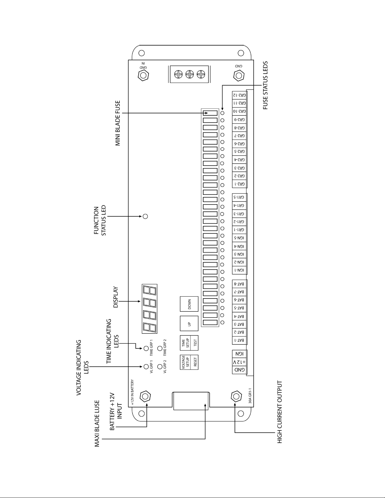
Product Overview
Figure 1: PDU-31SS

212-0024-SS 3July 30th, 2019
Introducon
The PDU-31SS is designed to provide automove emergency and public service vehicle equipment installers
with a solid state, single point power distribuon system for installed electrical devices. The installaon is
fast, reliable and safe. It oers programmable low baery voltage shutdown, programmable med shut-
down, power distribuon and equipment protecon. The PDU-31SS provides a direct, easily traceable route
to the input power source avoiding interfering with the vehicles factory wiring harnesses. All circuits are in-
dividually fused (MAXI fuse for the heavy duty outputs & MINI fuses for the standard outputs) and each out-
put has a FUSE OK LED indicator for ease of troubleshoong.
Features
Programmable Low Baery Voltage Shutdown
Programmable Timed Shutdown
Vehicle Baery Voltage Monitoring
Each output has an LED fuse status indicator
Standby Mode
Timed Shutdown Mode
Test Mode
Reset Mode
31 Outputs
Technical Specicaons
Voltage Range: 11-18 VDC
Maximum Current Load: 10A per output, fused at 15A
30A per heavy duty output, fused at 50A
100A total maximum current per PDU
Stand-by Current: 0A
Programmable Low Voltage Disconnect: Programmable from 11VDC
Factory default set at 11.5VDC (10 second delay)
NOTE: Baery manufacturers recommend to not program low voltage disconnect below 11 VDC
unless the vehicle is equipped with a second baery.
High Voltage disconnect set at 18VDC, (10 second delay)
Programmable mer setup: 1 minute - 99.59 hours.
Fuse Type: MINI fuse for regular outputs.
MAXI fuse for heavy-duty outputs.
Operang Temperature: -40° C to +65° C (-40F to +149F)
Dimensions: L 12” X W 4” X H 1.5”

212-0024-SS 4July 30th, 2019
Warning
1. The use of emergency warning devices does not ensure the safety of the operator. The operator is
responsible to ensure safe operaon of the vehicle regardless of whether the warning device is in
operaon or not
2. The eecveness of this or any warning device is highly dependent on proper installaon and
maintenance. Read the manufactures instrucons before installing and follow all recommenda-
ons.
3. When in use the operator must ensure that the warning signal is visible and not obstructed by vehi-
cle components (i.e. open trunk lid), people or other obstrucons
4. This device is intended for use by authorized personnel only. It is the responsibility of the user to
ensure that all local, state, provincial and federal laws are being complied with. D&R assumes no
liability for any loss resulng from the use of this device.
5. The device must be installed so as not to reduce the output performance of vehicle systems.
6. Placement of control switches must be so as to provide convenient reach for the operator without
loosing eye contact with the road.
7. Emergency warning devices require high electrical voltages and/or currents. Properly connect and
ground all circuits. Shorng or improper grounding of this device may caused personal injuring, ve-
hicle damage and/or device damage.
8. All operators should be properly trained in the operaon of this device to ensure both operator and
public safety
9. Any device used inside a vehicle, may cause severe personal injury if not properly mounted and
secured. Objects used in the vehicle may become airborne during a collision or other sudden chang-
es in vehicle speed or direcon, such as braking, acceleraon or turns.
10. Be sure to mount unit through the steel of the vehicle. Avoid mounng through plasc or other non
-structural materials.
11. POINT OF INSTALLATION MUST NOT INTERFERE WITH DEPLOYMENT OF VEHICLE AIR BAGS.
12. D&R Electronics recommends that this and any of our other products be installed by qualied per-
sonnel.
13. Good wiring pracces and thorough knowledge of vehicle power systems is required by the installer
of this and any other product.
14. Looms, grommets, cable es or other installaon hardware should be used to anchor and protect
wiring.
15. All wire sizes must meet the minimum sizes specied by the manufacturer.
16. Splices should be minimized and made in a fashion so as to protect from moisture which could
cause corrosion thereby reducing conducvity.
17. The exact number of available connecons varies by applicaon. Refer to the specicaons and
typical output fusing combinaons to ensure that the safety and reliability of this product is not
compromised.
Warning
Maintenance
The PDU-31SS does not require user maintenance except for individual fuse replacements.
Do not aempt to open or repair.
Contact your local distributor or D&R Electronics for repair.

212-0024-SS 5July 30th, 2019
Mechanical Installaon
The PDU-31SS may be mounted anywhere inside the vehicle away from heat, moisture or the elements.
NOTE the PDU is not weather ght. Do not mount it in the engine compartment, on the exterior of the ve-
hicle or an area where moisture, dirt or other contaminants can fall into the exposed areas of the PDU. En-
sure that the mounng locaon is at and the device is secured to solid vehicle body parts.
1. Determine an appropriate mounng locaon.
2. Conrm there is adequate access and clearance for the wiring and all connecons.
3. Secure the PDU with 4 self-tapping mounng screws (not supplied).
Electrical Installaon
12V Baery
Using appropriate size wire connect to the posive baery terminal fuse at the baery side with 100A fuse or
a circuit breaker.
Ground
Using appropriate size wire connect to the negave baery terminal or a suitable chassis ground.
Ignion Sense
Connect this terminal to the vehicle ignion switch using 18 gauge wire.
Baery Sense
Connect this terminal directly to the posive of the baery using a 18 gauge wire fused with a 5A fuse.
Ground Sense
Connect this terminal to the negave side of the baery or a suitable chassis ground.
Outputs
The PDU oers the following outputs. (1) 25A in group 1, (5) 10A in group 1, (12) 10A in group 2, (5) in igni-
on and (8) directly from baery (this output is available even when the PDU is dormant).
NOTE: When the IGNITION is OFF and the main +12V power input is disconnected, the DISPLAY will
stay ON unl both mers expire or the BATTERY SENSE input is disconnected.

212-0024-SS 6July 30th, 2019
Figure 2: Wiring
Wiring Diagram

212-0024-SS 7July 30th, 2019
Table 1: Recommended Input Power Feed Wire Size
Max. Total Load
Current Amps
Wire Size (AWG) vs Wire Length (3% drop)
<5 . 5-10 . 10-15 . 15-20 . 25-30 .
25 #10 #6 #6 #4 #2
50 #6 #4 #2 #2 #0
75 #6 #2 #1 #0 #3/0
100 $4 #2 #0 #2/0 #4/0
Table 2: Recommended Circuit Load Wire Size
Max. Total Load
Current Amps
Wire Size (AWG) vs Wire Length (3% drop)
1-5 . 5-10 . 10-15 . 15-20 . 25-30 .
518 18 18 16 14
10 18 16 14 14 12
15 18 14 12 12 10
20 16 14 12 10 8

212-0024-SS 8July 30th, 2019
Modes of Operaon
Standby Mode
In Standby Mode the PDU is dormant with zero consumpon. It awakes either by turning the ignion or by
depressing the test switch. The test switch will turn on all outputs for two minutes and if no other acon is
taken during this me, the PDU will do dormant again.
Low Baery Voltage Shutdown Mode
The PDU provides a baery protecon by turning o the outputs when the voltage reaches a pre-set value.
This seng is the same for both groups.
Timed Shutdown Mode
The PDU allows the user to set the me remaining aer the ignion switch is turned o. This seng is the
same for both groups. The 7 segment display will cycle through and indicate the me remaining for each
output group.
Test Mode
Pressing the TIME SETUP/TEST buon for at least 2 seconds will start a 20 second test mode for both output
groups.
Reset Mode
Pressing the VOLTAGE SETUP/RESET buon for at least 2 seconds will reset the PDU to STANDBY mode.
Vehicle Baery Voltage Monitoring
The vehicle baery voltage is connuously monitored.

212-0024-SS 9July 30th, 2019
Programming the PDU-31SS
NOTE: If no acon is taken within 20 seconds during setup, the PDU will return to Standby Mode.
Low Voltage Shutdown Setup
The PDU-31SS’ factory default LOW VOLTAGE SHUTDOWN value is set to 11.5 VDC for both Group 1 and Group 2 out-
puts. This value can be adjusted by the user for each of the two output groups separately by following these steps:
Tap the VOLTAGE SETUP/RESET buon. The VL GRP1 LED will turn ON and the display will show the current volt-
age set for GROUP 1 outputs. Tap the UP or DOWN buons to enter the new voltage.
Tap the VOLTAGE SETUP/RESET buon. The VL GRP2 LED will turn ON and the display will show the current volt-
age set for GROUP 2 outputs. Tap the UP or DOWN buons to enter the new voltage.
Tap the VOLTAGE SETUP/RESET buon again to save the new values.
Note: - When the vehicle baery voltage drops below the Low Voltage Shutdown values for GROUP 1 or
GROUP 2 outputs, the outputs for that group will be OFF uncondionally.
- The minimum shutdown voltage cannot be set below 11.5VDC unless the vehicle is being ed with
a second baery.
Timed Shutdown Setup
The PDU-31SS factory default shutdown mes are set to:
2 minutes for GROUP 1 outputs
2 hours for GROUP 2 outputs
This value can be adjusted by the user for each of the two output groups separately by following these steps:
Tap the TIME SETUP/TEST buon. The TIME GRP1 LED will turn ON and the display will show the current shut-
down me set for GROUP 1 outputs. Tap the UP or DOWN buons to enter the new me delay.
Tap the TIME SETUP/TEST buon. The TIME GRP2 LED will turn ON and the display will show the current shut-
down me set for GROUP 2 outputs. Tap the UP or DOWN buons to enter the new me delay.
Tap the TIMER SETUP/TEST buon again to save the new values.
Note:
When the vehicle IGNITION switch is turned on, the countdown will be stopped.

212-0024-SS 10 July 30th, 2019
QTY Part Number Descripon
1PDU-31SS PDU-31SS unit w/ 31 out, display, dual programmable mer and voltage
1212-0024-31SS Manual PDU-31SS unit
1Designator sheet for PDU-31SS to record all setup installaon data
Package Contents
NOTE; MINI and MAXI fuses are available for purchase.
Table of contents
Other D&R ELECTRONICS Power Distribution Unit manuals

D&R ELECTRONICS
D&R ELECTRONICS PDU-6SS User manual

D&R ELECTRONICS
D&R ELECTRONICS PDU-16SS User manual

D&R ELECTRONICS
D&R ELECTRONICS PDU14-K User manual

D&R ELECTRONICS
D&R ELECTRONICS PDU42WB User manual

D&R ELECTRONICS
D&R ELECTRONICS PDU42-8S User manual

D&R ELECTRONICS
D&R ELECTRONICS PDU-8S User manual


