manuals.online logo
Brands
  1. Home
  2. •
  3. Brands
  4. •
  5. Danfoss
  6. •
  7. Controllers
  8. •
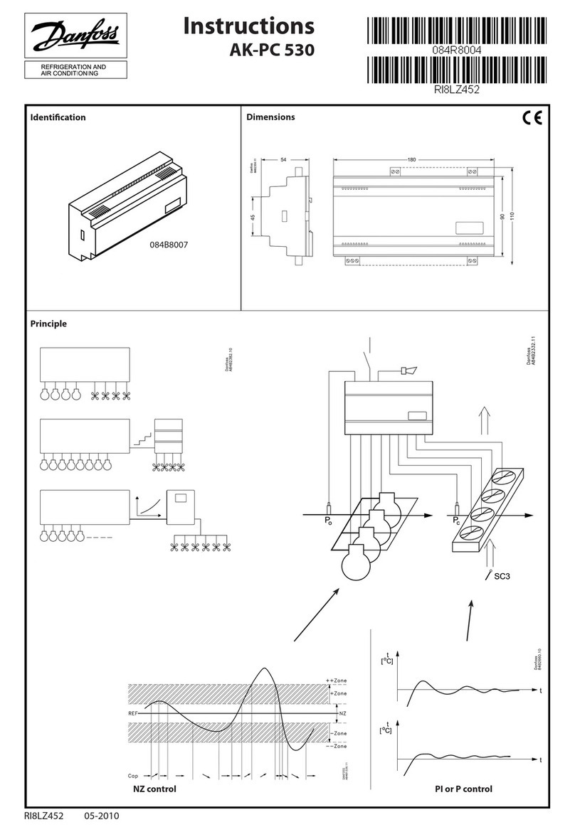
  9. Danfoss PVE 4 Series User manual

Danfoss PVE 4 Series User manual

V310115.A
Installation Guide
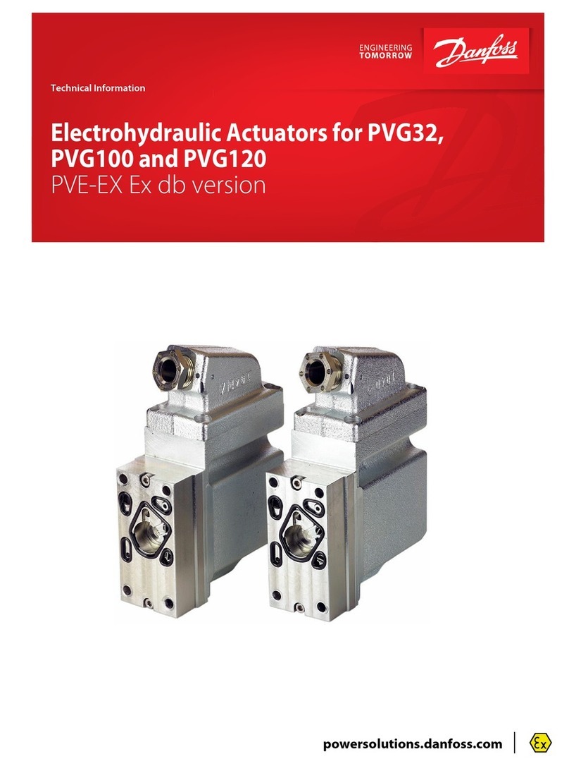
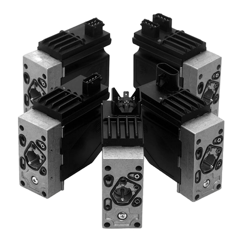
Electrical Actuating Module
PVE series 4 for PVG 32 and PVG 100
© Danfoss, 2014-03 520L0619 • Rev EB • Mar 2014 1
157R9915
157R9915
PVE for PVG 32 and PVG 100:
Oliestrømmens retning for
standard monterede grupper.
Oil ow direction for standard
assembled groups.
Richtung des Ölstroms für
Standard-Baugruppen.
Sens du débit pour ensembles
standard.
Mounting PVE
Instruktionen dækker
Instruction covers
Anleitung umfasst
l'instruction couvre
Danfoss actuators PVEA, PVEH, PVEM, PVEO, PVEP,
PVES, PVEU Variants -R, -DI, -SP, -F.
Connectors Deutsch, AMP, DIN/Hirschmann.
For full documentation see Technical Information, PVE
Series 4 for PVG 32, PVG 100 and PVG 120, 520L0553 on
www. Danfoss.com
V310348A
• Protect LVDT-pin if present
• Ensure O-rings are in place
• Ensure gasket when using AMP and DIN/Hirschmann connector
• Do not over torque
WWarning
PVEA is not for use on PVG 100.
5 [0.2]
157-743.10B
8 ±0.5 N•m
[70 ±4.4 lbf•in]
to tank
to application
P→A
For Technical Information, see Danfoss.com.
2 520L0619 • Rev EB • Mar 2014 © Danfoss, 2014-03
DI general note
Til DI udførelserne er det nødvendigt at have 2 UDC-tilslutninger (UDC og UDC2):
• UDC forsyner elektronikken og
• UDC2 forsyner magnetventilerne
De to jordforbundne stikben er internt forbundet.
Der kan med fordel anvendes to separate strømforsyninger (jvf. tekniske informationer for PVE serie 4)
On DI versions two UDC connections (UDC and UDC2) are necessary.
• UDC will supply the electronics and
• UDC2 will supply the solenoid valves
The two ground pins are internally connected.
With advantages two separate power supplies can be used, see also Technical information for PVE series 4.
Die DI Ausführungen fordern zwei UDC-Anschlüsse (UDC und UDC2):
• UDC versorgt die Elektronik und
• UDC2 versorgt die Magnetventile
De zwei Erdungsstecker sind intern verbunden.
Es kann mit Vorteil zwei separate Stromversorgungen verwendet werden (vgl. technische Informationen
für PVE Serie 4)
Pour les versions DI deux raccordements UDC (UDC et UDC2) sont nécessaires.
• UDC alimente l’électronique
• UDC2 alimente les électrodistributeurs
Les deux bornes masse sont reliées intéreurement.
L’emploi de deux sources d’alimentation séparées a des avantages, voir Information Technique pour PVE
série 4
Version ON/OFF Connection PVEO with direction indication (DI)
Connector 1 A UDC B UDC Gnd Gnd
AMP (grey) p 1 p 2 p 3 p 4
Connector 2 DI-B DI-A Gnd UDC 2
AMP (black) p 1 p 2 p 3 p 4
Connection PVEO standard
Connector A B
AMP/Hirschmann/DIN pin 1 pin 2
Deutsch pin 1 pin 4
Function A (pin 1) B (pin 2)
Neutral 0 0
Q: P →A UDC 0
Q: P →B 0 UDC
Control all PVEO
Connector A B
AMP
Hirschmann/DIN pin 1 pin 2
Deutsch pin 1 pin 4
yGround pins are internally
connected.
yPin 3 is not connected on
Hirschmann/DIN version of
PVEO.
yUDC2 supplies electronics for
feedback signal on PVEO-DI.
AMP version of PVEO/PVEO–R
AMP version of PVEO–DI
Hirschmann/DIN version of PVEO / PVEO–R
Deutsch version of PVEO /PVEO-R
A UDC B UDC
PVEO/PVEO-R
157-502.11
DC
DC
U
U
3
1
2
A UDC
B UDC
A UDC
B UDC
P301 104
Black connector
Grey connector
DI-B
DI-A
PVEO-DI
1
2
4
3
Pin no.
LED
UDC
U
UDC2
DC
A UDC
B UDC
All PVE variants. PVEO and PVEO-R are without LVDT
© Danfoss, 2014-03 520L0619 • Rev EB • Mar 2014 3
Proportional
Version
Standard PVE
Connection PVEA/PVEH/PVEM/PVES/PVEU - also with
oat B four pin
Connector USUDC Gnd Error
AMP pin 1 pin 2 pin 3 pin 4
Hirschmann/
DIN pin 2 pin 1 gnd pin 3
Deutsch pin 1 pin 4 pin 3 pin 2
yOn PVEM the error pin is not used and not connected
(pin 3 Hirschmann/DIN).
yGround pins are internally connected.
Control (US) for standard mounted
PVEA/ PVEH/ PVEM/ PVES
Function Voltage relative PWM
Neutral 0,5 • UDC 50%
Q: P →A 0,5 →0,25 • UDC 50% →25%
Q: P →B 0,5 →0,75 • UDC 50% →75%
Control (US) for standard mounted PVEU
Function PVEU
Neutral 5 V
Q: P →A 5 V →2,5 V
Q: P →B 5 V →7,5 V
Control (US) for standard mounted PVEH/PVEM
oat B four pin version
Function Voltage relative PWM
Neutral 0,5 • UDC 50%
Q: P →A 0,5 →0,34 • UDC 50% →34%
Q: P →B 0,5 →0,65 • UDC 50% →65%
Float 0,75 • UDC 75%
Standard PVE with DI
Connection PVE with direction indication (DI)
Connector 1 USUDC 1 Gnd Error
AMP (grey) p 1 p 2 p 3 p 4
Deutsch p 1 p 4 p 3 p 2
Connector 2 DI-B DI-A Gnd UDC 2
AMP (black) p 1 p 2 p 3 p 4
Deutsch p 4 p 3 p 2 p 1
Control (US) for standard mounted PVEA–DI/ PVEH–DI
Function USPWM
Neutral 0,5 • UDC 50%
Q: P →A 0,5 →0,25 • UDC 50% →25%
Q: P →B 0,5 →0,75 • UDC 50% →75%
yGround pins are internally connected.
yUDC2 only supplies electronics for feedback signal and
error pin on PVEA-DI / PVEH-DI. Two separate power
sources can be used.
LED
AMP version PVEA/PVEH/PVES/PVEU
Deutsch version PVEA/PVEH/PVES/PVEU/
PVEH oat B
Hirschmann/DIN version PVEH/PVEM/PVES/
PVEH oat B/PVEM oat B
Black connector
Grey connector
DI-B
DI-A
PVEA-DI/PVEH-DI
1
2
4
3
Pin no.
LED
UDC1
S
U
Error UDC2
AMP version PVEA–DI/PVEH–DI
P301 105
2
1
Error 3
4
US
UDC UDC2
DI-B
DI-A
2
1
3
4
PVEA-DI/PVEH-DI
LED
Deutsch version PVEA–DI/PVEH–DI
4 520L0619 • Rev EB • Mar 2014 © Danfoss, 2014-03
Not
connec
ted
Error
Us
3
2
1
4
5
6
Spool position
PVES-SP
UDC
LED
Proportional
Version
Deutsch version PVES–SP
LED
Float
Not con-
nected
Error
157-779
Fl
oat
Error
Us
3
2
1
4
5
6
No con-
nection
PVEH-F
UDC
LED
PVE with separate Float pin
Connection PVEH with oat A six pin
Connector US(control) UDC (power) Float Ground Error
AMP pin 1 pin 2 pin 5 pin 3 pin 4
Deutsch pin 1 pin 6 pin 3 pin 5 pin 2
AMP with separate oat pin
Deutsch version with separate oat pin
Control (US) for standard mounted PVEH/PVEM oat A six
pin version
Function Voltage relative PWM
Neutral 0,5 • UDC 50%
Q: P →A 0,5 →0,25 • UDC 50% →25%
Q: P →B 0,5 →0,75 • UDC 50% →75%
Float UDC on Float pin
PWM controled PVE – PVEP
Connection PVEP
Connector PWM A Error PWM B Gnd UDC
Deutsch p 1 p 2 p 3 p 5 p 6
Control (US) for standard mounted PVEP
Function PWM A PWM B
Neutral < 10% < 10%
Q: P →A 10% →80% < 10%
Q: P →B < 10% 10% →80%
Deutsch version with PVEP
LED
Standard PVE with SP
Connection PVE with Spool Position (SP)
Connector USError SP Gnd UDC
Deutsch p 1 p 2 p 4 p 5 p 6
Control (US) for standard mounted PVES-SP
Function USPWM
Neutral 0,5 • UDC 50%
Q: P →A 0,5 →0,25 • UDC 50% →25%
Q: P →B 0,5 →0,75 • UDC 50% →75%
© Danfoss, 2014-03 520L0619 • Rev EB • Mar 2014 5
Safety and Monitoring
The –SP functionality is a 0,5V to 4,5V inverted feedback with 2,5V as neutral value.
Spool Position Feedback
(-SP)
Spool travelSpool travel
0.5V
7 mm
100%
B port
7 mm
100%
A port
0 mm
Neutral
2.5V
4.5V
Usp
Us
Us
Us
Usp
Usp
25% UDC
50% UDC
75% UDC
Fault monitoring overview
Type Fault
monitoring
Delay before
error out
Error mode
Error
output
status
Fault
output on
PVE 1)
LED light
Memory
(reset
needed)
PVEO
PVEM No fault
monitoring - - - - - -
PVEA
PVEH
PVEP
PVES
PVEU
Active 500 ms
(PVEA: 750 ms)
No fault Low < 2 V Green -
Input signal faults
High ∼UDC
Flashing red
YesTransducer (LVDT)
Constant red
Close loop fault
Passive 250 ms
(PVEA: 750 ms)
No fault Low < 2 V Green -
Input signal faults
High ~UDC
Flashing red
NoTransducer (LVDT)
Constant red
Close loop fault
PVE
Float
six pin Active
500 ms Float not active
High ~UDC
Constant red
Yes
750 ms Float still active
1) Measured between fault output pin and ground.
Direction Indication
Feedback (-DI)
As shown in the gure, both “DI-A” and “DI-B” signals are “High” when the spool is inneutral
position. When the spool is moving in the A direction, the “DI-A” signal goes “Low” and the “DI-B”
signal stays “High”. The reverse is true when the spool is moved in the B direction.
Direction Indication Feedback (-DI)
DI-A low
DI-B high
DI-A high
DI-B low
Spool position‘x’
mm [in]
B-port
PVBS away from PVE
A-port
PVBS towards PVE
0.4 0.8-0.8 -0.4 0
Both direction indication signals go low when the error indicator goes high.
Values for both Direction Indicators, pin A and pin B
Transition to low from high 0.8 ± 0.1 mm [0.031 in]
Transition to high from low 0.4 ± 0.1 mm [0.015 in]
Transition to low both pins error pin goes high
Maximum load of “DI-A” , “DI-B” 50 mA
Voltage UDC high by load 20 mA > UDC –1.5 V
Voltage UDC high by load 50 mA > UDC –2.0 V
Voltage low < 0.2 V
6 520L0619 • Rev EB • Mar 2014 © Danfoss, 2014-03
Følgende tekniske data bygger på typiske testresultater. Der anvendes mineralsk olie med en viskositet på
21 mm2/s [102 SUS] og en temperatur på 50°C [122°F].
The following technical data are from typical test results. For the hydraulic system a mineral based
hydraulic oil with a viscosity of 21 mm2/s [102 SUS] and a temperature of 50°C [122°F] were used.
Folgende technische Daten bauen auf typische Testergebnisse. Es wurde Mineralöl mit einer Viskosität
von 21 mm2/s [102 SUS] und einer Temperatur von 50°C [122°F] verwendet.
Les caractéristiques techniques suivantes sont tirées de résultats de tests typiques. Pour le système
hydrau
lique, on a utilisé une huile minérale d’une viscosité de 21
mm2
/s [102 SUS] et à une température
de
50°C [122°F]
.
PVEO, PVEM
Supply voltage UDC
rated 12 V DC 24 V DC
range 11 V to 15 V 22 V to 30 V
max. ripple 5%
Current consumption at rated voltage 0.65 A @ 12 V 0.33 A @ 24 V
Signal voltage (PVEM) neutral 0.5 x UDC
A-port ↔ B-port 0.25 • UDC to 0.75 • UDC
Signal current at rated voltage (PVEM) 0.25 mA 0.50 mA
Input impedance in relation to 0.5 • UDC 12 KΩ
Power consumption 8 W
PVEA, PVEH, PVEP, PVES, PVEU
Supply voltage UDC rated / range 11 V to 32 V
max. ripple 5%
Current consumption
at rated voltage PVEH/PVEP/PVES/PVEU (PVEA) 0.57 (0.28) A @ 12 V 0.3 (0.15) A @ 24 V
Signal voltage
PVEA/PVEH/PVES - neutral 0.5 x UDC
PVEA/PVEH/PVES - A-port ↔ B-port 0.25 • UDC to 0.75 • UDC
PVEU - neutral 5V
PVEU - A-port ↔ B-port 2.5V to 7.5V
PVEP - neutral A< 10%, B < 10%
PVEP - A-port 10%<A<80%, B< 10%
PVEP - B-port A< 10%, 10%<B<80%
Signal current at rated voltage 0.25 mA to 0.70 mA
Input impedance in relation to 0.5 • UDC 12 KΩ
Input capacitor 100 ηF
Power consumption PVEH/PVEP/PVES/PVEU (PVEA) 7 (3.5) W
Oil viscosity
Oil
viscosity
range 12
–
75 mm
2
/s
[65
–
347 SUS]
min. 4 mm
2
/s [39 SUS]
max. 460 mm
2
/s [2128 SUS]
Bemærk: Maksimum opstartsviskositet
Note: Max. start up viscosity 2500 mm2/s
Beachte: Maximale Viskosität bei Inbetriebnahme
Remarque : Viscosité maximale au démarrage 2500 mm2/s
Filtering in the hydraulic system
Required
operating
cleanliness level
18/16/13
(ISO 4406, 1999 version)
Oil temperature
Oil
temperature
range 30 – 60˚C [86 – 140˚F]
min. -30˚C [-22˚F]
max. 90˚C [194˚F]
Operating temperature
Ambient -30 – 60˚C [-22 – 140˚F]
Stock -40 – 90˚C [-40 – 194˚F]
Recommended long
time storage in
packaging
10 – 30˚C [50 – 86˚F]
Pilot pressure
Pilot pressure
(relative to T
pressure)
nom. 13.5 bar [196 psi]
min. 10 bar [145 psi]
max. 15 bar [217 psi]
Grade of enclosure*
Connector version
AMP JPT IP 66
Hirschmann IP 65
Deutsch IP 67
* According to the international standard IEC 529.
Technical data
Bemærk: I særligt udsatte maskiner anbefales der beskyttelse med en skærm.
Beachte: In besonders ausgesetzten Maschinen wird Schutz in Form von
elektrischer Abschirmung empfohlen.
NB: In particularly exposed applications, protection by screen is recommended.
Remarque: Pour les applications particulièrement exposées, il est recommandé
d’installer une protection par écran.
© Danfoss, 2014-03 520L0619 • Rev EB • Mar 2014 7
WWarning
Alle mærker og typer af retningsventiler – også proportional ventiler – kan svigte og forårsage alvorlig skade. Det er derfor vigtigt at analysere
maskinen i alle enkeltheder.
Da proportionalventiler anvendes under mange forskellige driftsbetingelser og i mange forskellige maskiner, er det alene maskinproducentens
ansvar at træe det endelige produktvalg og sikre at samtlige maskinens krav til ydelse, sikkerhed og advarsler er opfyldt.
Ved valg af reguleringssystem – og sikkerhedsniveau – kan man f.eks. støtte sig til EN954-1 (sikkerhedsrelaterede bestanddele i
reguleringssystemet.)
Alle Fabrikate und Typen von Wegeventilen – einschließlich Proportionalventile – können versagen und schlimme Unfälle verursachen. Es ist
daher wichtig, die Anwendung in allen Details zu analysieren.
Weil Proportionalventile unter vielen unterschiedlichen Arbeitsbedingungen und in vielen verschiedenen Anwendungen benutzt werden, trägt
allein der Maschinenhersteller die Verantwortung für seine endgültige Wahl von Produkt, und er ist ebenfalls dafür verantwortlich, dass alle
Leistungs-, Sicherheits- und Warnungsanforderungen an seine Maschine erfüllt sind.
Zur Wahl vom Reglersystem und Sicherheitsniveau kann man sich z.B. auf EN954-1 stützen.
All marks and brands of valves – inclusive proportional valves – can fail and cause serious damage. It is therefore important to analyse all aspects
of the application.
Because the proportional valves are used in many dierent operation conditions and applications, the manufacturer of the application is alone
responsible for making the nal selection of the products – and assuring that all performance, safety and warning requirements of the
application are met.
The process of choosing the control system – and safety level – could e.g. be governed by EN 954-1 (Safety related parts of control system). See
also Technical information for PVE series 4.
Tous les distributeurs - y compris les distributeurs proportionnels - peuvent tomber en panne et entraîner de sérieux dommages. C’est la raison
pour laquelle il est important d’analyser chaque aspect de l’application. Les vannes proportionnelles étant utilisées dans de nombreuses
conditions d’exploitation et applications diérentes, le fabricant de l’application porte l’entière responsabilité de la sélection nale des produits
et du respect des exigences en matière de rendement, de sécurité et d’avertissement. Le choix du système de commande – et du niveau de
sécurité – peut être fait par exemple sur la base de la norme EN 954-1 (parties du système de commande relatives à la sécurité). Se reporter
également à Information technique pour PVE série 4.
Udluftning
Hvis gruppen er monteret vertikalt, anbefales det at udlufte ved
justerskruer (Pos.A)
Bemærk: Ved PVEA kan det, pga.dens hydrauliske opbygning, være
påkrævet at foretage udluftning.
Bleeding
If the group is installed vertically, it is recommended to bleed it at the
adjusting screws (Pos.A)
Note: Because of the hydraulic build-up of PVEA, it may be necessary to
bleed the PVEK.
Entlüftung
Wenn die Gruppe vertikal montiert ist, empfehlen wir an den
Justierschrauben zu entlüften (Pos.A)
Beachte: Wegen des hydraulischen Aufbaus von PVEA kann eine Entlüftung
erforderlich sein.
Purge
Si l'ensemble est monté verticalement, il est recommandé de le purger au
moyen des vis d'ajustage (Pos.A)
Nb! En raison du système hydraulique des PVEAs il peut s'avérer nécessaire
de purger.
LS
T P
A
V310109.A
100*[4]
170[6.69]
Beskyttelse
Alle PVE-moduler overholder tæthedsgrad IP65 i henhold til
IEC 529. Det anbefales dog, at PVE’en på særligt udsatte steder
beskyttes i form af en afskærmning eller lignende.
Schutzart
Alle PVE-Module erfüllen die Schutzart IP65 gemäß IEC 529.
Es ist jedoch empfehlenswert, der PVE in besonders
ausgesetzten Einsatzbereichen mit einer Abschirmung oder
dergleichen zu schützen.
Protection
All PVE modules comply with protection class IP65 in
accordance with IEC 529. However, in particularly exposed
applications protection in the form of screening is
recommended.
Protection
Tous les modules PVE possèdent le degré de protection IP65
conformément à la IEC 529. Dans les zones particulièrement
exposées, il est cependant conseillé de protéger le PVE à l’aide
d’un écran ou d’un dispositif similaire.
8 520L0619 • Rev EB • Mar 2014 © Danfoss, 2014-03
Accessories
Cables code numbers
Feature Wire colors Length Code number
Connector pin 1 pin 2 pin 3 pin 4 pin 5 pin 6
Deutsch 4 pin white blue yellow red — — 4 m 11007498
6 pin white blue yellow red black green 4 m 11007513
AMP 4 pin white blue yellow red — — 4 m 157B4994
6 pin white red black yellow green blue 5 m 157B4974
AMP/black coding 4 pin white blue yellow red — — 4 m 157B4995
Connector code numbers
Part number Name
157B4992 AMP CONNECTING KIT (GREY) 4 pin with housing, contact and wire sealing
157B4993 AMP CONNECTING KIT (BLACK) 4 pin with housing, contact and wire sealing
984L3165 EL-PLUG, ON-OFF black Hirschmann DIN connector set*
Set of seals code numbers
Part number Name Actuator
157B4997 Set of seals PVE for PVG 32/ PVG 100
155G8519 Set of seals PVE for PVG 120
11061235 Set of seals PVHC for PVG 32/ PVG 100

Other manuals for PVE 4 Series

1

This manual suits for next models

28

Other Danfoss Controllers manuals

Danfoss AK-CC55 User manual

Danfoss

Danfoss AK-CC55 User manual

Danfoss ThermoControl-3 Installation instructions manual

Danfoss

Danfoss ThermoControl-3 Installation instructions manual

Danfoss EKC 316A User manual

Danfoss

Danfoss EKC 316A User manual

Danfoss VLT 5000 User manual

Danfoss

Danfoss VLT 5000 User manual

Danfoss AK-CC 460 User manual

Danfoss

Danfoss AK-CC 460 User manual

Danfoss AK-CC55 User manual

Danfoss

Danfoss AK-CC55 User manual

Danfoss VTL MCD 203 Series User manual

Danfoss

Danfoss VTL MCD 203 Series User manual

Danfoss MCO 305 User manual

Danfoss

Danfoss MCO 305 User manual

Danfoss VLT Center Winder MCO 352 User manual

Danfoss

Danfoss VLT Center Winder MCO 352 User manual

Danfoss Old ICAD 600 series User manual

Danfoss

Danfoss Old ICAD 600 series User manual

Danfoss EKC 326A User manual

Danfoss

Danfoss EKC 326A User manual

Danfoss Icon Master User manual

Danfoss

Danfoss Icon Master User manual

Danfoss AVQM Series User manual

Danfoss

Danfoss AVQM Series User manual

Danfoss AME 35 User manual

Danfoss

Danfoss AME 35 User manual

Danfoss ERC 113 User manual

Danfoss

Danfoss ERC 113 User manual

Danfoss PMFH Series User manual

Danfoss

Danfoss PMFH Series User manual

Danfoss AME 13 SU-1 User manual

Danfoss

Danfoss AME 13 SU-1 User manual

Danfoss EKC 315A User manual

Danfoss

Danfoss EKC 315A User manual

Danfoss ECL Comfort 301 User manual

Danfoss

Danfoss ECL Comfort 301 User manual

Danfoss AK-CC 750A User manual

Danfoss

Danfoss AK-CC 750A User manual

Danfoss AME 110 User manual

Danfoss

Danfoss AME 110 User manual

Danfoss VLT Soft Starter MCD 600 User manual

Danfoss

Danfoss VLT Soft Starter MCD 600 User manual

Danfoss MCI 15BP User manual

Danfoss

Danfoss MCI 15BP User manual

Danfoss TWA-Z User manual

Danfoss

Danfoss TWA-Z User manual

Popular Controllers manuals by other brands

Lab.gruppen LAB.LEVEL4 quick start guide

Lab.gruppen

Lab.gruppen LAB.LEVEL4 quick start guide

fadini Elpro 37DS manual

fadini

fadini Elpro 37DS manual

Linear Technology DC2268A-1 Demo Manual

Linear Technology

Linear Technology DC2268A-1 Demo Manual

Johnson Controls FEC16 Series installation instructions

Johnson Controls

Johnson Controls FEC16 Series installation instructions

TMK IGNIS Alfa manual

TMK

TMK IGNIS Alfa manual

ST STM32W-SK user manual

ST

ST STM32W-SK user manual

Evco EV3143 quick start guide

Evco

Evco EV3143 quick start guide

Chauvet Professional RDM2go Quick reference guide

Chauvet Professional

Chauvet Professional RDM2go Quick reference guide

Koso REXA Electraulic Xpac Installation and operation manual

Koso

Koso REXA Electraulic Xpac Installation and operation manual

Siro 40567 instruction manual

Siro

Siro 40567 instruction manual

AG-NAV AgNav Platinum Operation manual

AG-NAV

AG-NAV AgNav Platinum Operation manual

Paxton Switch2 How to program

Paxton

Paxton Switch2 How to program

DH Instruments OPG1-30000-AF Operation and maintenance manual

DH Instruments

DH Instruments OPG1-30000-AF Operation and maintenance manual

Omnio APG03B-RS485 manual

Omnio

Omnio APG03B-RS485 manual

Netafim NMC-64 User & installation manual

Netafim

Netafim NMC-64 User & installation manual

Ko Propo BSx2 Series manual

Ko Propo

Ko Propo BSx2 Series manual

Johnson Controls FAC2611 installation guide

Johnson Controls

Johnson Controls FAC2611 installation guide

Bodyfriend LBF-R700 manual

Bodyfriend

Bodyfriend LBF-R700 manual

manuals.online logo
manuals.online logoBrands
  • About & Mission
  • Contact us
  • Privacy Policy
  • Terms and Conditions

Copyright 2025 Manuals.Online. All Rights Reserved.