manuals.online logo
Brands
  1. Home
  2. •
  3. Brands
  4. •
  5. Danfoss
  6. •
  7. Controllers
  8. •
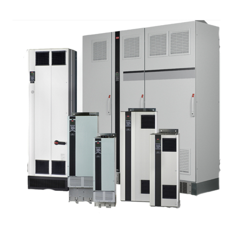
  9. Danfoss VLT HVAC Drive FC 102 User manual
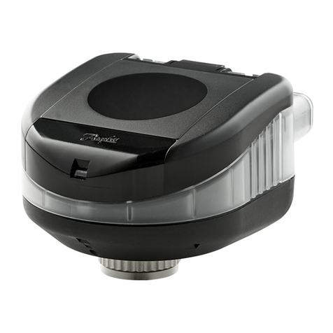
Danfoss VLT HVAC Drive FC 102 User manual

1.1 Introduction
The instructions provide information about the replacement of
internal mains fuses for single-phase and 3-phase drives in A,
B, and C enclosures. This kit is designed and tested for the
North American market.
A2 A3 A5 B1 B2 C1 C2
Single-phase ——XXXXX
3-phase XXXXXXX
Table 1.1 Supported Enclosures
1.2 Safety Instructions
WARNING
DISCHARGE TIME
The drive contains DC-link capacitors, which can remain
charged even when the drive is not powered. High voltage
can be present even when the warning LED indicator lights
are o. Failure to wait the specied time after power has
been removed before performing service or repair work can
result in death or serious injury.
•
Stop the motor.
•
Disconnect AC mains and remote DC-link power
supplies, including battery back-ups, UPS, and DC-
link connections to other drives.
•
Disconnect or lock PM motor.
•
Wait for the capacitors to discharge fully. The
minimum waiting time is specied in Ta bl e 1 .2 and
Tabl e 1. 3, and is also visible on the nameplate on
top of the drive.
•
Before performing any service or repair work, use
an appropriate voltage measuring device to make
sure that the capacitors are fully discharged.
Voltage [V] Power range [kW (hp)] Minimum waiting
time (minutes)
208–230 0.25–3.7 kW (0.3–5 hp) 4
5.5–45 kW (7.5–60 hp) 15
460–480 0.25–7.5 kW (0.3–10 hp) 4
11–90 kW (15–125 hp) 15
575–600 0.75–7.5 kW (1.0–10 hp) 4
11–90 kW (15–125 hp) 15
Table 1.2 Discharge Time for VLT
®
HVAC Drive FC 102,
VLT
®
Refrigeration Drive FC 103, and VLT
®
AQUA Drive FC 202
Voltage [V] Power range [kW (hp)] Minimum waiting
time (minutes)
208–230 0.25–3.7 kW (0.3–5 hp) 4
5.5–37 kW (7.5–50 hp) 15
460–480 0.25–7.5 kW (0.3–10 hp) 4
11–75 kW (15–100 hp) 15
575–600 0.75–7.5 kW (1–10 hp) 4
11–75 kW (15–100 hp) 15
Table 1.3 Discharge Time for VLT
®
AutomationDrive FC 300
1.3 Fuse/Relay Locations
Enclosure size A
Illustration 1.1 and Illustration 1.2 show the mains, motor, and
relay connection locations for A2, A3, and A5 enclosures.
Illustration 1.2 identies the fuse locations.
1 Input/mains connection
2 Relay connection
3 Motor connection
Illustration 1.1 A2 and A3 Enclosures (3-phase Only)
Installation Instructions
Internal Mains Fuse Replacement for VLT®Drives,
0.25–90 kW (0.3–125 hp)
FC 102/FC 103/FC 202/FC 301/FC 302
Danfoss A/S © 10/2018 All rights reserved. MI92D402
1 Relay connection
2Fuses
3 Motor connection
4 Input/mains connection
Illustration 1.2 A5 Enclosure (Single-phase and 3-phase)
Enclosure size B
Illustration 1.3, Illustration 1.4, and Illustration 1.5 show the
mains, motor, and relay connection locations for B1 and B2
enclosures.
Motor and relay connections are located under the fuse block
plate. To access these connectors, remove the 3 T20 screws
that are securing the fuse block plate to the drive and lift o
the plate. Do not disassemble the fuse block plate.
1 Input/mains connection
2 Fuse block plate
3 Motor connection (beneath the fuse block plate)
4 Relay connection (beneath the fuse block plate)
Illustration 1.3 B1 Enclosure (Single-phase and 3-phase)
Installation Instructions Internal Mains Fuse Replacement for VLT
®
Drives, 0.25–90 kW (0.3–125 hp)
FC 102/FC 103/FC 202/FC 301/FC 302
2
Danfoss A/S © 10/2018 All rights reserved. MI92D402
1 Fuse block plate
2 Input/mains connection
3 Relay connection (beneath the mains fuse block)
4 Motor connection (beneath the mains fuse block)
Illustration 1.4 B2 Enclosure (Single-phase)
1 Fuse block plate
2 Input/mains connection
3 Relay connection (beneath the fuse block plate)
4 Motor connection (beneath the mains fuse block)
Illustration 1.5 B2 Enclosure (3-phase)
Installation Instructions Internal Mains Fuse Replacement for VLT
®
Drives, 0.25–90 kW (0.3–125 hp)
FC 102/FC 103/FC 202/FC 301/FC 302
MI92D402 Danfoss A/S © 10/2018 All rights reserved.
3
Enclosure size C
Illustration 1.6 and Illustration 1.7 show the mains, motor, and
relay connection locations for C1 and C2 enclosures.
1 Input/mains connection
2 Relay connection
3Fuses
4 Motor connection
Illustration 1.6 C1 Enclosure
1 Input/mains connection
2 Relay connection
3Fuses
4 Motor connection
Illustration 1.7 C2 Enclosure
Installation Instructions Internal Mains Fuse Replacement for VLT
®
Drives, 0.25–90 kW (0.3–125 hp)
FC 102/FC 103/FC 202/FC 301/FC 302
4
Danfoss A/S © 10/2018 All rights reserved. MI92D402
1.4 Mains Voltage Ratings
Single-phase drives
FC 102/FC 103 FC 202 FC 301/FC 302 [NO] FC 301/FC 302 [HO]
[V] kW (hp) kW (hp) kW (hp) kW (hp)
208–230 1.1 (1.5) 1.1 (1.5) — —
460–480 — — — —
575–600 — — — —
Table 1.4 A5 Enclosure (Single-phase)
FC 102/FC 103 FC 202 FC 301/FC 302 [NO] FC 301/FC 302 [HO]
[V] kW (hp) kW (hp) kW (hp) kW (hp)
208–230 1.5–5.5 (2–7.5) 1.5–5.5 (2–7.5) — —
460–480 — — — —
575–600 — — — —
Table 1.5 B1 Enclosure (Single-phase)
FC 102/FC 103 FC 202 FC 301/FC 302 [NO] FC 301/FC 302 [HO]
[V] kW (hp) kW (hp) kW (hp) kW (hp)
208–230 7.5 (10) 7.5 (10) — —
460–480 — — — —
575–600 — — — —
Table 1.6 B2 Enclosure (Single-phase)
FC 102/FC 103 FC 202 FC 301/FC 302 [NO] FC 301/FC 302 [HO]
[V] kW (hp) kW (hp) kW (hp) kW (hp)
208–230 15 (20) 15 (20) — —
460–480 — — — —
575–600 — — — —
Table 1.7 C1 Enclosure (Single-phase)
FC 102/FC 103 FC 202 FC 301/FC 302 [NO] FC 301/FC 302 [HO]
[V] kW (hp) kW (hp) kW (hp) kW (hp)
208–230 22 (30) 22 (30) — —
460–480 — — — —
575–600 — — — —
Table 1.8 C2 Enclosure (Single-phase)
Installation Instructions Internal Mains Fuse Replacement for VLT
®
Drives, 0.25–90 kW (0.3–125 hp)
FC 102/FC 103/FC 202/FC 301/FC 302
MI92D402 Danfoss A/S © 10/2018 All rights reserved.
5
3-phase drives
FC 102/FC 103 FC 202 FC 301/FC 302 [NO] FC 301/FC 302 [HO]
[V] kW (hp) kW (hp) kW (hp) kW (hp)
208–230 1.1–3.7 (1.5–5) 0.25–3.7 (0.3–5) — 0.25–3.7 (0.34–5)
460–480 1.1–7.5 (1.5–10) 0.37–7.5 (0.5–10) — 0.37–7.5 (0.5–10)
575–600 1.1–7.5 (1.5–10) 0.75–7.5 (1–10) — 0.75–7.5 (1–10)
Table 1.9 A2//A3/A5 Enclosures (3-phase)
FC 102/FC 103 FC 202 FC 301/FC 302 [NO] FC 301/FC 302 [HO]
[V] kW (hp) kW (hp) kW (hp) kW (hp)
208–230 5.5–11 (7.5–15) 5.5–11 (7.5–15) 7.5–11 (10–15) 5.5–7.5 (7.5–10)
460–480 11–18.5 (15–25) 11–18.5 (15–25) 15–18 (20–25) 11–15 (15–20)
575–600 11–18.5 (15–25) 11–18.5 (15–25) 11–18 (15–25) 11–15 (15–20)
Table 1.10 B1 Enclosure (3-phase)
FC 102/FC 103 FC 202 FC 301/FC 302 [NO] FC 301/FC 302 [HO]
[V] kW (hp) kW (hp) kW (hp) kW (hp)
208–230 15 (20) 15 (20) 15 (20) 11 (15)
460–480 22–30 (30–40) 22–30 (30–40) 22–30 (30–40) 18.5–22 (25–30)
575–600 22–30 (30–40) 22–30 (30–40) 22–30 (30–40) 18.5–22 (25–30)
Table 1.11 B2 Enclosure (3-phase)
FC 102/FC 103 FC 202 FC 301/FC 302 [NO] FC 301/FC 302 [HO]
[V] kW (hp) kW (hp) kW (hp) kW (hp)
208–230 18.5–30 (25–40) 18.5–30 (25–40) 18.5–22 (25–30) 15–22 (20–30)
460–480 37–55 (50–75) 37–55 (50–75) 37–55 (50–75) 30–45 (40–60)
575–600 37–55 (50–75) 37–55 (50–75) 37–55 (50–75) 30–45 (40–60)
Table 1.12 C1 Enclosure (3-phase)
FC 102/FC 103 FC 202 FC 301/FC 302 [NO] FC 301/FC 302 [HO]
[V] kW (hp) kW (hp) kW (hp) kW (hp)
208–230 37–45 (50–60) 37–45 (50–60) 30–45 (40–60) 30–37 (40–50)
460–480 75–90 (100–125) 75–90 (100–125) 75–90 (100–125) 55–75 (75–100)
575–600 75–90 (100–125) 75–90 (100–125) 75–90 (100–125) 55–75 (75–100)
Table 1.13 C2 Enclosure (3-phase)
Installation Instructions Internal Mains Fuse Replacement for VLT
®
Drives, 0.25–90 kW (0.3–125 hp)
FC 102/FC 103/FC 202/FC 301/FC 302
6
Danfoss A/S © 10/2018 All rights reserved. MI92D402
1.5 Mains Fuse Replacement Table
Single-phase drives
To replace the same type of mains fuse installed in the unit, refer to Tabl e 1 .1 4. For a list of maximum mains fuse sizes that can be
installed in the unit, or for hp/kW sizes not shown in this chart, refer to the operating guide.
Unit rating FC 102/FC 103/FC 202 FC 301/FC 302
[kW] [hp] 208–230 V 460–480 V 575–600 V 208–230 V 460–480 V 575–600 V
0.37 0.5 — — — — — —
0.55 0.75 — — — — — —
0.75 1 — — — — — —
1.1 1.5 LP-CC-15 15 A, 600 V, Class CC — — — — —
1.5 2 JJN-20 20 A, 300 V, Class T — — — — —
2.2 3 JJN-30 30 A, 300 V, Class T — — — — —
3 4 JJN-35 35 A, 300 V, Class T — — — — —
3.7/4 5 JJN-50 50 A, 300 V, Class T — — — — —
5.5 7.5 JJN-60 60 A, 300 V, Class T — — — — —
7.5 10 JJN-80 80 A, 300 V, Class T — — — — —
11 15 — — — — — —
15 20 FWX-150 150 A, 250 V — — — — —
18.5 25 — — — — — —
22 30 FWX-200 200 A, 250 V — — — — —
30 40 — — — — — —
37 50 — — — — — —
45 60 — — — — — —
55 75 — — — — — —
75 100 — — — — — —
90 125 — — — — — —
Table 1.14 Mains Fuse Replacement (Single-phase)
Installation Instructions Internal Mains Fuse Replacement for VLT
®
Drives, 0.25–90 kW (0.3–125 hp)
FC 102/FC 103/FC 202/FC 301/FC 302
MI92D402 Danfoss A/S © 10/2018 All rights reserved.
7
3-phase drives
To replace the same type of mains fuse installed in the unit, refer to Ta b le 1. 15. For a list of maximum mains fuse sizes that can be
installed in the unit, or for hp/kW sizes not shown in this chart, refer to the operating guide.
Unit rating FC 102/FC 103/FC 202 FC 301/FC 302
[kW] [hp] 208–230 V 460–480 V 575–600 V 208–230 V 460–480 V 575–600 V
0.37 0.5 — — — LP-CC-5 5 A, 600 V,
Class CC
LP-CC-6 6 A,
600 V, Class CC
—
0.55 0.75 — — — LP-CC-10 10 A,
600 V, Class CC
LP-CC-6 6 A,
600 V, Class CC
—
0.75 1 — — — LP-CC-10 10 A,
600 V, Class CC
LP-CC-6 6 A,
600 V, Class CC
LP-CC-5 5 A, 600 V,
Class CC
1.1 1.5 LP-CC-10 10 A,
600 V, Class CC
LP-CC-6 6 A, 600 V,
Class CC
LP-CC-5 5 A, 600 V,
Class CC
LP-CC-10 10 A,
600 V, Class CC
LP-CC-6 6 A,
600 V, Class CC
LP-CC-5 5 A, 600 V,
Class CC
1.5 2 LP-CC-15 15 A,
600 V, Class CC
LP-CC-10 10 A,
600 V, Class CC
LP-CC-10 10 A,
600 V, Class CC
LP-CC-15 15 A,
600 V, Class CC
LP-CC-10 10 A,
600 V, Class CC
LP-CC-10 10 A,
600 V, Class CC
2.2 3 LP-CC-20 20 A,
600 V, Class CC
LP-CC-10 10 A,
600 V, Class CC
LP-CC-10 10 A,
600 V, Class CC
LP-CC-20 20 A,
600 V, Class CC
LP-CC-10 10 A,
600 V, Class CC
LP-CC-10 10 A,
600 V, Class CC
34LP-CC-2525A,
600 V, Class CC
LP-CC-15 15 A,
600 V, Class CC
LP-CC-15 15 A,
600 V, Class CC
LP-CC-25 25 A,
600 V, Class CC
LP-CC-15 15 A,
600 V, Class CC
LP-CC-15 15 A,
600 V, Class CC
3.7/4 5 LP-CC-30 30 A,
600 V, Class CC
LP-CC-20 20 A,
600 V, Class CC
LP-CC-20 20 A,
600 V, Class CC
LP-CC-30 30 A,
600 V, Class CC
LP-CC-20 20 A,
600 V, Class CC
LP-CC-20 20 A,
600 V, Class CC
5.5 7.5 JJN-50 50 A, 300 V,
Class T
LP-CC-25 25 A,
600 V, Class CC
LP-CC-25 25 A,
600 V, Class CC
JJN-50 50 A, 600 V,
Class CC
LP-CC-25 25 A,
600 V, Class CC
LP-CC-25 25 A,
600 V, Class CC
7.5 10 JJN-50 50 A, 300 V,
Class T
LP-CC-30 30 A,
600 V, Class CC
LP-CC-30 30 A,
600 V, Class CC
JJN-60 60 A, 300 V,
Class T
LP-CC-30 30 A,
600 V, Class CC
LP-CC-30 30 A,
600 V, Class CC
11 15 JJN-60 60 A, 300 V,
Class T
JJS-40 40 A, 600 V,
Class T
JJS-35 35 A, 600 V,
Class T
JJN-80 80 A, 300 V,
Class T
JJS-40 40 A, 600 V,
Class T
JJS-35 35 A, 600 V,
Class T
15 20 JJN-80 80 A, 300 V,
Class T
JJS-40 40 A, 600 V,
Class T
JJS-35 35 A, 600 V,
Class T
JJN-125 125 A,
300 V, Class T
JJS-50 50 A, 600 V,
Class T
JJS-45 45 A, 600 V,
Class T
18.5 25 JJN-125 125 A,
300 V, Class T
JJS-50 50 A, 600 V,
Class T
JJS-45 45 A, 600 V,
Class T
JJN-125 125 A,
300 V, Class T
JJS-60 60 A, 600 V,
Class T
JJS-50 50 A, 600 V,
Class T
22 30 JJN-125 125 A,
300 V, Class T
JJS-60 60 A, 600 V,
Class T
JJS-50 50 A, 600 V,
Class T
FWX-150A 150 A,
250 V
JJS-80 80 A, 600 V,
Class T
JJS-60 60 A, 600 V,
Class T
30 40 FWX-150A 150 A,
250 V
JJS-80 80 A, 600 V,
Class T
JJS-60 60 A, 600 V,
Class T
FWX-200A 200 A,
250 V
JJS-100 100 A,
600 V, Class T
JJS-80 80 A, 600 V,
Class T
37 50 FWX-200A 200 A,
250 V
JJS-100 100 A,
600 V, Class T
JJS-80 80 A, 600 V,
Class T
FWX-250A 250 A,
250 V
JJS-125 125 A,
600 V, Class T
JJS-100 100 A,
600 V, Class T
45 60 FWX-250A 250 A,
250 V
JJS-125 125 A,
600 V, Class T
JJS-100 100 A,
600 V, Class T
— JJS-150 150 A,
600 V, Class T
JJS-125 125 A,
600 V, Class T
55 75 — JJS-150 150 A,
600 V, Class T
JJS-125 125 A,
600 V, Class T
—FWH-200B200A,
500 V
JJS-150 150 A,
600 V, Class T
75 100 — FWH-200B 200 A,
500 V
JJS-150 150 A,
600 V, Class T
— FWH-250A 250 A,
500 V
JJS-175 175 A,
600 V, Class T
90 125 — FWH-250A 250 A,
500 V
JJS-175 175 A,
600 V, Class T
———
Table 1.15 Mains Fuse Replacement (3-phase)
Danfoss can accept no responsibility for possible errors in catalogues, brochures and other printed material. Danfoss reserves the right to alter its products without notice. This also applies to products already on
order provided that such alterations can be made without subsequential changes being necessary in specifications already agreed. All trademarks in this material are property of the respective companies. Danfoss
and the Danfoss logotype are trademarks of Danfoss A/S. All rights reserved.
Danfoss A/S
Ulsnaes 1
DK-6300 Graasten
vlt-drives.danfoss.com
*MI92D402*
MI92D402130R0543 10/2018

Other manuals for VLT HVAC Drive FC 102

42

This manual suits for next models

4

Other Danfoss Controllers manuals

Danfoss EKC 361 User manual

Danfoss

Danfoss EKC 361 User manual

Danfoss Old ICAD 600 series User manual

Danfoss

Danfoss Old ICAD 600 series User manual

Danfoss VLT MCD 600 User manual

Danfoss

Danfoss VLT MCD 600 User manual
Danfoss AME 120 NLX-1 User manual

Danfoss

Danfoss AME 120 NLX-1 User manual

Danfoss ADAP-KOOL AK-PC 551 User manual

Danfoss

Danfoss ADAP-KOOL AK-PC 551 User manual

Danfoss VLT MCD 600 User manual

Danfoss

Danfoss VLT MCD 600 User manual

Danfoss VLT AQUA Drive FC 200 User manual

Danfoss

Danfoss VLT AQUA Drive FC 200 User manual

Danfoss ECL Comfort 301 User manual

Danfoss

Danfoss ECL Comfort 301 User manual

Danfoss AMV 610 User manual

Danfoss

Danfoss AMV 610 User manual

Danfoss PVED-CLS User guide

Danfoss

Danfoss PVED-CLS User guide

Danfoss VLT AutomationDrive FC 302 User manual

Danfoss

Danfoss VLT AutomationDrive FC 302 User manual

Danfoss EKC 102C1 User manual

Danfoss

Danfoss EKC 102C1 User manual

Danfoss AMV 610 User manual

Danfoss

Danfoss AMV 610 User manual

Danfoss AFT 06 User manual

Danfoss

Danfoss AFT 06 User manual

Danfoss ICAD 600A User manual

Danfoss

Danfoss ICAD 600A User manual

Danfoss AME 55 User manual

Danfoss

Danfoss AME 55 User manual

Danfoss MCW100C User manual

Danfoss

Danfoss MCW100C User manual

Danfoss VLT 5000 Series User manual

Danfoss

Danfoss VLT 5000 Series User manual

Danfoss AMV 110 NL AQT User manual

Danfoss

Danfoss AMV 110 NL AQT User manual
Danfoss vlt aqua Guide

Danfoss

Danfoss vlt aqua Guide

Danfoss AME 20 User manual

Danfoss

Danfoss AME 20 User manual

Danfoss ADAP-KOOL AKD 102 User manual

Danfoss

Danfoss ADAP-KOOL AKD 102 User manual

Danfoss ECL Comfort 296 User manual

Danfoss

Danfoss ECL Comfort 296 User manual

Danfoss Icon Master User manual

Danfoss

Danfoss Icon Master User manual

Popular Controllers manuals by other brands

Resource Data Management PR0750-MOB Installation & user guide

Resource Data Management

Resource Data Management PR0750-MOB Installation & user guide

Samson Type 4708 Mounting and operating instructions

Samson

Samson Type 4708 Mounting and operating instructions

nord NORDAC BASE SK 1 0E Series quick start

nord

nord NORDAC BASE SK 1 0E Series quick start

Raven SmartTrax installation manual

Raven

Raven SmartTrax installation manual

Sonus SBC 1000 Configuration guide

Sonus

Sonus SBC 1000 Configuration guide

Fisher FIELDVUE DLC3010 quick start guide

Fisher

Fisher FIELDVUE DLC3010 quick start guide

Adler APM Series quick start guide

Adler

Adler APM Series quick start guide

3M Versaflo V-100E instructions

3M

3M Versaflo V-100E instructions

MKS 900 Series Operation manual

MKS

MKS 900 Series Operation manual

Kwikee 2000 installation instructions

Kwikee

Kwikee 2000 installation instructions

Miboxer FUT035Z quick start guide

Miboxer

Miboxer FUT035Z quick start guide

PiezoMotor Microstep Driver 206 Technical manual

PiezoMotor

PiezoMotor Microstep Driver 206 Technical manual

Spartan Vortex VX1 user guide

Spartan

Spartan Vortex VX1 user guide

Smart-M StretcherPro-HD user manual

Smart-M

Smart-M StretcherPro-HD user manual

Genie CCTV KB-1000/JS instruction manual

Genie CCTV

Genie CCTV KB-1000/JS instruction manual

POLA HP36 user manual

POLA

POLA HP36 user manual

OUMAN Outflex user manual

OUMAN

OUMAN Outflex user manual

Dräger Monitor R Installation instructions & instructions for use

Dräger

Dräger Monitor R Installation instructions & instructions for use

manuals.online logo
manuals.online logoBrands
  • About & Mission
  • Contact us
  • Privacy Policy
  • Terms and Conditions

Copyright 2025 Manuals.Online. All Rights Reserved.