manuals.online logo
Brands
  1. Home
  2. •
  3. Brands
  4. •
  5. Danfoss
  6. •
  7. DC Drive
  8. •
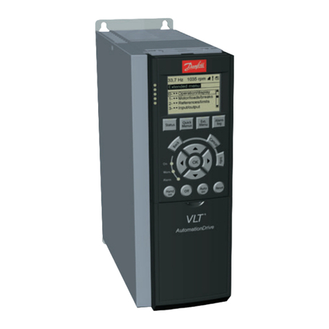
  9. Danfoss VLT 28 User manual

Danfoss VLT 28 User manual

This manual suits for next models

9

Other Danfoss DC Drive manuals

Danfoss VLT AQUA Drive FC 200 User manual

Danfoss

Danfoss VLT AQUA Drive FC 200 User manual

Danfoss MCD 500 User manual

Danfoss

Danfoss MCD 500 User manual

Danfoss VLT HVAC Drive FC 102 User manual

Danfoss

Danfoss VLT HVAC Drive FC 102 User manual

Danfoss VLT HVAC Drive Metasys N2 User manual

Danfoss

Danfoss VLT HVAC Drive Metasys N2 User manual

Danfoss Native BACnet VLT HVAC Drive User manual

Danfoss

Danfoss Native BACnet VLT HVAC Drive User manual

Danfoss VLT Automation Drive FC 300 User manual

Danfoss

Danfoss VLT Automation Drive FC 300 User manual

Danfoss VLT HVAC Basic Drive FC 101 Guide

Danfoss

Danfoss VLT HVAC Basic Drive FC 101 Guide

Danfoss VLT HVAC FC 100 User manual

Danfoss

Danfoss VLT HVAC FC 100 User manual

Danfoss VLT FC 103 Operating instructions

Danfoss

Danfoss VLT FC 103 Operating instructions

Danfoss VLT series Guide

Danfoss

Danfoss VLT series Guide

Danfoss VLT HVAC Drive FC 102 User manual

Danfoss

Danfoss VLT HVAC Drive FC 102 User manual

Danfoss VLT AutomationDrive FC 302 Guide

Danfoss

Danfoss VLT AutomationDrive FC 302 Guide

Danfoss VLT 6000 HVAC Series Specification sheet

Danfoss

Danfoss VLT 6000 HVAC Series Specification sheet

Danfoss Holip HLP-V Series User manual

Danfoss

Danfoss Holip HLP-V Series User manual

Danfoss VLT HVAC Drive FC 102 User manual

Danfoss

Danfoss VLT HVAC Drive FC 102 User manual

Danfoss VLT PTC Thermistor Card MCB 112 User manual

Danfoss

Danfoss VLT PTC Thermistor Card MCB 112 User manual

Danfoss VLT CDS 803 User manual

Danfoss

Danfoss VLT CDS 803 User manual

Danfoss vlt fcd 302 Guide

Danfoss

Danfoss vlt fcd 302 Guide

Danfoss VACON 20 X User manual

Danfoss

Danfoss VACON 20 X User manual

Danfoss FC 100 Series User manual

Danfoss

Danfoss FC 100 Series User manual

Danfoss VLT FCM Series User manual

Danfoss

Danfoss VLT FCM Series User manual

Danfoss VACON 100 industrial User manual

Danfoss

Danfoss VACON 100 industrial User manual

Danfoss VLT FC 103 Operating instructions

Danfoss

Danfoss VLT FC 103 Operating instructions

Danfoss VLT AutomationDrive FC 300 User manual

Danfoss

Danfoss VLT AutomationDrive FC 300 User manual

Popular DC Drive manuals by other brands

National Instruments NI MID-7604 user guide

National Instruments

National Instruments NI MID-7604 user guide

SOMFY Maestria WT Series instructions

SOMFY

SOMFY Maestria WT Series instructions

Trane TR150 Service manual

Trane

Trane TR150 Service manual

Chamberlain Garog D Series operating manual

Chamberlain Garog

Chamberlain Garog D Series operating manual

Parker PDS Series user guide

Parker

Parker PDS Series user guide

Binks QS-5012-1-CE Service manual

Binks

Binks QS-5012-1-CE Service manual

YASKAWA CANopen SI-S3 Technical manual

YASKAWA

YASKAWA CANopen SI-S3 Technical manual

GE D20A6 instructions

GE

GE D20A6 instructions

Lenze PositionServo 940 user manual

Lenze

Lenze PositionServo 940 user manual

Unex MC-D-250-1000-050W-TW operating manual

Unex

Unex MC-D-250-1000-050W-TW operating manual

Geckodrive G213V manual

Geckodrive

Geckodrive G213V manual

ABB RSYC-01 user manual

ABB

ABB RSYC-01 user manual

Rockwell Automation PowerFlex 700S Programming manual

Rockwell Automation

Rockwell Automation PowerFlex 700S Programming manual

WEG DeviceNet CFW500 user manual

WEG

WEG DeviceNet CFW500 user manual

Siemens SINAMICS G List manual

Siemens

Siemens SINAMICS G List manual

Siemens SINAMICS SM150 6SL3815-7NP41-0AA1 Operating instructions & installation instructions

Siemens

Siemens SINAMICS SM150 6SL3815-7NP41-0AA1 Operating instructions & installation instructions

SOMFY JR RU 30 instructions

SOMFY

SOMFY JR RU 30 instructions

Beckhoff AX8911 Documentation

Beckhoff

Beckhoff AX8911 Documentation

manuals.online logo
manuals.online logoBrands
  • About & Mission
  • Contact us
  • Privacy Policy
  • Terms and Conditions

Copyright 2025 Manuals.Online. All Rights Reserved.

VLT® 2800 Series
■Hig voltage warning
The voltage of the adjusta le frequency
drive is dangerous whenever the drive is
connected to electrical current. Incorrect
fitting of the motor or adjusta le frequency drive may
cause damage to the equipment, serious injury or
death. Consequently, it is essential to comply with
the instructions in this manual as well as local and
national rules and safety regulations.
■T ese rules concern your safety:
1. Disconnect the adjusta le frequency drive from
the AC line if repair work is to e carried out. Wait
4 minutes to allow for electrical discharge efore
removing motor and AC line connectors.
2. The [STOP/RESET] key on the control panel
of the adjusta le frequency drive does not
disconnect the equipment from the AC line.
Do not use it as a safety switch.
3. The unit must e grounded correctly. The user
must e protected against supply voltage and the
motor protected against overload in accordance
with applica le national and local regulations.
4. The ground leakage currents are higher than 3.5 mA.
5. Protection against motor overload is not included in
the factory setting. If this function is required, set
parameter 128 Motor thermal protection to ETR
trip or ETR warning. For North America: The ETR
functions provide class 20 overload protection for
the motor, in accordance with NEC requirements.
6. Do not remove the terminal plugs for the motor
and AC line supply while the adjusta le frequency
drive is connected to the AC line. Ensure that
the AC line supply has een disconnected and
that 4 minutes has passed efore removing
motor and AC line plugs.
7. The DC us terminals are another high voltage
input that must e disconnected efore servicing
thedrive. Ensurethatallvoltageinputshave
een disconnected and that 4 minutes has
passed efore repair work egins.
■Warnings against unintended start:
1. The motor can e started y means of digital
commands, us commands, references or
a local start command whenever the drive
is connected to the AC line. Therefore, an
unintended start may occur anytime power is
applied. Never service the drive or equipment
when power is applied to the drive.
2. The motor may start while parameters are
eing changed. Always activate the stop key
[STOP/RESET] y pressing it efore data is modified.
3. A motor that has een stopped may start if
faults occur in the electronics of the drive, or
if a temporary overload or fault clears in the
AC line or motor connection.
■Motor overload protection
The electronic thermal relay (ETR) in UL listed
VLTs provides Class 20 motor overload protection
in accordance with the NEC in single motor
applications when parameter 128 is set for "ETR
TRIP" and parameter 105 Motor current is set
for the rated motor current.
195NA139.10
Warning:
It can e extremely dangerous to touch the electrical parts
even when the mains supply has een disconnected.
Also ensure that other voltage inputs are disconnected
from load sharing through the DC us.
Wait at least 4 minutes after the input power has een
removed efore servicing the drive.
MG.28.A8.22 - VLT is a registered Danfoss trademark
4
VLT® 2800 Series
Installation
■Mec anical dimensions
The drawings elow give the mechanical dimensions.
All dimensions are in mm.
VLT 2803-2815 200-240 Volt
VLT 2805-2815 380-480 Volt
The drawing elow gives the mechanical dimensions of
VLT 2822 (3 HP) 200-240 Volts and VLT 2822-2840 (3
- 5 HP) 380-480 Volts. All dimensions are in inches.
VLT 2822 200-240 Volt
VLT 2822-2840 380-480 Volt
The drawing elow gives the mechanical dimensions of
VLT 2840 (5 HP) 200-240 Volt and VLT 2855-2875 (7 -
10HP) 380-480 Volt. All dimensions are in inches.
VLT 2840 200-240 Volt
VLT 2855-2875 380-480 Volt
VLT 2880-82 380-480V
MG.28.A8.22 - VLT is a registered Danfoss trademark 5
VLT® 2800 Series
■Motor coils (195N3110)
■RFI 1B filter (195N3103)
■Terminal cover
The drawing elow gives the dimensions for NEMA
1 terminal covers for VLT 2803-2875.
Dimension ’a’depends on the unit type.
■IP 21 solution
MG.28.A8.22 - VLT is a registered Danfoss trademark
6
VLT® 2800 Series
Installation
Dimensions
Typ e Code num er A B C
VLT 2803-2815 200-240 V, VLT 2805-2815 380-480 V 195N2118 47 80 170
VLT 2822 200-240 V, VLT 2822-2840 380-480 V 195N2119 47 95 170
VLT 2840 200-240 V, VLT 2855-2875 380-480 V 195N2120 47 145 170
VLT 2880-2882 380-480 V 195N2126 47 205 245
■EMC filter for long motor cables
192H4719
MG.28.A8.22 - VLT is a registered Danfoss trademark 7
VLT® 2800 Series
192H4720
192H4893
MG.28.A8.22 - VLT is a registered Danfoss trademark
8
VLT® 2800 Series
Installation
■Mec anical installation
The adjusta le frequency drive is cooled y air
circulation. For proper cooling, allow a minimum
of 4 inches (100 mm) of open space a ove and
elow the unit. To protect the unit from overheating,
ensure that oth the am ient temperature and the
24-hour average temperature are not exceeded.
The maximum temperature and 24-hour average
are listed in General technical data in this manual. If
the am ient temperature is in the range of 113°F -
131°F (45°C - 55°C), derating of the drive must e
carried out. See Derating for ambient temperature
in this manual. The service life of the unit will e
reduced without applica le derating.
The requirements that apply to enclosures
and remote mounting must e complied
with to avoid serious injury or equipment
damage, especially when installing large units.
■Enclosures
In the USA and some other countries, a NEMA 1
terminal cover enclosing terminal connectors is required
if the drive is not installed within another enclosure.
■Spacing for mec anical installation
All units require a minimum of 4 in of air from other
components a ove and elow the enclosure.
■Side-by-side
All VLT 2800 units can e installed side- y-side
and in any position, as the units do not require
ventilation on the side.
NOTE
With the IP 21 solution all units require a
minimum of 4 in air on each side. This means
that side- y-side mounting is not allowed.
MG.28.A8.22 - VLT is a registered Danfoss trademark 9
VLT® 2800 Series
■General information about electrical installation
■Hig voltage warning
The voltage of the adjusta le frequency
drive is dangerous whenever the drive
is connected to the AC line. Incorrect
installation of the motor or drive may cause damage
to the equipment, serious injury or death. Comply
with the safety instructions in this manual as well
as local and national rules and safety regulations.
Touching electrical parts may e fatal - even after the
equipment has een disconnected from the AC line.
Wait at least 4 minutes for current to dissipate.
NOTE
It is the responsi ility of the user or installer
to ensure correct grounding and protection in
accordance with national and local standards.
■Grounding
Comply with the following at installation:
•Safety grounding: The drive has a high leakage
current and must e grounded properly for safety.
Follow all local safety regulations.
•High frequency grounding: Keep grounding
ca les as short as possi le.
Connect all grounds to ensure the lowest possi le
conductor impedance. The lowest possi le conductor
impedance is achieved y keeping the conductor as
short as possi le and y grounding with the greatest
possi le surface area. If multiple drives are installed
in a ca inet, the ca inet ackplate, which must e
made of metal, should e used as a joint ground
referenceplate. Thedrivesmust efittedtothe
ackplate at the lowest possi le impedance.
To achieve low impedance, connect the drive to the
ackplate with the drive fastening olts. Remove
all paint from the contact points.
■Hig voltage test
A high voltage test can e performed y short-circuiting
terminalsU,V,W,L1,L2andL3,andapplying
max. 2160 V DC in 1 sec. etween this
short-circuit and terminal 95.
MG.28.A8.22 - VLT is a registered Danfoss trademark
10
VLT® 2800 Series
Installation
■EMC-correct electrical installation
General points to e o served to ensure
EMC-correct electrical installation.
- Use only shielded/armoured motor ca les and
shielded/armoured control ca les.
- Connect the screen to ground at oth ends.
- Avoid installation with twisted shield ends (pigtails),
since this ruins the shielding effect at high
frequencies. Use ca le clamps instead.
- It is important to ensure good electrical contact from
the installation plate through the installation screws
to the metal ca inet of the varia le frequency drive.
- Use starwashers and galvanically conductive
installation plates.
- Do not use unshielded/unarmoured motor
ca les in the installation ca inets.
The illustration elow shows EMC-correct electrical
installation, in which the varia le frequency
drive has een fitted in an installation ca inet
and connected to a PLC.
MG.28.A8.22 - VLT is a registered Danfoss trademark 11
VLT® 2800 Series
■Grounding of s ielded/armoured control cables
In general control ca les must e shielded/armoured,
and the shield must e connected to the unit’s metal
ca inet with a ca le clamp at each end.
The drawing elow shows the correct way to perform
the grounding, and what to do when in dou t.
1. Correct grounding
Control ca les and ca les for serial
communication must e attached with ca le
clamps at oth ends to ensure maximum
possi le electrical contact.
2. Incorrect grounding
Do not use twisted shield ends that are
plaited together (pigtails), as these increase shield
impedance at higher frequencies.
3. Protection wit respect to ground
potential between PLC and VLT
f the ground potential etween the VLT
varia le frequency drive and the PLC (etc.)
is different, electric noise may occur that will
distur the whole system. This pro lem can
e solved y fitting an equalising ca le, to e
placed next to the control ca le. Minimum ca le
cross-section: 6 AWG (16 mm2).
4. n t e event of a 50/60 Hz ground loop
If very long control ca les are used, 50/60 Hz
ground loops can arise, and these can interfere
with the whole system. This pro lem is resolved
y attaching one end of the shield to the ground
via a 100 nF capacitor (short pin length).
MG.28.A8.22 - VLT is a registered Danfoss trademark
12
VLT® 2800 Series
Installation
■Diagram
* Integrated 1A RFI filter and rake is an option.
** VLT 2803-2815 200-240 V is not supplied
with intermediate circuit coils.
MG.28.A8.22 - VLT is a registered Danfoss trademark 13