Endo EWA-15 User manual

INSTRUCTION MANUAL
SPRING BALANCER
EWA-15
ENDO KOGYO CO., LTD.
BM-10097
WARNING
・Read this manual before use.
・Keep this manual available.
Issued on Dec. 2012
Copied digital data
from http://www.endo-kogyo.co.jp/

Copyright and liabilities
The copyright for this manual belongs to Endo Kogyo Co., Ltd.
The manual is provided for the limited purpose of supporting the safe and proper use of
the product. It cannot be used for other purposes.
The customer may not use or make copies of this manual, in whole or in part, outside of
this purpose without receiving prior consent from Endo Kogyo Co., Ltd.
The customer is also prohibited from translating or modifying the content of the manual,
in whole or in part.
The content described in the manual is subject to change without advance notice.
Please note this in advance.
November 2019 ENDO KOGYO CO., LTD.
Copied digital data
from http://www.endo-kogyo.co.jp/
SAFETY ALERT SYMBOL AND ALERT SIGNS SIGNS
Please read this manual carefully and follow its instructions.
The SAFETY ALERT SYMBOL ( ), WARNING, CAUTION, and NOTE carry
special messages.
This SAFETY ALERT SYMBOL is used to call your attention to
items or operations that could be dangerous to you or other persons
using this equipment.
Please read these messages and follow these instructions carefully.
:CAUTION indicates a hazardous situation which,
if not avoided, could result in minor or moderate
injury, damage or destruction of the equipment and
others.
:WARNING indicates a hazardous situation which,
if not avoided, could result in death or serious
injury.
NOTE:NOTE indicates a special instruction in operation or maintenance.
Copied digital data
from http://www.endo-kogyo.co.jp/

Scope of warranty and liabilities for the equipment
1. We will repair or replace the product free of charge if a failure due to manufacturing defects
occurs under proper usage during the warranty period.
For details, contact us or your dealer.
2. The warranty will be void in the following cases:
1) Change in ownership.
2) Repair, adjustment, or modification performed by a party other than the manufacturer, agents,
or dealers.
3. Warranty period is 1 year from your purchase.
However, wire rope, wire guide and spring are not covered by warranty.
4. Repairs applicable to any of the following shall be charged even during the warranty period:
1) Failure/damage caused by incorrect use.
2) Failure/damage caused by use of non-genuine parts.
3) Failure/damage caused by fire, earthquake, natural disaster, or other unexpected incident.
4) Incident caused by fall, shock, negligence, or by inadequate storage.
5) Failure/damage caused by use of parts or other equipment that are not included in this product.
6) Replacement of consumables.
7) Usage in violation of dangers or cautions stipulated in this Instruction Manual or the warning
labels.
8) Failure/damage caused by any reason that is not attributable to the manufacturer.
5. Warranty exclusions such as opportunity loss.
Either during or after the warranty period, opportunity loss, damage to anything other than our
product(s), or other duties incurred on you/your customer as a result of the failure of our
product(s) are outside the scope of the warranty.
Copied digital data
from http://www.endo-kogyo.co.jp/

CONTENTS
1. Safety instructions・・・・・・・・・・・・・・・・・・・・・・・・・・・・・・・・・・・・・・・・・・・・1
2. Description of product・・・・・・・・・・・・・・・・・・・・・・・・・・・・・・・・・・・・・・・・・・・・・2
2-1. Specifications
2-2. Main features
3. Installation・・・・・・・・・・・・・・・・・・・・・・・・・・・・・・・・・・・・・・・・・・・・・・・・・2
3.1. Balancer installation
3.2. Tool/device attachment and spring tension adjustment
3.3. Working stroke (cable travel) check
4. Use・・・・・・・・・・・・・・・・・・・・・・・・・・・・・・・・・・・・・・・・・・・・・・・・・・・・・・・・・・・・・・4
4.1. Safety instructions on use
4.2. Drum lock operation
4.3. Tool/device replacement
5. Troubleshooting・・・・・・・・・・・・・・・・・・・・・・・・・・・・・・・・・・・・・・・・・・・・・・・・・・・・6
5.1. Common malfunctions and their causes
5.2. Solutions
6. Inspections・・・・・・・・・・・・・・・・・・・・・・・・・・・・・・・・・・・・・・・・・・・・・・・・・・・・・・・・9
7. Wire rope replacement・・・・・・・・・・・・・・・・・・・・・・・・・・・・・・・・・・・・・・・・・・・・・10
8. Spring replacement・・・・・・・・・・・・・・・・・・・・・・・・・・・・・・・・・・・・・・・・・・・・・・・10
9. Wire guide replacement・・・・・・・・・・・・・・・・・・・・・・・・・・・・・・・・・・・・・・・・・・・・12
10. Parts list・・・・・・・・・・・・・・・・・・・・・・・・・・・・・・・・・・・・・・・・・・・・・・・・・・・・・・・・13
Copied digital data
from http://www.endo-kogyo.co.jp/
1. Safety Instructions
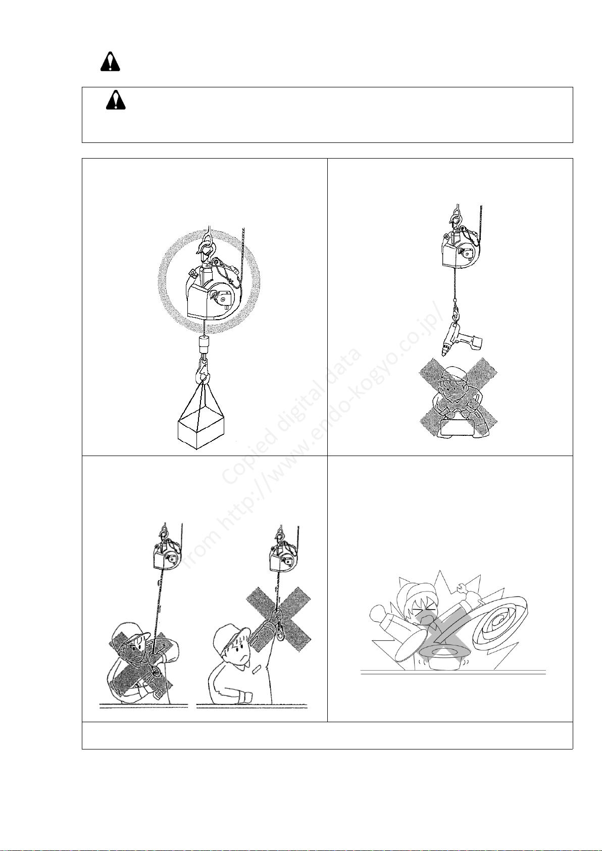
WARNING
・Incorrect use of the spring balancer could personal injury.
・Observe instructions in the manual and use the balancer correctly.
・Install the balancer correctly. ・Never stand under the suspended
・Always attach a secondary support tool/device.
cable or chain.
・Never remove tool/device while the wire ・Be careful when handling the spring.
rope is extended.
・Never pull the wire rope when unloaded.
・Never release the drum lock when unloaded.
・Never alter the balancer.
・Periodically inspect the balancer.
Copied digital data
from http://www.endo-kogyo.co.jp/
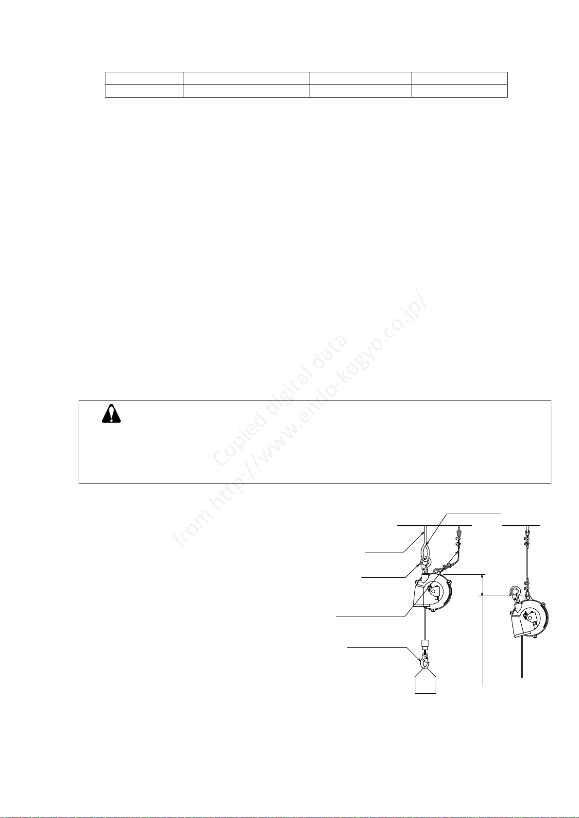
YBM000255
W i t h i n 1 0 0 m m
No opening
Fitting
Top hook
Bottom hook
Secondary
support cable
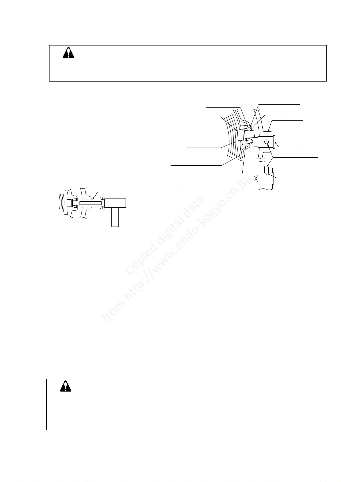
2. Description of product
2-1. Specifications
Model
Capacity range(kg)
Cable travel(m)
Mass(kg)
EWA-15
9~15
1.3
Approx.4.7
■Working conditions Application area : Indoor and normal atmospheric conditions
Temperature range: -10 ゚C to +50 ゚C
2-2. Main features
■Fall prevention device
A mechanism to prevent the suspended tool/device from falling to the maximum cable
travel in case of spring breakage.
This mechanism can not prevent the tool/device from falling at all when the spring
breaks.
■Drum lock (See Chapter 4-2 "Drum lock operation")
A mechanism to lock the drum at every 1/6 turn.
This mechanism is used when removing the suspended tool/device (see Chapter 4-3) or
replacing the wire rope (see Chapter 7).
■A snap back arrest device
This device is provided to arrest Wire rope snap back in case that Wire rope is cut or
suspended tool is disengaged. As soon as Wire rope is cut, drum revolves rapidly
winding Wire rope up. The centrifugal force makes Ratchet on a spring case pushed out
and the ratchet sticks in wheel fixed on a cover, stopping the revolution of the drum.
This is not engineered to keep the machine away from Wire rope snap back in advance.
Snap back arrest device works when the length of pulled wire is between 300mm and
1300mm. Between 100m and 200m of Wire rope must be wound very fast until Snap back
arrest device works in case of the cutting.
The device is only for emergency.
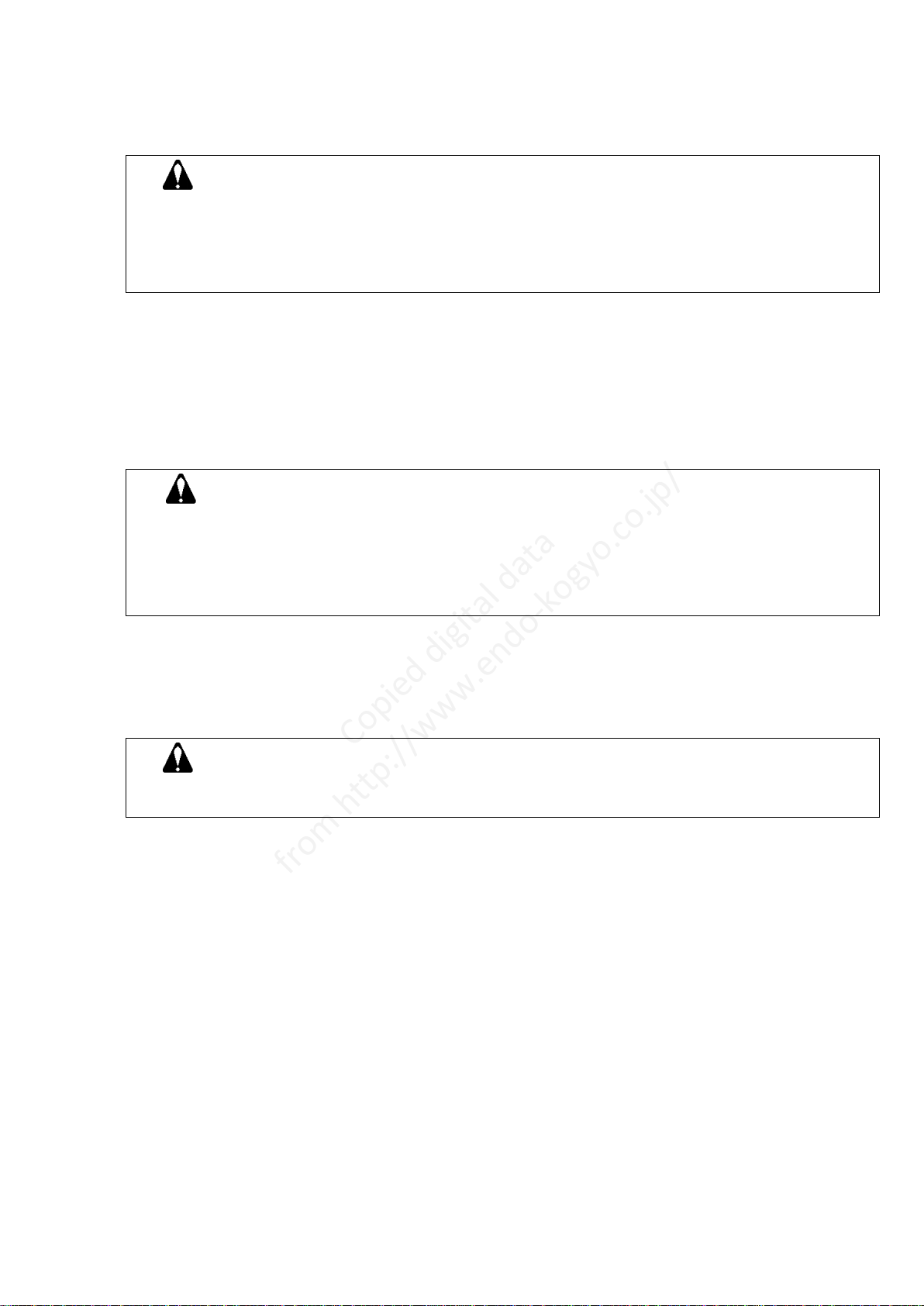
3. Installation
3-1. Balancer installation
WARNING
・Install the balancer correctly.
Incorrect installation could cause personal injury or damage to the balancer or other equipment.
・Always attach a secondary support cable or chain.
It is required to protect personnel in case of failure of the top hook or the fitting.
1) Prepare a fitting that can support at least 10 times . Fig.1
the maximum capacity of the balancer .
NOTE: The fitting must have no opening as
shown in Fig. 1 to prevent the balancer
from disengaging when it swings.
2) Attach the top hook of the balancer directly to
the fitting. Check the latch is closed.
NOTE: Take care the balancer does not hit
surrounding objects.
Make the mounting height different for
each balancer to avoid collision.
3) Check the top hook can swivel freely.
NOTE: Do not fasten the top hook to the balancer
body.
4) Prepare a secondary support cable or chain that
can support at least 10 times
the maximum capacity of the balancer .
5) As shown in Fig. 1, attach an end of the secondary
support cable or chain to the balancer body,
and attach the other end to a separate fitting which does not support the balancer.
NOTE: Leave some slack in the secondary support cable or chain to allow the balancer
to rotate freely. The slack must be a suitable length so that the balancer will stop
within 100 mm when falling in case of failure of the top hook or the fitting (See Fig. 1).
Copied digital data
from http://www.endo-kogyo.co.jp/

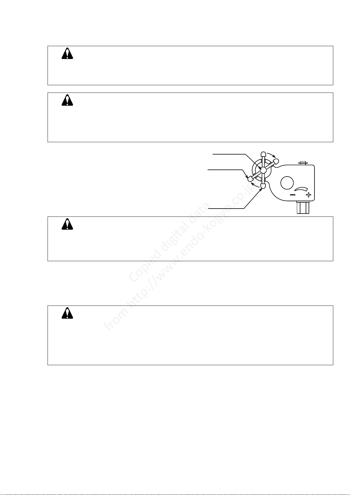
Pin(8)
Release
position
Lock
position
4. Use
4-1. Safety instructions on use
WARNING
・Never remove tool/device from the bottom hook while the wire rope is extended.
・Never stand under the suspended tool/device.
・Never alter the balancer.
CAUTION
・Always use within the capacity range of the balancer.
・Always adjust the spring tension before use.
・Do not extend the wire rope past the maximum cable travel.
・Do not pull the wire rope at an angle.
Fig.3
4-2. Drum Lock operation
1) Pull Pin (8) out and turn it clockwise to place
in the lock position (See Fig. 3).
2) Move the suspended tool/device upward or
downward until Pin (8) enters the slot/ hole in
the drum and the drum becomes locked.
3) Move the tool/device again to check the drum is
locked securely.
4) Remove the tool/device from the bottom hook.
WARNING
Never remove the suspended tool/device before checking the drum is locked securely.
If the drum is not locked securely, the drum lock could be released allowing the wire rope to snap
back, possibly causing personal injury.
Drum lock check is very important factor for safety . Never fail to verify the sufficient drum lock .
5) Before releasing the drum lock, attach a new tool/device if the old one has been removed.
The new tool/device must have almost the same mass (weight) as the old one.
6) Release the drum lock by pulling Pin (8) out.
Turn Pin (8) counterclockwise and place it in the release position.
WARNING
Never release the drum lock when the balancer is unloaded or the new tool/device has a different
mass (weight) to the old one.
If released, the wire rope will snap back or the tool/device could drop down respectively, possibly
causing personal injury.
Always release the drum lock after arranging the tension of spring suspending a tool.
This is important factor for safety. Never fail to abide by procedure instructed in the manual.
Copied digital data
from http://www.endo-kogyo.co.jp/
4-3. Tool/device replacement
■Method 1 - With drum lock
1) Lock the drum according to Chapter 4-2 "Drum lock operation" Remove the suspended
tool/device.
WARNING
Move the tool/device upward and downward to check the drum is locked securely.
Never remove the tool/device before checking this.
If the drum is not locked securely, the drum lock could be released allowing the wire rope to snap
back, possibly causing personal injury.
Drum lock check is very important factor for safety. Never fail to verify the sufficient drum lock.
2) Before attaching, check the mass (weight) of the new complete tool/device, including all
accessories, is within the capacity range of the balancer.
3) While watching the gauge, pre-adjust the spring tension to the mass of the new complete
tool/device by turning the worm with a wrench etc.
Turn clockwise for increasing the spring tension, turn counterclockwise for reducing.
The gauge shows the approximate spring tension (see Fig.2).
4) Attach the new complete tool/device to the bottom hook. Releasing the drum lock
WARNING
Never release the drum lock when the balancer is unloaded.
If released, the wire rope will snap back, possibly causing personal injury.
Always hold the suspended new tool/device by hand when releasing the drum lock, if the new
tool/device has a different mass (weight) to the old one.
Otherwise, the tool/device could rise up or drop down suddenly, possibly causing personal injury.
5) After attaching the new complete tool/device and releasing the drum lock, adjust the spring
tension again and check the tool/device is balanced.
NOTE: Over-tensioning could cause damage to the balancer body or the wire rope.
■Method 2 - Without drum lock
WARNING
Never remove the suspended tool/device while the wire rope is extended.
If removed, the wire rope will snap back and could cause personal injury.
1) Lift then remove the suspended tool/device when the wire rope is fully retracted.
2) Attach a new tool/device according to Chapter 3-2
"Tool/device attachment and spring tension adjustment".
Copied digital data
from http://www.endo-kogyo.co.jp/

5. Troubleshooting
WARNING
If a malfunction occurs during operation, stop operation immediately and take the necessary steps
to rectify the problem.
Never remove the suspended tool/device before identifying causes of the malfunction.
If removed, the wire rope will snap back and could cause personal injury.
Never take off a tool suspend to make the work safe. Wire rope snap back protection is for only
emergency.
5-1. Common malfunctions and their causes
Malfunction
Cause
Solution
・Wire rope cannot be pulled
out and retracted.
・Drum lock is engaged.
・Fall prevention device is
engaged because the spring
tension is set under the
maximum capacity .
・Wire rope has slipped
off from the drum groove and
is caught between drum and
casing.
・Spring has broken.
・Release drum lock
See Chapter 4-2 .
・Release fall prevention device
See Chapter 5-2 .
・Return wire rope
to the drum groove.
See Chapter 5-2.
・Replace spring.
See Chapter 8.
・Wire rope can not be
retrieved.
・Wire rope snap back
protection actuated
・Wire rope has slipped off from
the drum groove and is
caught between drum and
casing .
・Release the wire rope snap
back protection See Chapter
5-2 .
・Return wire rope to the drum
groove . See Chapter 5-2.
Contact your dealer or us if a malfunction not listed above occurs.
5-2. Solutions (Refer to the disassembly drawings on page 13)
CAUTION
Careless repairs can cause personal injury or damage to the balancer.
Therefore, be careful but thorough when making repairs.
■When the fall prevention device has engaged because the spring tension is set under the
minimum capacity
1) Move the suspended tool/device upward and downward by hand.
The tool/device can be moved about 70 to 140 mm.
If the tool/device raises after being lowered and then released, turn Worm (49)
counterclockwise until the toll/device starts dropping down. If the tool/device drops down
after being lifted and then released, turn Worm clockwise until the tool/device starts rising.
2) Loosen Set screws (13), and remove all pins (12) while holding the tool/device by hand.
NOTE: For safety reasons, perform this work with two persons.
3) Lift then remove the tool/device from bottom Hook (40) when check the mass (weight) of
removed tool/device is within the capacity range of the balancer.
4) Attach a weight, which has been measured to be within the capacity range, to bottom Hook
(40) and adjust the spring tension.
5) Move the tool/device upward or downward so that Safety pin (52) appears at the opening (cut
off portion) of Causing (1).
6) Check safety pin (52) does not project out from the surface of Spacer (54).If protruding, lightly
tap the top of safety pin with a plastic hammer etc.
7) If safety pin does not return, it has burrs or spring (53) is broken. Remove Spacer (54) and
check Safety pin. Spring (53) pops out when Spacer (54) is removed, therefore be careful not
to lose it.
Copied digital data
from http://www.endo-kogyo.co.jp/
8) Attach Pins (12) to Casing (1).
Fasten depressions in pins (12) with set screws (13).
Fig. 4
■When the wire rope is caught between drum and casing
1) Release Wire rope (38) by jerking it strongly while the tool/device is suspended.
NOTE: After jerking, check Wire rope and replace if damaged.
2) If Wire rope can not be released by jerking, disassembly is required.
Remove Retaining ring (55) from Worm (49).
3) Release all spring tension by turning Worm (49) counterclockwise, and remove the balancer
from the fitting. .
4) Remove the tool/device from bottom Hook (40), and remove the balancer from the fitting.
5) Loosen Set Screws (13) and remove all pins (12).
6) Remove Gauge (50).
7) Loosen Cap screw (36), and remove Cover (32).
8) Return wire rope (38) to the groove of Drum (19).
NOTE: Check wire rope (38) and replace if damaged.
9) Install Cover (32)
10) Install Worm (49), and attach Retaining ring (55) .
11) Adjust the spring tension, and install Gage (50) and Pins (12) .
See Chapter 8 “Spring replacement”
■In case that the Wire rope snap back protection has actuated by sudden retrieve.
1) Pull out Wire rope (38) and release Ratchet (26), suspending a tool.
WARNING
Never remove the suspended tool when Wire rope snap back protection has actuated.
Release of Wire rope snap back protection may cause a serious danger, retrieving cable rapidly if
has performed without a tool suspended.
Wire rope pilling out one recovery work will release Wire rope snap back protection, causing
personal injury. Wire rope will be retrieved about 100mm-200mm rapidly.
2) If Ratchet is not released despite cable pulls out enough, Lock the drum according to Chapter
4-2 Drum lock operation.
3) Remove Retaining ring (55) from Worm (49) after checking the sure lock of drum.
WARNING
If installation of Safety pin (52) or pins (12) is incorrect or missed, the fall prevention device will
not operate in case of spring breakage, causing personal injury or damage to equipment.
Spr ing case(21)
Depress ion
Casing(1)
Burr
Pin(12)
Set screw(13)
Spring(53)
Spring(20)
Sefety pin(52)
Spacer(54) Snapring(60)
Lightly hit the safety pin
through the installation
hole of pin using a plastic
hammer.
Copied digital data
from http://www.endo-kogyo.co.jp/

4) Release all spring tension by turning Worm (49) counterclockwise, and remove Worm.
5) Remove the tool/device from bottom (40), and remove the balancer from the fitting.
6) Loosen Set screw (13), and remove all pins (12).
7) Remove Gauge (50).
8) Remove Cap screw (36).
9) Remove Cover (32).
NOTE: Replace Wheel (34), Ratchet (26),Spring (31) etc. if they has damaged.
10) Install Cover (32).
11) Mount Cap screw (36).
12) Install Worm (49), and attach Retaining ring (55).
13) Adjust the spring tension, and install Gauge (50) and Pins (12).
See chapter 8 “Spring replacement”, 10-11)
■In case that Snap back protection has actuated due to wire rope cut etc.
WARNING
If snap back protection has actuated due to Wire rope cut etc, Stop operation at once and
perform proper solution. Wire rope will be retrieved suddenly, causing injury of personal in
case that the damaged Wire rope is pulled out or machine receives excessive shock.
Wire rope pulling out or excessive shock to the Balancer will release Wire rope snap back
protection, causing personnel injury. Wire rope will be retrieved about 100mm -200mm
rapidly.
1) Lock Drum according to Chapter 4-2 [Drum lock operation]
2) Remove retaining ring (55) from Worm (49) after checking the sure lock of drum.
3) Release all spring tension by turning Worm (49) counterclockwise, and remove Worm.
4) Take off a Spring balancer from the support.
5) Loosen Set screw (13), and remove all pins (12).
6) Remove Gauge (50).
7) Remove Cap screw (36).
8) Remove Cover (32).
NOTE: Replace Wheel (34), Ratchet (26), Spring (31) etc. if they has been damaged.
9) Install Cover (32).
10) Mount Cap screw (36)
11) Install Worm (49), and attach Retaining ring (55).
12) Equip Wire rope (38) to Drum (19) after passing Wire rope through the Wire rope entrance
on Casing (1) and then fix wire rope with Plug (48).
13) Adjust the spring tension, and install Gauge (50) and Pins (12).
See Chapter 8 “Spring replacement”
Copied digital data
from http://www.endo-kogyo.co.jp/
B
D
A
C
Is a retaining ring
taken off?
Are any pins or
safety pin missing?
Is there any
wear or damage?
Top hook
Latch
Is there any
deformation?
swivel smoothly?
Can hook
Casing,Drum
Is there any
wear or damage?
Wire guide
Are there any wear
or cracks?
Are screws loose?
Latch
Is there any
deformation?
Secondary support
cable(chain)
Is there any damage?
Are bolts loose?
Is there any wear or damage?
Are screws loose?
Wire rope
Is there any damage?
Check for wire
near the lock tube.
breakage or damage
Buffer
Is there any wear
or cracks?
Collar
Move upward during
inspection.
Is there any wear
or damage?
Thimble,Bottom hook
Bottom hook
Fitting
1 Pitch
There must be no kinks.
H
8.0mm
Y B M 0 0 0 2 1 1
16.5mm
41.0mm
6. Inspections
WARNING
Periodically inspect the balancer, and replace any worn or damaged parts.
CAUTION
Always use genuine parts for replacement.
■Inspect the balancer at least once a month.
Correct and repair any problems which are detected.
Make the inspection interval shorter when operating frequently or under hostile environments.
(See Fig. 5)
■Service limit of top hook Fig.5
Limit dimension (mm)
A
B
C
D
11.7
15.5
44.0
1.5
■Service limit of bottom hook ■Service limit of wire rope
H dimension (mm)
Allowable number of
broken wires in 1 pitch
Standard
Limit
4
3.7
11
Copied digital data
from http://www.endo-kogyo.co.jp/
W i n d o w
W i r e r o p e
P l u g ( 4 8 )
P i n ( 8 )
H o o k ( 4 0 )
Collar(46)
B u f f e r ( 4 7 )
W i r e r o p e ( 3 8 )
Drum(19)
W i r e r o p e
e n t r a n c e h o l e
A
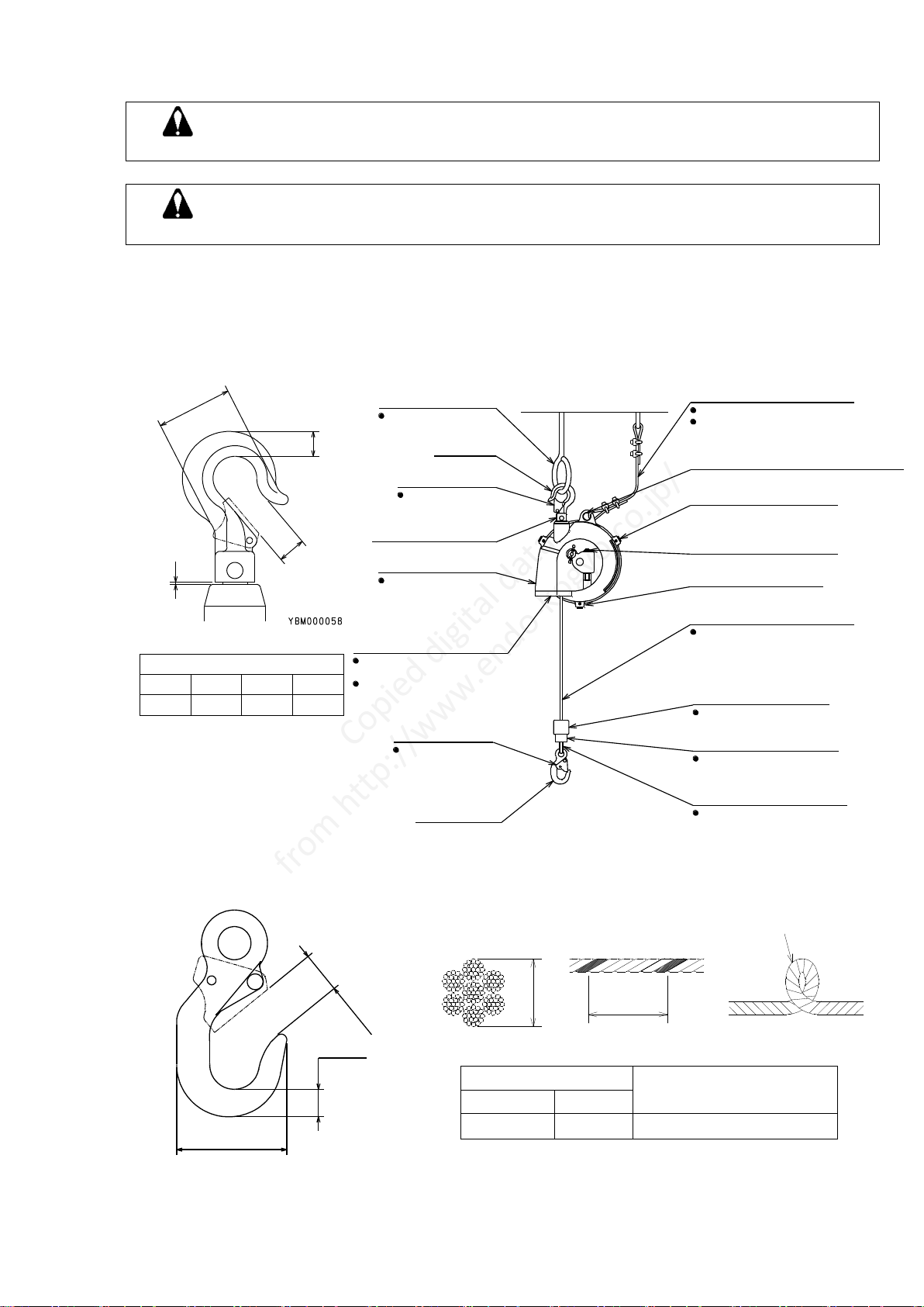
7. Wire rope replacement Fig.6
1) Lower the tool/device, extending Wire rope to
the maximum cable travel.
2) Position Plug (48) at the casing opening as
shown in Fig. 6, and engage the drum lock.
See Chapter 4-2 "Drum lock operation".
3) Move the tool/device upward and downward to
check Drum is locked securely. Remove the
tool/device from bottom Hook (40).
4) Remove the balancer from the fitting and place on the floor.
5) Remove Plug (48), and remove old Wire rope from drum.
6) Insert new Wire rope from A-side, pass it through Drum.
7) Attach the end of Wire rope to Drum and fasten with plug (48).
8) Install the balancer on the fitting.
See Chapter 3-1 “Balancer installation”
9) Attach the tool/device to bottom Hook, and release the drum lock.
WARNING
Never release the drum lock before attaching the tool/device.
If released, Wire rope (38) will snap back and could cause personal injury.
Always release the drum lock after arranging the tension of spring suspending a tool. This is
important factor for safety. Never fail to abide by the procedure instructed in the manual.
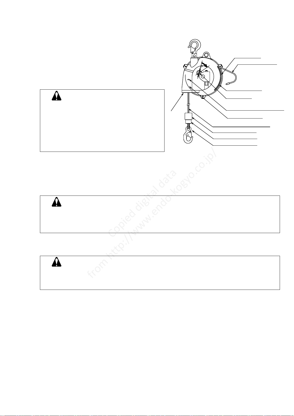
8. Spring replacement
WARNING
Never remove the spring from the spring case. If removed, the spring will expand explosively and
cause personal injury.
Replace the spring assembly as a whole.
Referring to the disassembly drawing (on page13), disassemble the balancer using the following
procedure.
1) A. When the spring has broken;
Remove the tool/device from bottom Hook (40).
B. When the spring has not broken;
Lift then remove the tool/device from bottom Hook (40) when Wire rope (38) is fully
retracted into Drum (19).
2) Remove the balancer from the fitting and place on the floor.
3) Remove Gauge (50)
4) Remove Retaining ring (55) from Worm (49). Release all spring tension by turning
worm (49) counterclockwise until Worm can almost be removed. If the drum lock is engaged,
check there is no spring tension remaining, and then release the drum lock.
NOTE: Check the spring tension by pulling Wire rope.
5) Turn Worm (49) further and remove it.
6) Loosen Set screws (13), and remove all Pins (12).
WARNING
Never remove the suspended tool/device before
checking Drum (19) is locked securely.
If Drum (19) is not locked securely, the drum lock
could be released allowing Wire rope to snap back
or Drum to rotate suddenly, possibly causing
personal injury.
Drum lock check is very important for safety.
Never fail to verify the sufficient in the manual.
Copied digital data
from http://www.endo-kogyo.co.jp/
Set screw(13)
Pin(12)
Depression
7) Remove Plug (48), and remove Wire rope (38) from Drum (19).
8) Remove Cover (32), and remove Spring case (21), Drum (19), and Spindle (15), together from
the Casing(1).
9) Remove Spindle (14).
10) Remove Hex. head bolt (24), and remove Spring case (21) from Drum (19).
11) Remove Bushing (23) from Spring case (21) .
WARNING
Never remove cover (22) from Spring case(21).
If removed, the internal spring could pop out and cause personal injury.
12) Reassemble in reverse order.
Pins (12) should be installed after adjusting the spring tension as instructed below.
13) Wind the spring by turning worm (49) clockwise.
NOTE: While turning Worm, Wire rope (38) will be retracted into drum (19). Pay attention
Wire rope does not slip out from the drum groove. After Wire rope is fully retracted,
turn worm 50 times.
14) Attach a weight, which has been measured to be within the capacity range,
to bottom Hook (40) and adjust the spring tension.
15) Attach and adjust Gauge (50).
16) Attach Pins (13) to Casing (1) ( See Fig.7)
fasten depressions in Pins (12) with set screws (13).
Fig.7
WARNING
If installation of Pins (12) is incorrect or missed, the fall prevention device will not
operate in case of spring breakage, causing personal injury or damage to equipment.
Copied digital data
from http://www.endo-kogyo.co.jp/

Hex. socket
button bolt(59)
Pin(8)
Wire guide(57)
(58)
9. Wire guide replacement
1) Pull out the wire rope (57), (58) to the position Fig. 8
which wire guide replacement is available
and lock drum with drum lock device(refer to Fig-8).
Refer to Chapter 4-2 ”Drum lock operation”.
2) After confirming that drum lock is surely
on work, moving a suspended tool up and down,
take off a suspended tool.
3) Remove the balancer from a fitting and place on the floor.
4) Remove Hex. Socket button bolts (59) are old wire guide from casing.
5) Fix new wire guide (57) (58)
NOTE: Hex. Socket button bolts (59) are sealed against looseness
Always replace old ones with new ones when they are remove.
Tighten the hex. Socket bolts with torque of 2.8~3.0N・m{0.28~0.3kgf・m}.
6) Mount the balancer on a fitting.
Refer to Chapter 3-1 “Balancer Installation”.
7) Attach the tool/device to bottom Hook, and release the drum lock.
WARNING
Never release the drum lock before attaching the tool/device.
If released, Wire rope will snap back and could cause personal injury.
WARNING
Never remove the suspended tool/device before
checking Drum (19) is locked securely. If Drum (19) is
not locked securely, the drum lock could be released
allowing Wire rope (38) to snap back or Drum to
rotate suddenly, possibly causing personal injury.
Copied digital data
from http://www.endo-kogyo.co.jp/
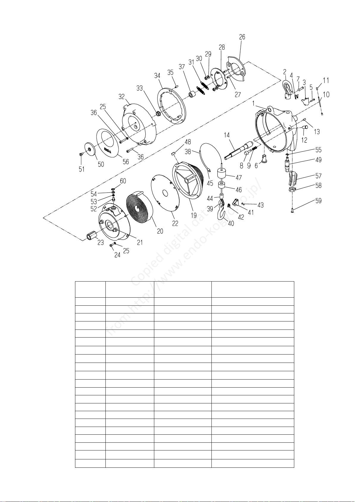
10. PARTS LIST EWA-15
Ref. No.
Part No.
Quantity
Description
-
LBP001097
1
Casing assembly
1
P2B100131
1
-Casing
-
LBP000262
1
-Hook complete
2
-
1
--Hook
-
LBP000263
1
--Latch set
3
-
1
---Latch
4
-
1
---Spring
5
-
1
---Rivet
6
-
1
--Shaft
7
-
1
--Rivet
8
P2B400347
1
-Pin
9
P2B400081
1
-Spring
10
P2B400224
1
-Spring pin
11
P2B400348
2
-Cap
12
P2B400044
3
-Pin
13
P2B400041
3
-Set screw
14
P2B301252
1
Spindle
19
P2B100045
1
Drum
-
LBP001661
1
Spring assembly
20
-
1
-Spring
21
-
1
-Spring case
Copied digital data
from http://www.endo-kogyo.co.jp/

Ref. No.
Part No.
Quantity
Description
-
LBP001822
1
-Safety pin set
52
-
1
--Safety pin
53
-
1
--Spring
54
-
1
--Spacer
60
-
1
--Retaining ring
22
-
1
-Cover
23
P2B300163
1
Bushing
24
KA00120510
4
Hex. head bolt
25
KA31120500
7
Spring washer
-
LBP001662
2
Ratchet set
26
-
2
-Ratchet
27
-
2
-Pin
28
P2B301254
1
Plate
29
KA31120600
2
Spring washer
30
KA20320600
2
Hex. nut
31
P2B401895
2
Spring
-
LBP001663
1
Cover complete
32
-
1
-Cover
33
-
1
-Bushing
34
P2B301255
1
Wheel
35
KA42410512
2
Spring pin
36
KA00910525
6
Cap screw
37
P2B401896
1
Collar
-
LBP000136
1
Wire rope assembly
38
-
1
-Wire rope
39
-
1
-Thimble
-
LBP001505
1
-Hook complete
40
-
1
--Hook
-
LBP001524
1
--Latch set
41
-
1
---Latch
42
-
1
---Spring
43
-
1
---Rivet
44
-
1
-Lock tube
45
-
1
-Lock tube
46
P2B400150
1
-Collar
47
P2B400147
1
-Buffer
48
P2B400007
1
Plug
49
P2B300062
1
Worm
50
P2B300166
1
Gauge
51
P2B400165
1
Screw
55
KA40310050
1
Retaining ring
56
P2B301256
1
Name plate
-
LBP001096
1
Wire guide set
57
-
1
-Wire guide
58
-
1
-Wire guide
59
P2B401213c
2
-Hex. socket button bolt
NOTE) When placing an order, clearly specify the product model, part number and description.
Parts without a part number cannot be supplied individually.
Please purchase a set or complete unit.
Copied digital data
from http://www.endo-kogyo.co.jp/

Table of contents
Other Endo Wheel Balancer manuals


