Dantel 46022-20 User manual
CAUTION
•Install or remove modules from the shelf only when the power is off.
If you install a module in the shelf with the power on, the internal
circuitry may suffer damage and the product warranty will be void.
•Remove and install circuit boards only in a static-safe environment
(use antistatic wrist straps, smocks, footwear, etc.).
•Keep circuit boards in their antistatic bags when they are not in use.
•Do not ship or store circuit boards near strong electrostatic, electromag-
netic, magnetic, or radioactive fields.
•For more complete information on electrostatic discharge safety
precautions, refer to BellcoreTM Technical Reference # TR-NWT-000870.
Copyright 1998 by Dantel, Inc. • Dantel is a registered trademark of Dantel, Inc. • ISO 9001 Registered
Printed in the U.S.A.
INSTALLATION & OPERATION MANUAL
46022-20-0398<90-00066>
46022-20
MULTIPLE ALARM
COMBINER (MAC)
About this Practice:
This practice has been reissued to:
• Meet ISO 9001 requirements.
Issue date: March 1998
Reissued Practices: Updated and
new content can be identified by a
banner in the right margin.
UPDATED
Table of Contents
Ordering Information ........................................................................... 2
General Description.............................................................................. 2
Circuit Description ............................................................................... 2
Installation............................................................................................ 3
Technical Specifications ....................................................................... 6
Warranty ............................................................................................... 8
46022-20
Multiple Alarm
Combiner
B11-46022-20 REV__

PAGE 2 46022-20-0398 <90-00066>
ORDERING INFORMATION
NOTE: This section lists the different options available for this product. To order any of the avail-
able options, contact Dantel Inside Sales through our toll-free number, 1-800-432-6835.
OPTION NUMBER FEATURES
B11-46022-20 Multiple Alarm Combiner
GENERAL DESCRIPTION
The 46022-20 Multiple Alarm Combiner (MAC) interfaces
data signals between the remote components of Dantel’s
460 Alarm and Control System (ACS) and the data port of the
46020 Multiple Alarm Processor (MAP). It may be located
with the MAP or at the remote.
The 46022-20 MAC serves as a mounting for the 49008, 49013,
or 49029 communications subassembly. The data communica-
tions modems and current loops mounted on the MAC accom-
plish the interfacing.
The MAC is a plug-in printed circuit module that fits into any
Dantel 400-type or similar equipment housing. It operates on
-21 to -56 VDC input power.
CIRCUIT DESCRIPTION
The circuit consists of signal isolation diodes and a power
supply. The power supply uses -21 to -56 VDC input power
to provide ±12 VDC and +5 VDC to the subassembly. It also
supplies the following to the edge connector for off-board use:
♦+12 VDC (pin 47)
♦-12 VDC (pin 49)
♦+5 VDC (pin 45)
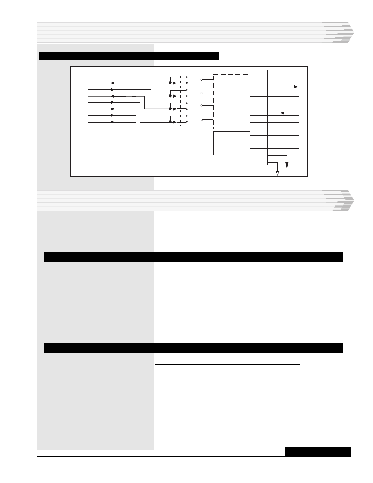
Refer to Fig. 1 for an illustration of the functional schematic.
46022-20-0398<90-00066> PAGE 3
FIG. 1 -FUNCTIONAL SCHEMATIC, 46022-20 MULTIPLE ALARM COMBINER
- BATT
45 +5 VDC
47 +12 VDC
49 -12 VDC
CTS
DCD
DSR
TXD
DTR
RTS
39
43
40
37
41
38
42
D3
D4
D2
D1
53RXD
CA 54
18
55
56
36
DATA
XMT
DATA
RCV
CF
35
17
GND
-
+
-
+
SUBASS'Y
OUT
IN
OUT
IN
OUT
IN
OUT
IN
MODULE
SUASS'Y
POWER
SUPPLY
CIRCUIT DESCRIPTION
INSTALLATION
Before mounting the module in the equipment housing, note
the following information about strapping and subassem-
blies:
STRAPPING
The 46022-20 MAC has strapping points to place the signal
isolation diodes IN or OUT of the circuit (refer to Figs. 1 and 2).
They are normally strapped IN.
If you need to replace a module in the field, strap the replace-
ment unit to match the one you’re replacing or contact Dantel’s
Customer Support Services Department. Set all subassembly
straps or switches in accordance with the practice for that
subassembly.
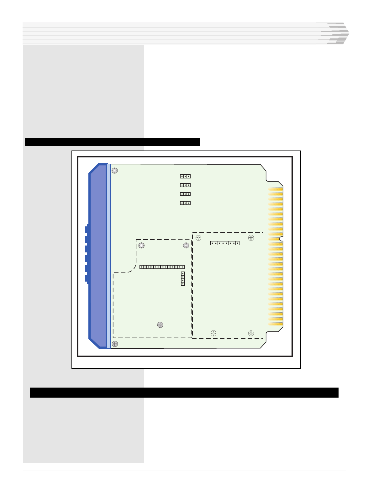
MOUNTING ASUBASSEMBLY
1. To install a subassembly, follow these steps:
♦If there is a hole plug in the front panel of the module, re-
move the plug.
♦Remove the three screws from the subassembly standoffs
and remove any existing subassembly (see Fig. 2).
♦Place the subassembly on the board.
• Insert P4 into J4 and P5 into J5.
CONTINUED . . .
PAGE 4 46022-20-0398 <90-00066>
• Make sure each connector pin goes straight into its socket.
• Make sure the subassembly fits closely on the standoffs.
• Make sure the panel is straight in the opening.
♦Replace the three screws in the standoffs.
♦Refer to the subassembly practice for strapping information.
♦Attach the barcode label for the subassembly to the module
handle.
FIG. 2 - STRAP LOCATIONS, 46022-20 MULTIPLE ALARM COMBINER
J1
81
113
1
4
J5 J4
SUBASSEMBLY
MOUNTING
AREA
MODULE/
SUBASS'Y
POWER SUPPLY
DCDIN
OUT
CTSIN
OUT RXDIN
OUT
OUT DSR
IN
MOUNTING THE MODULE
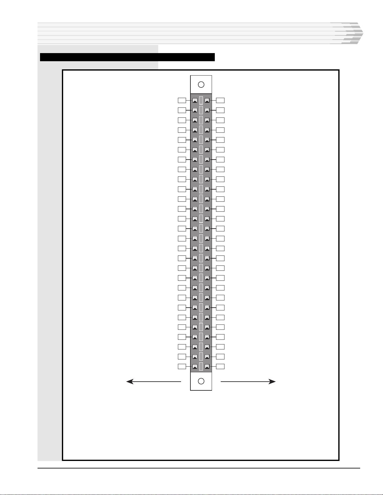
The 56-pin edge connector is normally prewired at the factory.
If you are going to wire the connector, refer to Fig. 3 for module
connector pin wiring assignments. Wire the connector in the
shelf or housing as required.
Slide the module into the equipment housing.
INSTALLATION
46022-20-0398<90-00066> PAGE 5
FIG. 3 - PIN DESIGNATIONS, 46022-20 MULTIPLE ALARM COMBINER
INSTALLATION
56 55
54 53
52 51
50 49
48 47
46 45
44 43
42 41
40 39
38 37
36 35
34 33
32 31
30 29
28 27
26 25
24 23
22 21
20 19
18 17
16 15
14 13
12 11
10 9
87
65
43
21
CIRCUIT SIDE
OF PC BOARD
COMPONENT SIDE
OF PC BOARD
RX- (J5-4. See note below)RX+ (J5-2. See note below)
TX- (J5-5. See note below)TX+ (J5-3. See note below)
-12 VDC Output
+12 VDC Output
+5 VDC Output
CTS (TTL from MAP)
TXD (TTL from MAP)RTS (TTL from MAP)
RXD (TTL from MAP)DCD (TTL from MAP)
DSR (TTL from MAP)DTR (TTL from MAP)
-21 to -56 VDCDIST Output (J4-2. See note below)
GroundDIST Input (J4-4. See note below)
NOTE: The designations shown are for a MAC-20 equipped with a 49013 202
Tone Modem. If using another subassembly, refer to the practice specific to that
subassembly.
PAGE 6 46022-20-0398 <90-00066>
TECHNICAL SPECIFICATIONS
DESCRIPTION
Input Voltage
Input Current *
@ -21 VDC
@ -24 VDC
@ -48 VDC
@ -56 VDC
Heat Dissipation *
@ -21 VDC
@ -24 VDC
@ -48 VDC
@ -56 VDC
Output Voltage
Weight (without subassembly)
Physical Dimensions
Operating Temperature Range
VALUE
-21 to -56 VDC
35 mA
34 mA
35 mA
36 mA
2.6 Btu/Hr
2.8 Btu/Hr
5.8 Btu/Hr
6.9 Btu/Hr
+5 VDC @ 200 mA (pin 45)
+12 VDC @ 20 mA (pin 47)
-12 VDC @ 20 mA (pin 49)
6.5 ounces
1.4" x 6.0" x 5.6"
0° to 55° C.
* NOTE: Input Current and heat dissipation may vary with
output voltage load at pins 45, 47, and 49.

46022-20-0398<90-00066> PAGE 7
NOTES

PAGE 8
8 PAGES 46022-20-0398<90-00066>
LIMITED WARRANTY
The Seller warrants that the standard hardware products sold will be free from defects in material and work-
manship and perform to the Seller’s applicable published specifications for a period of 18 months for hardware,
and 3 months for software, from the date of the original invoice. The liability of the Seller hereunder shall be
limited to replacing or repairing, at its option, any defective products which are returned F.O.B. to the Seller’s
plant, (or, at the Seller’s option, refunding the purchase price of such products). In no case are products to be
returned without first obtaining permission and a customer return authorization number from the Seller. In
no event shall the Seller be liable for any consequential or incidental damages.
Equipment or parts which have been subject to abuse, misuse, accident, alteration, neglect, unauthorized
repair or installation are not covered by warranty. The Seller shall make the final determination as to the
existence and cause of any alleged defect. No warranty is made with respect to custom equipment or products
produced to the Buyer’s specifications except as specifically stated in writing by the Seller in the contract for
such custom equipment.
This warranty is the only warranty made by the Seller with respect to the goods delivered hereunder, and may
be modified or amended only by a written instrument signed by a duly authorized officer of the Seller and
accepted by the Buyer.
Warranty and remedies on products not manufactured by the Seller are in accordance with warranty of the
respective manufacturer. THE SELLER MAKES NO OTHER WARRANTY OF ANY KIND WHATSOEVER,
EXPRESSED OR IMPLIED; AND ALL IMPLIED WARRANTY OF FITNESS FOR A PARTICULAR PUR-
POSE WHICH EXCEEDS THE AFORESAID OBLIGATIONS IS HEREBY DISCLAIMED BY THE SELLER.
INCASE OF DIFFICULTY
If you experience difficulty with this equipment, check the following, as appropriate:
1. Switch settings
2. Signal levels
3. Software configuration
4. Connections between Dantel’s equipment and your equipment.
If there is still a problem, substitute equipment that is known to be good. For additional assistance, call
Dantel’s Technical Field Service Department weekdays, 6 A.M. to 5 P.M. pacific time:
1-800-4DANTEL(1-800-432-6835).
If a thorough checkout shows a piece of equipment has malfunctioned, you may return it to the factory. For
repairs and emergency replacements, obtain a Return Material Authorization (RMA) number from the Cus-
tomer Service Representative at 1-800-4DANTEL (1-800-432-6835).
To ensure expedient processing of your order, provide a purchase order number and shipping and billing
information when requesting an RMA number. Also, when the units are returned to Dantel, include a descrip-
tion of the failure symptoms for each unit returned. Send defective equipment to:
Dantel, Inc. • 2991 North Argyle Avenue • Fresno, California 93727-1388
P.O. Box 55013 • Fresno, CA 93747-5013 Phone (209) 292-1111 Fax (209) 292-9355 http://www.dantel.com
WARRANTY
This manual suits for next models
1
Table of contents
Other Dantel Security System manuals

Dantel
Dantel B23-41071 User manual

Dantel
Dantel A18-05791 Series User manual

Dantel
Dantel 46131 User manual

Dantel
Dantel 46022-30 User manual

Dantel
Dantel B15-00459-02 User manual

Dantel
Dantel RemoteMaster 46132-41 User manual

Dantel
Dantel B23-41070 User manual

Dantel
Dantel B18-05725-03 User manual

Dantel
Dantel A23-41073 User manual

Dantel
Dantel A18-05775 Series User manual


