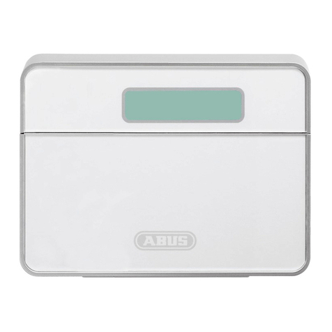
Abus SECVEST User manual

Secvest
User guide
V2.01.08

22
Contents
English
1. Scope of delivery.................................................................................................. 4
2. General ............................................................................................................. 5
2.1 Safety information ........................................................................................... 5
2.2 Information on user guide ................................................................................ 6
2.3 Warranty ....................................................................................................... 6
2.4 Disposal........................................................................................................ 6
2.5 Declaration of conformity.................................................................................. 6
3. Installation example............................................................................................. 8
4. Overview of the system and control panel ................................................................. 9
5. Overview of the numerical keypad........................................................................... 10
6. Secvest display.................................................................................................... 12
7. Menu navigation and operation .............................................................................. 13
8. Arming and disarming the system ........................................................................... 13
8.1 Arming/disarming keys ..................................................................................... 13
8.2 Graphical display of arming/disarming on the display ............................................. 14
8.3 Arming/disarming via the quick arm keys............................................................. 14
8.4 Arming via the user code.................................................................................. 14
8.5 Arming sub-areas ........................................................................................... 16
8.6 Individual sub-areas ....................................................................................... 17
8.7 Internal arming.............................................................................................. 17
8.8 Internal arming via chip key ............................................................................. 18
8.9 Internal arming via remote control..................................................................... 18
8.10 Arming via wireless control panel...................................................................... 18
8.11 Arming via remote control................................................................................ 18
8.12 Arming via chip key........................................................................................ 19
8.13 Arming via delay times.................................................................................... 19
8.14 Preventing arming of the system....................................................................... 20
9. Responding to an alarm........................................................................................ 21
9.1 Alarm types.................................................................................................... 21
9.2 Alarm forwarding............................................................................................ 22
9.2.1 Alarm forwarding via telephone .................................................................. 22
9.2.2 Alarm forwarding to a monitoring station ..................................................... 23
9.2.3 Alarm forwarding via email........................................................................ 23
9.2.4 Alarm forwarding via text message .............................................................. 23
9.2.5 Alarm forwarding in the event of a personal or medical emergency .................... 23
10. User menu ........................................................................................................ 24
10.1 Users.......................................................................................................... 26
10.2 Voice memo ................................................................................................ 27
10.3 Hide zones.................................................................................................. 27
10.5 System conguration..................................................................................... 28
10.5.1 Functions.............................................................................................. 28
10.5.2 Date & time .......................................................................................... 33
10.5.3 Edit outputs.......................................................................................... 34
10.5.4 Remote controls..................................................................................... 35
10.5.5 Volume settings .................................................................................... 35
10.5.6 Web access ........................................................................................... 35
10.5.7 Remote updates..................................................................................... 36
10.5.8 Time schedules active/inactive .................................................................. 36
10.6 Contacts ..................................................................................................... 36
Contents
3
|
22
10.7 Test............................................................................................................ 38
10.7.1 Walk test ............................................................................................... 38
10.7.2 Sirens & sounders ................................................................................... 39
10.7.3 Door locks ............................................................................................. 39
10.7.4 Outputs ................................................................................................ 39
10.7.5 Chip key ............................................................................................... 39
10.7.6 Remote controls ..................................................................................... 40
10.7.7 Emergency buttons .................................................................................. 40
10.7.8 Telephone call ....................................................................................... 40
10.8 Log ........................................................................................................... 40
10.9 Information ................................................................................................ 41
10.9.1 Alarm panel .......................................................................................... 41
10.9.2 Communication ..................................................................................... 42
11. Advanced system operation................................................................................... 44
11.1 Remote control.............................................................................................. 44
11.2 Wireless cylinder lock (“Secvest key”) ................................................................. 44
11.3 Additional door lock (FU7010/7025E) ................................................................... 44
11.4 Operation via telephone.................................................................................. 45
12. Operation via web (app/browser)............................................................................ 46
12.1 Operation via web browser .............................................................................. 46
12.2 Operation via app.......................................................................................... 46
13. Operation via web browser.................................................................................... 47
13.1 Setting the Secvest IP address........................................................................... 48
13.2 Overview of the web interface.......................................................................... 48
13.3 Arming & disarming....................................................................................... 49
13.3.1 Hide zones ........................................................................................... 50
13.4 Additional web interface options...................................................................... 51
13.5 Conguring Secvest “time schedules” ................................................................ 54
13.6 Datasets...................................................................................................... 57
13.7 Exceptions ................................................................................................... 57
14. Terms and denitions.......................................................................................... 58
15. Technical data.................................................................................................... 65
16. Troubleshooting ................................................................................................. 78

44
1. Scope of delivery
Dear Customer,
Thank you for purchasing this SECVEST wireless alarm panel. This device is built with state-of-the-art technology
and it complies with current domestic and European regulations. Conformity has been proven, and all related
certications are available from the manufacturer on request (www.abus.com). To guarantee safe operation,
it is essential that you observe the instructions in this user guide. If you have any questions, please contact
your specialist dealer.
Everything possible has been done to ensure that the content of these instructions is correct. However,
neither the author nor ABUS Security-Center GmbH & Co. KG can be held liable for loss or damage caused by
incorrect or improper installation and operation or failure to observe the safety instructions and warnings.
No liability can be accepted for resulting damage. No part of the product may be changed or modied in
any way. If you do not follow these instructions, your warranty claim becomes invalid. Subject to technical
modications.
© ABUS Security-Center GmbH & Co. KG, 07/2017.
We reserve the right to make changes to this manual without prior notice. This wireless alarm panel is
suitable for use in combination with detectors and sounders for the protection of property, such as your
company, home, garage, garden shed and holiday home.
The following components are included in the scope of delivery for your new Secvest product:
• Wireless alarm panel
• Rechargeable battery
• Quickstart guide
• Mounting material
3 x screws
3 x screw anchors
Battery
Quickstart
guide
1
4
7
*
2
5
8
0
3
6
9
#
3x 3x

5
|
44
2. General
2.1 Safety information
The alarm panel and its connected components must not under any circumstances come into contact with
water, such as in the bathroom. Using the device for purposes other than those described may damage this
product and may also lead to hazards such as short circuits, re or electric shock. The power supply unit is
suitable for operation on the public electrical grid with 230VAC/50Hz. No part of the product may be changed
or modied in any way. Connection to the public electrical grid is subject to your country’s specic regulations.
Please seek information on these regulations before connecting the product to the public grid. Only use the
device for the purpose for which it was built and designed. Any other use is considered unintended.
During the initial set-up of the alarm control panel there is neither a predefined standard installer code
nor a predefined standard administrator code. These need to be individually assigned in the set-up wizard.
Aer the initial start-up please change the default installer name (code = name) as well as the default
administrator name (code = name) to secure user names. When adding users, please make sure you are
careful about how log-in details are handled.
Handling log-in details for your security systems
Basics:
• User names and codes for logging into security systems should be known only by the legal owners and
never given out to unauthorised parties.
• If you have to pass this information on via email, please take care to send the user name and code in
two separate emails.
• User names and codes should be changed regularly.
Standards:
• User names must be at least eight characters long.
• They should ideally contain characters from at least three of the following categories:
uppercase letters, lowercase letters, special characters, and numbers.
• User names should never contain your own name, the name of a family member, your pet, your best
friend or your favourite celebrity, or your hobby or date of birth.
• Avoid using user names and codes that you use on other websites or that could be easily guessed by
others.
• Your user name should not be able to be found in a dictionary and should never be a product name.
• It should not be a conventional series of characters, a repeated pattern or a keyboard pattern, such as
asdfgh or 1234abcd.
• You should avoid only using numbers at the end of your user name or using one of the more typical
special characters (!). ? #) at the beginning or end to compensate for an otherwise simple user name.
• User names and codes should be changed at least every 180days.
• New user names and codes should not be identical to any of the three combinations used before them.
• New user names and codes should dier from user names and codes that have been used before by at
least two characters.
• Macros and scripts should not be used to input user names and codes.
2. General

6
Safety information
2.2 Information on user guide
These instructions contain important installation and operation information. Follow the directions and
instructions in this user manual to ensure safe operation. Store this manual in a safe place for future reference.
This manual constitutes part of the device. If you pass the device on to third parties, please remember to
include this manual.
Note
S/W 2.01.08
This manual relates to soware version 2.01.08 and all other previously published soware versions. All new
features that are only valid from a certain soware version are marked accordingly, e.g. >=2.00.00. All other
features that are valid up to a certain soware version are also marked accordingly, e.g. <2.00.00.
2.3 Warranty
In the event of a warranty claim, the original receipt with the date of purchase and a short written description
of the problem must be supplied with the product. If you discover a defect on your wireless alarm panel
which existed at the time of purchase, contact your dealer directly within the rst two years.
2.4 Disposal
Dispose of the device in accordance with EU Directive 2002/96/EC – WEEE (Waste Electrical and Electronic
Equipment). If you have any questions, please contact the municipal authority responsible for disposal. You
can get information on collection points for waste equipment from your local authority, from local waste
disposal companies or your dealer, for example.
2.5 Declaration of conformity
ABUS Security-Center hereby declares that this type of wireless system FUAA50xxx, complies with RED
Directive 2014/53/EU. The full EU Declaration of Conformity text can be found at: www.abus.com Artikelsuche
FUAA50xxxx/Downloads
The Declaration of Conformity can also be obtained from the following address:
ABUS Security-Center GmbH & Co. KG
Linker Kreuthweg 5, 86444 Ang, GERMANY
2. General

7
|
6

88
3. Installation example
The following provides a simple installation example to show some important basic applications for the
alarm system. The example focuses on a single-family detached home. A representative installation has been
illustrated here, as an example of how it could be implemented in a similar or more advanced form for your
property as well:
The following components are installed in this example:
18 x magnetic contacts at the windows and doors
21 x Secvest key (wireless cylinder lock) at the doors for easy arming/disarming
31 x Secvest alarm panel
42 x motion detectors indoors
51 x wireless outdoor siren under the roof
61 x wireless control panel in the bedroom
71 x info module in the hallway
Perimeter protection: Protects against all possibility of access from outside (windows, doors, etc.).
Analarm is triggered as soon as someone gains access to the property.
Interior protection: Predominantly used as a second line of defence, armed when the occupants of the
building are away so that the perimeter protection acts as the rst alarm and the
interior protection as additional security against intruders.
Internal arming: If you are in the building you can arm just the detectors for the perimeter protection.
The motion detectors indoors remain disabled in this case.
External arming: All available detectors on the premises are enabled.
An overview of all important terms concerning the alarm panel and alarm system can be found in the
appendix under "Terms and denitions".
3. Installation example
1
1
1
1
1
1
1
1
2
3
44
5
7
7

9
|
88
4. Overview of the system and control panel
1
4
7
*
2
5
8
0
3
6
9
#
4. Overview of the system and control panel
1Graphical display for status, menus and additional information
2Keys for menu navigation (see "Menu navigation")
3Quick disarm key for disarming the complete system (code entry required)
4Microphone opening
5Proximity chip key reader area
6Numerical keypad (see following page)
7"Internal arm" key for quick arming of perimeter protection
8Quick arm key for arming the complete system
2
1
3
4
6
5
7
8

10
5. Overview of the numerical keypad
The numerical keypad is used to enter values in certain menus. Letters and special characters are also stored
on the keypad for entering things like user names or email addresses.
1
4
7
*
2
5
8
0
3
6
9
#
The numerical keypad can be used to input various information. For
example, a name can be entered when creating a new user (see "Users").
The letters are not printed on the numerical keypad in order to provide
a better overview during day-to-day operation. Letters are entered
according to the legend provided below.
In addition to data input, numerical keys 1/3, 4/6, 7/9 and the */#
keys are used for quick arming. If the quick arming function using key
combinations is enabled (ask your specialist installation contractor),
both keys of each key pair must be pressed at the same time. The
following alarm options are available:
1
4
7
*
2
5
8
0
3
6
9
#
D, E, F, È, É, Ê, Ë, Ę, 3
J, K, L, Ł, 5
M, N, O, Ø, Ö, Ô,
OE, Ń, Ó, Ñ, 6
G, H, I, Î, Ï, Ğ, İ, 4
A, B, C, Æ, Å, Ä,
À, Â, Ç, Ą, Ć, 2
1
W, X, Y, Z, Ÿ, Ź, Ż, 9
P, Q, R, S, Ś, Ş, 7
, ( ) : . - ! &
@ + _ * # 0
T, U, V, Ü, Ù, Û , 8
5. Overview of the numerical keypad

11
|
10
5. Overview of the numerical keypad
Fire alarm
Press both re alarm keys at the same time to manually trigger a re alarm (for example, if you notice a re
and wish to warn others in the household). The system beeps twice in cycles as a way of providing acoustic
feedback.
Panic alarm
Press both panic keys to trigger a manual panic alarm (for example, if an intruder enters the property while
you are at home). When the keys are pressed, either an acoustic alarm sounds (tone like for an intruder
alarm) or a silent alarm is triggered, depending on your agreement with the specialist installation contractor.
A silent alarm is transmitted to a monitoring station via the integrated dialler, for example.
Medical emergency call
Press both of these keys to trigger a medical emergency call. If there is a potential medical problem (such
as asudden feeling of faintness) this call sends a message to a rescue coordination centre specialised in
handling medical emergencies.
Nursing emergency call
If a vulnerable person resides in your home and requires help, this key combination triggers a related
emergency call. In this case a rhythmic beep sounds from the alarm panel so that other people in the home
are informed that there is a problem.
These and other functions must be set up by a specialist installation contractor as required. The alarms
listed above must be congured by the specialist installation contractor as required when the alarm
panel is installed.
Note:
You are using the touch-front. The backlighting is set to “WHEN active” and the backlighting is dark.
The illumination is rst turned on when a button is pressed (rst touch). No other action results from a
“rst touch”. From the second touch on, the keypad functions as normal.For details, see section 10.5.1
Functions- Backlighting

1212
6. Secvest display
6. Secvest display
1
Voice message This symbol is displayed when a voice message has been recorded (for example,
areminder from another user). Aer the alarm panel has been disarmed the user receives the
following audio message: "You have a message". The message can then be played back and deleted
ifdesired.
2Symbol for activity monitoring. This symbol is only displayed when activity monitoring is active.
This function is used for monitoring vulnerable persons and must be congured by the specialist
installation contractor.
3Display of time and date
4Display of the status of up to 4 sub-areas: open padlock = system disarmed, closed padlock = system
armed, house = internal arming active
5
Error symbol: indicates an alarm, reset, fault etc.
Note:
A "warning triangle" appears at the bottom of the display on the right-hand side if the alarm panel
detects a problem. The explanation (description of the problem) is not shown unless an access level 2
(user) or access level 3 (installer) code is entered.
Aer a valid code has been entered the message appears in plain text (problem, fault, warning, alarm
etc.) The message is hidden again once the user has acknowledged or conrmed it. The notication
disappears automatically aer a one-minute time out.
6Menu symbol: used to access the user menu
1 2 3
6 5 4

13
|
1212
7. Menu navigation and operation | 8. Arming and disarming the system
Cursor control
The Secvest menu is mainly navigated using the cursor keys located below the display:
These keys are used to scroll through the menus and activate specic scenarios when the system is
being armed, amongst other functions. More information is provided in the next chapter, "Arming and
disarming the system".
A manual restart is initiated when the “upward” and “downward” navigation keys are simultaneously
pressed for more than ve seconds. For details, see section 16.1 Manual restart
These keys are used to select menus or symbols, change values and also exit the menus again.
Thefunction of both keys adapts dynamically to the text shown on the display. If, for example, "Menu"
is shown on the le side of the display, press the key below and enter your user code. This brings
you to the user menu which you can exit again by pressing the key.
The cleaning mode is started when the le and right navigation keys are pressed simultaneously.
Fordetails, see section 10.5.1 Functions - Cleaning mode
Note:It is not possible to use the alarm panel during cleaning; this is especially true for the double key
functionality (re, intrusion, medical emergency, care).
8.1 Arm/disarm keys
The arm/disarm keys for the alarm panel are located below the cursor eld. These keys can be used to quickly
and conveniently arm or disarm the alarm panel. Additional arming options are covered in detail below. In
the standard conguration, Secvest is armed on a time delay, meaning it is only armed aer the exit delay
programmed by your specialist installation contractor has expired.
This key is used to start "internal arming". Only the detectors for "perimeter protection" are activated,
so that you are still able to move around the building freely (even if there are motion detectors installed
indoors, for example).
7. Menu navigation and operation
8. Arming and disarming the system

1414
8. Arming and disarming the system
This key is used to quickly arm the complete system. No user code is required for this. Note that when
this key is pressed ALL detectors including those in all sub-areas (if there are any) are activated. This
function will only work if the key has been enabled in consultation with your specialist installation
contractor. This key has no function if it has not been enabled beforehand. If necessary speak to your
installation contractor if this key function is required.
This key is used to disarm the system again. Aer the disarm key is pressed you must enter a valid user
code. The complete system is then disarmed (including all sub-areas).
8.2 Graphical display of arming/disarming on the display
This section contains information on how the arming or disarming of the alarm panel is shown on the
display. This assumes that your system has been congured with just one sub-area. All detectors are therefore
assigned to sub-area1. In this case sub-area1 is the entire premises.
8.3 Arming/disarming via the quick arm keys
1. If the system is disarmed, the display responds as follows: The open padlock
symbol indicates the disarmed status of the alarm panel.
2. If the key is then pressed, the system is completely armed. As mentioned
previously, the system is armed only once the delay time has expired as
programmed by your installation contractor.
3. You should leave the premises within this time delay. The closed padlock
symbol then indicates the armed status of the alarm panel. To disarm the
alarm panel again, simply press the key and enter a valid user code. The
system is then disarmed with the audio message, "The alarm system is
disarmed" and the open padlock symbol visually indicates this status.
This method of arming the system as described here using the quick arm keys is one of the fastest and provides
a representative example of how system arming works in general. The next section provides information on
other ways to arm the system. Not all of these options may be available, as they depend on the conguration
of your system by the specialist installation contractor. If necessary speak to your installation contractor if you
desire a specic method of arming your system.

15|1414
8. Arming and disarming the system
8.4 Arming via the user code
The system can be armed by directly entering a user code.
Thesystemhas either been congured with a 4 or 6-digit user code
inconsultation with your specialist installation contractor.
This code should be changed during commissioning, however. If a new user is added, a separate code is
created for this user. Every user should take note of their individual codes.
1. To arm the system, simply enter a user code. Please note that the "menu"
key is not pressed before entering this code. Otherwise you will be directed
to the user menu, from which you cannot arm the system.
2. Aer the code is entered the "delay time" starts (in the standard conguration
of the system). You should leave the building within this time delay. For this
reason, ensure that sucient time is planned to exit the building. If, for
example, 35s has already passed and you still have to get out the door, there
is not enough time. A false alarm may be triggered, as the opening and
closing of the door takes a bit of time in itself.
3. If the delay time has expired, the system is armed: you have now successfully
armed sub-area1 and can disarm it again by entering a user code.
If a window is still open, for example, when the alarm panel is armed, an error message is displayed.
Correct the error (close the window) and then rearm the alarm panel. If the error cannot be corrected, you
can arm the alarm panel anyway by pressing the "Lock all" key. In this case the alarm panel is armed with
"hidden zones". This means that all open detectors or detectors with faults are ignored during monitoring.
These detectors will not trigger an alarm in this case! These zones only remain hidden until the next time
the system is armed.
1
4
7
*
2
5
8
0
3
6
9
#

16
8. Arming and disarming the system
8.5 Arming sub-areas
In addition to the option of arming a sub-area via a user code, the system can also arm additional sub-areas.
The procedure for this is given here using the user code entry example. This function must be precongured
by your specialist installation contractor.
Aer entering the user code, you are asked to conrm which sub-area(s) you wish to arm. Alternatively you
can also arm the complete system when, for example, you plan on leaving the premises.
1. In our example the alarm panel is divided into 4 sub-areas. These are
displayed as disarmed by the open padlock symbol. First enter your user code
as usual.
2. Once the user code has been entered, the menu changes as follows:
3. Select "Change" and the display changes as shown in the gure on the le.
Click "Done" to arm all sub-areas. The system is now completely armed.
4. If you only wish to arm certain sub-areas, click on "Change" and use the
key to navigate through the four sub-areas until the sub-area you wish to
arm is selected. Click on "Done" to arm the selected sub-area. Repeat the
same procedure to arm other sub-areas.

17|16
8. Arming and disarming the system
8.6 Individual sub-areas
1. If you wish to arm two sub-areas, proceed as follows: enter your user code.
Using the arrow keys, select the two sub-areas to be armed. The
selections are visually highlighted. Set the selected sub-areas to the
open padlock symbol via the "Change" function. Leave the sub-areas you do
not wish to arm "empty". In this case the menu looks like the example given
in the gure on the le.
2. Click on "Done" and system sub-areas 1 & 3 are armed, while sub-areas 2 & 4
remain disarmed. Aer the arming time, the Secvest display then looks like
the example given in the gure on the le.
3. To arm only sub-area 2, repeat the steps as described above. Select the
individual sub-areas, click on "Change" and set the value for the sub-area to
"empty" as shown in the gure. The sub-area to be armed (sub-area2 in this
case) should be set to "active" using the "Change" function. Click on "Done"
to arm just this sub-area.
8.7 Internal arming
In addition to the option of arming the complete system and sub-areas, the system also oers the option
of "internal arming". This type of arming is preferred when occupants are home and wish to arm just the
perimeter of the premises. Certain detectors indoors (such as motion detectors) are disabled so that occupants
can move freely within the building. A practical example here is application in a private home.
The following options are available for internal arming:
Option 1:
Press the key to internally arm the system with just one touch. The quick
arm option must be enabled in advance by the specialist installation contractor.
Option 2:
Enter a user code to arm the system. Click and hold "Change" until the house
symbol appears. Click on "Done" and the system is "internally armed".
You can now move freely around the house even though motion detectors
may be installed. The perimeter of the premises is armed, so that an intruder
attempting to break in from outside triggers an alarm.

18
8. Arming and disarming the system
8.8 Internal arming via chip key
The procedure for internal arming via the chip key is virtually the same as arming the
complete system: Hold the chip key in close proximity to the ABUS logo and swipe
it over the logo briey. A prompt appears, requesting conrmation on the type of
arming required. Click on "Change" as usual and select the house symbol. Click on
"Done" to arm the system internally.
8.9 Internal arming via remote control
On the remote control, the *key is assigned the "internal arm" function as standard.
This symbol is on key2 of the remote control. Press the key and the system is internally
armed. Visual feedback is provided next to the *symbol: brief ashing (green) for
sending the signal, then ashing (red) to indicate successful internal arming.
8.10 Arming via wireless control panel
An additional way of arming the system is provided via the optional wireless control
panel. This arming/disarming option is as similar as possible to the other system
options. Only the operation method is
dierent, as the wireless control panel does
not have a display. Please read the individual operation options in the user manual for
the wireless control panel.
8.11 Arming via remote control
If there is a remote control, you can press the corresponding keys to arm/disarm the
system (all sub-areas are armed/disarmed simultaneously) and internally arm the
system if you as the user are authorised to do so. You can also check the status of
the system. The remote control provides visual system feedback for all entries ("2WAY
function"). For a detailed explanation of the individual functions of your remote
control, please read the user guide for the remote control.

19
|
18
8. Arming and disarming the system
8.12 Arming via chip key
The chip key can be used to completely arm and disarm the wireless alarm panel (or
a sub-area, if there are any) without touching the panel itself. The chip in principle
eliminates the need to enter a code. If you as the user to whom the chip is assigned
are authorised to arm or disarm multiple sub-areas, you must then decide which area
to arm aer you have swiped your chip key. The reader area for the chip key is located
at the height of the ABUS logo. You only have to swipe the chip in the proximity of the
reader area to arm the system – you do not have to touch the housing.
1
4
7
*
2
5
8
0
3
6
9
#
8.13 Arming via delay times
If you enter a code directly on the alarm panel (or via chip key or quick arm keys), the following "problem"
occurs: You must still be able to leave the premises through the doors. If the system were automatically
armed, you would not be able to leave the premises without triggering an alarm, if you have a magnetic
contact on the doors, for example. For this reason there is a "delay time". The delay times are precongured
by your specialist installation contractor.
There are generally two delay times:
• Exit delay
• Entry delay
The exit delay is set to 40s as standard (the time can be adjusted by the specialist installation contractor
according to your needs, however). Following the start of the exit delay, the premises must be le within
this time.
Ensure that all windows and doors etc. are closed rst before activation.

20
8. Arming and disarming the system
Important: if the exit delay has expired and you are still inside the building, your movement, for example,
will trigger an alarm if detected by a motion detector.
The entry delay gives you a sucient timeframe to disarm the system aer opening the doors when the
system is armed. The entry delay should also be programmed in consultation with your specialist installation
contractor. Ideally the entry delay should be as short as possible. If you enter your premises through the
doors, you should hear a pulsed tone. As long as this tone sounds you have time to disarm the system. Disarm
the system using your code (or chip key/disarm key).
Important: if the entry delay expires without the system being disarmed, an intruder alarm is triggered.
8.14 Preventing arming of the system
The alarm panel prevents arming in the following circumstances.
Intrusion detectors (apart from the entrance) are open. Once they have been closed the arming
procedure starts.
A panic button or panic transmitter has been triggered.
The system or a component or detector/zone is showing tampering.
If communication or signalling devices have faults, this
would prevent transmission of notications.
A supervision shutdown in a wireless component
The user can override permissible events (shutdowns).
Aer the start, a continuous tone sounds.
Make your way out of the building and open and close the doors in time.
The continuous tone is replaced by a pulsed tone when the door is opened/closed. It will then return to
acontinuous tone.
The system also allows a special type of exit delay. the system is only armed once the doors are closed.
Theexit delay is therefore exible to allow you to take whatever time you need to get out the door. Speak to
your specialist installation contractor if you desire this type of arming.
Other manuals for SECVEST
5
Table of contents
Other Abus Security System manuals

Abus
Abus TVAC15000 User manual

Abus
Abus CASA10010 User manual

Abus
Abus PLHA10000 User manual

Abus
Abus SHSG10000 Manual

Abus
Abus FU8300 User manual

Abus
Abus FUSG30000 User manual

Abus
Abus TVAC80000B User manual

Abus
Abus Secves FU8007 User manual

Abus
Abus Secoris ESEZ60500 User manual

Abus
Abus TVAC18000A User manual

Abus
Abus COWM300 User manual

Abus
Abus AZ4150 User manual

Abus
Abus FUBE30000 User manual

Abus
Abus SECVEST 868 User manual

Abus
Abus WIRELESS ALARM SYSTEM User manual

Abus
Abus KeyGarage 787 Manual

Abus
Abus AirSecure CO2WM110 User manual

Abus
Abus Terxon LX Instruction Manual

Abus
Abus EYSEO TV7160 User manual

Abus
Abus FUSG50101 Manual