Dantel 46131 User manual

CAUTION
•Install or remove modules from the shelf only when the power is off.
If you install a module in the shelf with the power on, the internal
circuitry may suffer damage and the product warranty will be void.
•Remove and install circuit boards only in a static-safe environment
(use antistatic wrist straps, smocks, footwear, etc.).
•Keep circuit boards in their antistatic bags when they are not in use.
•Do not ship or store circuit boards near strong electrostatic, electromag-
netic, magnetic, or radioactive fields.
•For more complete information on electrostatic discharge safety
precautions, refer to BellcoreTM Technical Reference # TR-NWT-000870.
Copyright 1998 by Dantel, Inc. • Dantel is a registered trademark of Dantel, Inc. • ISO 9001 Registered
Printed in the U.S.A.
INSTALLATION & OPERATION MANUAL
46131-0598 <90-00018>
46131 ALARM
PROCESSING UNIT
(APU)
About this Practice:
This practice has been reissued to:
• Move Troubleshooting section to
inside the
Installation
section.
• Document RS-485 capability on
the receive side of responder ports
1 and 2, and the 8 TBOS ports
(multiple references).
• Update discussion of port activity
monitoring in the
Installation
and
Operation
sections.
Issue date: May 1998
Reissued Practices: Updated and
new content can be identified by a
banner in the right margin.
UPDATED
Table of Contents
Ordering Information ........................................................................... 2
General Description.............................................................................. 2
Circuit Description ............................................................................... 3
Installation............................................................................................ 6
Operation ............................................................................................ 28
Subassembly Installation ................................................................... 31
Circuit Board Replacement ................................................................ 35
Technical Specifications ..................................................................... 36
Warranty ............................................................................................. 38

PAGE 2 46131-0598 <90-00018>
ORDERING INFORMATION
GENERAL DESCRIPTION
The 46131 Alarm Processing Unit (APU) gathers alarm
information from TBOS interrogator ports and local discrete
alarm points. Three responder ports send the information to
alarm reporting equipment in various protocols.
A front panel LED display shows if there are any alarms or
failed TBOS displays.
Wiring is done at the back of the APU.
Before operating the APU, it must be configured. Connect a
dumb terminal or programming paddle to an RS-232 configura-
tion port on the APU. The configuration is backed-up by a
battery.
WARNING: When power is applied to the APU, negative battery voltage is
present at pins 54 and 56 of connector P2 and at any alarm
inputs wired to negative battery. For safety, cover these pins
with protective insulation. Keep the plastic front panel cover
closed during normal operation.
NOTE: This section lists the different options available for this product. To order any of the avail-
able options, contact Dantel Inside Sales through our toll-free number, 1-800-432-6835.
OPTION NUMBER FEATURES
A15-46131-00 Alarm Processing Unit; 32 discrete alarm inputs, 8 control outputs, 8 serial (TBOS) alarm
interrogator ports, two RS-232/422/485 responder ports, one RS-232 configuration port
A15-46131-01 Alarm Processing Unit; 64 discrete alarm inputs, 16 control outpus, 8 serial (TBOS) alarm
interrogator ports, 2 RS-232/422/485 responder ports, 1 RS-232 configuration port
A15-46131-20 Alarm Processing Unit; 32 discrete alarm inputs, 8 control outputs, 8 serial (TBOS) alarm
interrogator ports, two RS-232/422/485 responder ports, one RS-232 configuration port, one
202 modem responder port
A15-46131-21 Alarm Processing Unit; 64 discrete alarm inputs, 16 control outpus, 8 serial (TBOS) alarm
interrogator ports, 2 RS-232/422/485 responder ports, 1 RS-232 configuration port, one 202
modem responder port
A12-46130-00 Expansion Board subassembly; (upgrades -00 option to -01 option, or -20 option to -21 option)
A12-49030-00 202 Modem subassembly; (upgrades -00 option to -20 option, or -01 option to -21 option)
A05-00826-00 Wall-Mount Brackets

46131-0598 <90-00018> PAGE 3
CIRCUIT DESCRIPTION
Fig.1 shows the functional schematic for the 46131 Alarm
Processing Unit.
DISCRETE ALARM INPUTS
All options
The main APU circuit board has 32 discrete alarm inputs that
are optically isolated. Alarms 1-24 each have a single input that
requires a ground to activate the alarm circuitry. Alarms 25-32
each have two inputs, one for negative battery and one for
positive battery.
Options -01 and -21
Alarms 33-64 are on an Expansion Board subassembly that
plugs into the main circuit board. These alarms have a single
input that requires a ground to activate the alarm circuitry.
TBOS ALARM INPUTS
All options
Eight TBOS interrogator ports can poll TBOS equipment for
alarm information. Each port can poll up to 8 displays of infor-
mation for a total of 64 displays on all eight ports. The data
interface standard on each port is RS-422/485.
Switches allow optional termination of the receive inputs.
CONTROL OUTPUTS
All options
The main APU circuit board has eight control outputs. Each
output has two pins wired to normally open relay contacts.
Options -01 and -21
An Expansion Board subassembly has an additional eight
control outputs that can be set with switches for normally open
or normally closed contacts.
UPDATED

PAGE 4 46131-0598 <90-00018>
FIG. 1 - FUNCTIONAL SCHEMATIC
CIRCUIT DESCRIPTION
11
2
33
34 33
34
49
50
51
52
43 37
44
45
46
54
56
53
54
55
TYPICAL INPUT
FOR ALL CIRCUITS
ALARM INPUTS
33 - 64
33K
-BATT
TYPICAL OUTPUT FOR
ALL CIRCUITS
CONTROL OUTPUTS
9 - 16
FRONT PANEL PUSH BUTTONS
AND
SEVEN-SEGMENT DISPLAYS
49
51
52
TD
RD
2
TYPICAL INPUT
FOR ALL CIRCUITS
ALARM INPUTS
1 - 24
33K
-BATT
2
TYPICAL INPUT
FOR ALL CIRCUITS
ALARM INPUTS
25 - 32
33K
1
17
18
TYPICAL OUTPUT FOR
ALL CIRCUITS
CONTROL OUTPUTS
1 - 8
TBOS SERIAL
INTERROGATOR PORTS
1 - 8
182
3
4
TX-
TX+
35
36
39
40
41
42
FUSE ALARM
CIRCUIT
CONFIGURATION PORT
50
53
55
TO
Power Supply
F1
2 AMP GND
-BATT
ACK COS
BACK PANEL
CONNECTOR
OPTICALLY
ISOLATED
INPUT
EXPANSION CARD
MAIN APU CARD
OPTICALLY
ISOLATED
INPUT
OPTICALLY
ISOLATED
INPUT
33K
-BATT
COS
CIRCUIT
OPTICALLY
ISOLATED
INPUT
RESET
X201
P2
P2
P3
P1
P2
P1
P2
P3
P2
P3
S1
RCV
PAD
S1
XMT
PAD
S2
TEST
POINT
XMT
LVL
ADJUST
I.C.
202 MODEM CARD
TYPICAL CIRCUIT
S801
TEST
CD
RESPONDER PORT 4
FUTURE
IBM-COMPATIBLE I/O
CARD
RESPONDER PORT 3
(Options -01 and -21)
(Options -20 and -21)
(All Options)
OUTPUT
TD
1
RD
6
5
9C1 RJ-11
GRN
YEL
BLU 1236
+5 VDC
WHT
RS-422/485 RX-
182
RS-422/485 RX+
RS-422 TX-
RS-422 TX+
RS-232 TD
RS-232 RD
RS-232 GND
RESPONDER PORT 1
X801 S804
S803
S802-3
RS-422/485 RX-
182
RS-422 RX+
RS-422/485TX-
RS-422 TX+
RS-232 TD
RS-232 RD
X802 S806
S805
S802-7
RESPONDER PORT 2
RS-232 GND
MICROPROCESSOR AND
ASSOCIATED CIRCUITRY
CURRENT LIMITER
RS-232 CTS
RS-232 RTS
RS-232 RTS
38
RS-232 CTS
UPDATED

46131-0598 <90-00018> PAGE 5
RESPONDER PORTS
Responder ports send alarm information to alarm reporting
equipment.
All options
Ports 1 and 2 can be either an RS-422/485 or RS-232 interface.
The RS-422/485 receive input can be terminated with 182 ohms
(switch option).
If RS-232 is used on ports 1 or 2, RTS/CTS handshaking can be
used. RTS/CTS handshaking enables communication through an
external modem on ports 1 and 2.
Port 3 is not used.
Options -20 and -21
Port 4 communicates through a optional 202 Modem subassem-
bly that plugs into the main circuit board. The modem operates
as a Bell 202 full-duplex tone modem. It has a data rate of
1200 baud. The modem provides:
♦Test points to measure the transmit and receive signal levels.
♦A potentiometer to adjust the transmit level.
♦An LED to indicate when the carrier signal is present.
The test points and potentiometer are accessible through a
window in the back panel of the APU.
All the responder ports communicate with either DCP, DCPF,
TBOS, or TABS protocol.
CONFIGURATION PORT
To program the APU to operate, connect a programming paddle
or dumb terminal to the RS-232 configuration port. The paddle
plugs into the RJ-11 connector on the front panel. The dumb
terminal connects to C1 on the front panel or at P3 on the back
panel.
LOCAL ALARM AND ACKNOWLEDGEMENT
Wire external audible or visual devices, such as a bells or lights,
to the APU for local alarm monitoring. When there is an alarm,
a relay in the change-of-state (COS) circuit operates the device.
If the alarm device is operating and another alarm occurs, the
relay will pulse once.
Depending on how the APU has been programmed, the relay
returns to its non-alarm state either (1) when all the alarms
clear or (2) when a timer expires after 15 minues. Manually
reset the relay either by applying a ground at the ACK COS
input or by pushing the front panel acknowlege button.
CIRCUIT DESCRIPTION
UPDATED

PAGE 6 46131-0598 <90-00018>
PUSH BUTTONS AND LED DISPLAY
On the front panel are five push buttons and five seven-segment
LED displays. They:
♦Show if there are alarms or failed TBOS displays.
♦Indicate if the TBOS interrogator ports are transmitting and
receiving data.
♦Reset the APU’s microprocessor.
♦Acknowledge alarms.
♦Indicate alarm location.
POWER
The APU operates on -21 to -56 VDC applied at a connector on
the front panel. Power goes through fuse F1 (two amperes) to an
on-board power supply. Power also goes to wire-wrap pins 54
and 56 of connector P2. Use pins 54 and 56, which are limited to
15 mA of current, to provide power to alarm inputs 25-32.
If the fuse fails, the fuse alarm (FA) LED on the front panel
lights. A relay also operates an external alarm.
CIRCUIT DESCRIPTION
INSTALLATION
This section describes those steps necessary to install the
46131 APU. These include Equipment Mounting, Switch and
Strap Settings, Wiring, Configuration, 202 Modem Checkout,
and Troubleshooting.
EQUIPMENT MOUNTING
Brackets on the side of the shelf are installed for mounting the
APU in a 19-inch equipment rack. Refer to Fig. 2 for overall
dimensions of the APU.
♦For mounting in a 23-inch equipment rack, remove the
brackets and reinstall them with the long sides extending out
from the shelf.
♦For flush mounting, remove the brackets and reinstall them
with the mounting ears even with the front of the APU.
♦For wall mounting, replace the brackets with special wall
mount brackets furnished as loose parts. The long side of
each bracket mounts to the APU.
NOTE: The special brackets are supplied only when specifically
ordered. Refer to the Ordering Information section.
WARNING:
When power is applied to
the APU, negative battery
voltage is present at pins 54
and 56 of connector P2 and
at any alarm inputs wired
to negative battery. For
safety, cover these pins
with protective insulation.
Keep the plastic front panel
cover closed during normal
operation.

46131-0598 <90-00018> PAGE 7
FIG. 2 - DIMENSIONS
17.0"
12.5"
5.25"
17.0" 1.0" 3.0"
1.75"
FRONT
TOP
19.0"
23.0"
RECESSED
FRONT PANEL
LOCATION
0.5"
For wall mounting, attach the APU where desired. Hardware is
not supplied.
Refer to Fig. 3 for mounting the APU in an equipment rack and
follow the instructions below. Mounting hardware is supplied in
a bag attached to the side of the shelf.
1. Facing the frame rail, place the APU in the rack in the desired
location. Fasten with three Phillips screws and lockwashers - two
on the right side and one on the lower left side.
2. Install one ESD stud, with lockwasher, in the upper left corner.
3. Tighten the screws and ESD stud snugly. Make sure the stud is
properly grounded to the frame rail.
4. Place an ESD label next to the ESD stud.
5. From the rear of the APU, install the other ESD stud and
lockwasher into the frame next to the APU. Secure tightly, ensur-
ing proper grounding of the ESD stud.
6. Place an ESD label next to the ESD stud.
7. End of equipment mounting.
INSTALLATION

PAGE 8 46131-0598 <90-00018>
FIG. 3 - MOUNTING THE APU
SWITCH AND STRAP SETTINGS
Switches and straps are provided for terminating the receive
ports of the TBOS serial interrogator inputs, setting the electri-
cal interface of the responder ports, and setting the signal levels
of the 202 modem port (-20 and -21 options only).
If necessary, refer to Fig. 1 for a functional schematic showing
the switches and straps.
To set the switches and straps:
1. Open the plastic cover on the front of the APU. Remove the two
screws securing the front panel of the APU.
2. Pull out the printed circuit board to expose the switches and straps.
Refer to Fig. 4 for the locations.
FIG. 4 - SWITCH AND STRAP LOCATIONS
INSTALLATION
WARNING:
Any time the main
board is removed,
take care when re-
installing it to avoid
pinching the power
wires in the rear
connector.
CONTINUED . . .
LOCKWASHERS
LOCKWASHERS
ESD STUD (OPTIONAL)
ESD LABEL FRAME RAIL
ESD LABEL
ESD STUD
STANDARD
SCREW
SHELF
SIDE VIEW FRONT
REAR
ESD
STANDARD
SCREWS STANDARD
SCREWS
STANDARD
SCREWS
ESD LABEL
ESD STUD
SHELF
FRONT VIEW
S803
S804
S805
S806
X801
S801
(TBOS Port
Termination)
S802
(Responder Port
Termination)
X802
1818
Responder
Ports
A = RS-232
B = RS-422/485
Refer to Tables A - E
X201
UP -20 to -40 dBm input
DOWN 0 to -20 dBm input
S1
UP -20 to -40 dBm output
DOWN -1 to -20 dBm output
S2
MODEM CARD
SUBASSEMBLY
EXPANSION CARD
SUBASSEMBLY
S1
A B
S2
A B
S4
A B
S3
A B
OFF A
B
UPDATED

46131-0598 <90-00018> PAGE 9
3. Leave strap X201 open.
4. Refer to Table A to terminate the TBOS receive ports with
182 ohms as needed. The factory settings are terminated.
TABLE A - SWITCH SETTINGS TO TERMINATE TBOS RECEIVE PORTS WITH 182 OHMS (ALL OPTIONS)
NOTE: To change the switches or straps, remove the 202 modem
subassembly (options -20 and -21 only).
5. Refer to Table B to set the switches and straps for Responder
Port 1 (all options). The factory setting is RS-232.
TABLE B - RESPONDER PORT 1 SWITCH AND STRAP SETTINGS (ALL OPTIONS)
INSTALLATION
CONTINUED . . .
DIP SWITCH
S801-1
S801-2
S801-3
S801-4
S801-5
S801-6
S801-7
S801-8
PORT NUMBER
Port 1 Terminated
Port 1 Not Terminated
Port 2 Terminated
Port 2 Not Terminated
Port 3 Terminated
Port 3 Not Terminated
Port 4 Terminated
Port 4 Not Terminated
Port 5 Terminated
Port 5 Not Terminated
Port 6 Terminated
Port 6 Not Terminated
Port 7 Terminated
Port 7 Not Terminated
Port 8 Terminated
Port 8 Not Terminated
POSITION
ON *
OFF
ON *
OFF
ON *
OFF
ON *
OFF
ON *
OFF
ON *
OFF
ON *
OFF
ON *
OFF
* Factory Settings
NOTE: To change the switches, remove the 202 modem subassembly
(options -20 and -21 only). Terminate a port (switch ON) if it is
not used.
* Factory Settings
STRAP OR SWITCH
Strap X801
S803
S804
S802-3
DESCRIPTION
RS-232 Interface
RS-422/485 Interface
RS-232 Interface
RS-422/485 Interface
RS-232 Interface
RS-422/485 Interface
RS-422/485 Receive Terminated
RS-422/485 Receive Not Terminated
POSITION
RS-232 *
RS-422
RS-232 *
RS-422
RS-232 *
RS-422
ON *
OFF
UPDATED
UPDATED

PAGE 10 46131-0598 <90-00018>
6. Refer to Table C to set the switches and straps for Responder
Port 2 (all options.) The factory setting is RS-232.
TABLE C - RESPONDER PORT 2 SWITCH AND STRAP SETTINGS (ALL OPTIONS)
NOTE: To change the switches or straps, remove the 202 modem
subassembly (options -20 and -21 only).
7. Refer to Table D to set the switches for Responder Port 4, the
202 modem port (options -20 and -21). The factory settings are
DOWN.
TABLE D - RESPONDER PORT 4 (MODEM) SWITCH SETTINGS (OPTIONS -20 AND -21)
8. Refer to Table E to set the switches for control outputs 9-16 (op-
tions -01 and -21). The factory settings are Position A.
9. End of Switch and Strap Settings.
TABLE E - CONTROL OUTPUT SWITCH SETTINGS (OPTIONS -01 AND -21)
INSTALLATION
SWITCH POSITION
S1 Position A *
S1 Position B
S1 Position A *
S1 Position B
S1 Position A *
S1 Position B
S1 Position A *
S1 Position B
DESCRIPTION
Control Outputs 9-10 Normally Open
Control Outputs 9-10 Normally Closed
Control Outputs 11-12 Normally Open
Control Outputs 11-12 Normally Closed
Control Outputs 13-14 Normally Open
Control Outputs 13-14 Normally Closed
Control Outputs 15-16 Normally Open
Control Outputs 15-16 Normally Closed
* Factory Settings
* Factory Settings
STRAP OR SWITCH
Strap X802
S805
S806
S802-7
DESCRIPTION
RS-232 Interface
RS-422/485 Interface
RS-232 Interface
RS-422/485 Interface
RS-232 Interface
RS-422/485 Interface
RS-422/485 Receive Terminated
RS-422/485 Receive Not Terminated
POSITION
RS-232 *
RS-422
RS-232 *
RS-422
RS-232 *
RS-422
ON *
OFF
UPDATED
SWITCH POSITION
S1 DOWN *
S1 UP
S2 DOWN *
S2 UP
DESCRIPTION
Receive input level can be between 0 and -20 dBm
Receive input level can be between -20 and -40 dBm
Transmit output adjustable from -1 to -20 dBm
Transmit output adjustable from -20 to -40 dBm
* Factory Settings

46131-0598 <90-00018> PAGE 11
WIRING
CAUTION: To avoid possible damage to the unit, do not make any
connections to the APU if the power is connected and turned
on.
NOTE: When cabling to the APU, leave sufficient slack in the cabling
to permit the internal printed circuit board to slide out from
the front panel (refer to Fig. 5). This allows replacement of the
circuit board without having to rewire the connectors.
If the wire bundle extending out one side of the unit is too thick
to permit closing the plastic front cover, divide the wiring so
some of it comes out the right side of the unit and some of it
extends out the left side of the unit.
FIG. 5 - WIRE SERVICE LOOP
INSTALLATION
CONTINUED . . .
Wire Loop
Wire Loop
Extended
for Service
APU MOUNTED IN RACK
OPERATION
MODE SERVICE
MODE
APU APU
Rack
Rack
Front
Wire Wrap
Pins
Front
Printed
Circuit
Board
Wire Loop
FRONT VIEW SIDE VIEW
Wire connectors P1, P2, and P3:
Refer to the Functional Schematic, Fig. 1, if necessary.
1. Wire connector P1 (refer to Fig. 6) according to Table F and Fig. 7.
Wire P1 to discrete alarm inputs 1-24 (all options) and 33-64 (op-
tions -01 and -21). Wire the inputs to equipment that puts out a
ground signal when there is an alarm. P2 is available for ground
reference.
FIG. 6 - CONNECTOR LOCATIONS FOR WIRING
56
55
ALARM
PROCESSING UNIT
46131
GND
-BATT
READOUTS PUSHBUTTONS
C1
MODEM
FUNCTIONS
RCV
CD
XMT
LVL
AUXILIARY
FUNCTIONS
TST
RCV
XMT
XMT
ABCDE 1234 5 C1 F1 FA F2
P3P2P1
P2 P3P1
56
55
56
55
21
2121
F1 FA F2 -BATT
GND

PAGE 12 46131-0598 <90-00018>
TABLE F - PIN ASSIGNMENTS FOR CONNECTOR P1
INSTALLATION
PIN
1
2
3
4
5
6
7
8
9
10
11
12
13
14
15
16
17
18
19
20
21
22
23
24
25
26
27
28
PIN
29
30
31
32
33
34
35
36
37
38
39
40
41
42
43
44
45
46
47
48
49
50
51
52
53
54
55
56
ASSIGNMENT
Discrete Input 33
Discrete Input 1
Discrete Input 34
Discrete Input 2
Discrete Input 35
Discrete Input 3
Discrete Input 36
Discrete Input 4
Discrete Input 37
Discrete Input 5
Discrete Input 38
Discrete Input 6
Discrete Input 39
Discrete Input 7
Discrete Input 40
Discrete Input 8
Discrete Input 41
Discrete Input 9
Discrete Input 42
Discrete Input 10
Discrete Input 43
Discrete Input 11
Discrete Input 44
Discrete Input 12
Discrete Input 45
Discrete Input 13
Discrete Input 46
Discrete Input 14
ASSIGNMENT
Discrete Input 47
Discrete Input 15
Discrete Input 48
Discrete Input 16
Discrete Input 49
Discrete Input 17
Discrete Input 50
Discrete Input 18
Discrete Input 51
Discrete Input 19
Discrete Input 52
Discrete Input 20
Discrete Input 53
Discrete Input 21
Discrete Input 54
Discrete Input 22
Discrete Input 55
Discrete Input 23
Discrete Input 56
Discrete Input 24
Discrete Input 57
Discrete Input 58
Discrete Input 59
Discrete Input 60
Discrete Input 61
Discrete Input 62
Discrete Input 63
Discrete Input 64
CONTINUED . . .
FIG. 7 - ALARM INPUTS
Ground Return to
Pins P2-53 and 55
or Other Ground Reference
ALARM PROCESSING UNITALARM
SOURCE
ALARM INPUTS 1-24 AND 33-64
APU

46131-0598 <90-00018> PAGE 13
2. Wire connector P2 (refer to Fig. 6) according to Table G.
♦Wire discrete alarm inputs 25-32 (all options). There are two
wires for each input (+ and -). Refer to Fig. 8 for typical wir-
ing circuits.
♦Wire the control relay outputs 1-16 (1-8 for all options, 9-16
for options -01 and -21).
♦Wire the change-of-status (COS) relay, COS acknowledge,
and fuse alarm (all options).
WARNING: When power is applied to the APU, negative battery voltage is
present at pins 54 and 56 of connector P2 and at any alarm
inputs wired to negative battery. For safety, cover these pins
with protective insulation.
TABLE G - PIN ASSIGNMENTS FOR CONNECTOR P2
INSTALLATION
CONTINUED . . .
PIN
1
2
3
4
5
6
7
8
9
10
11
12
13
14
15
16
17
18
19
20
21
22
23
24
25
26
27
28
29
30
PIN
31
32
33
34
35
36
37
38
39
40
41
42
43
44
45
46
47
48
49
50
51
52
53
54
55
56
ASSIGNMENT
Discrete Input 25 (-)
Discrete Input 25 (+)
Discrete Input 26 (-)
Discrete Input 26 (+)
Discrete Input 27 (-)
Discrete Input 27 (+)
Discrete Input 28 (-)
Discrete Input 28 (+)
Discrete Input 29 (-)
Discrete Input 29 (+)
Discrete Input 30 (-)
Discrete Input 30 (+)
Discrete Input 31 (-)
Discrete Input 31 (+)
Discrete Input 32 (-)
Discrete Input 32 (+)
Control Relay Output 1
Control Relay Output 1
Control Relay Output 2
Control Relay Output 2
Control Relay Output 3
Control Relay Output 3
Control Relay Output 4
Control Relay Output 4
Control Relay Output 5
Control Relay Output 5
Control Relay Output 6
Control Relay Output 6
Control Relay Output 7
Control Relay Output 7
ASSIGNMENT
Control Relay Output 8
Control Relay Output 8
Control Relay Output 9
Control Relay Output 9
Control Relay Output 10
Control Relay Output 10
Control Relay Output 11
Control Relay Output 11
Control Relay Output 12
Control Relay Output 12
Control Relay Output 13
Control Relay Output 13
Control Relay Output 14
Control Relay Output 14
Control Relay Output 15
Control Relay Output 15
Control Relay Output 16
Control Relay Output 16
Acknowledge COS
Fuse Alarm (Gnd for alarm)
COS Relay
COS Relay
Ground Out (use for alarm
point ground reference)
Negative Battery Out (for
alarm points 25-32 if battery
reference is needed.)
Ground Out (use for alarm
point ground reference)
Negative Battery Out (for
alarm points 25-32 if battery
reference is needed.)

PAGE 14 46131-0598 <90-00018>
FIG. 8 - TYPICAL CIRCUIT FOR ALARM INPUT
NEGATIVE
INPUT
P2 PINS
54, 56
P2-1
INTERNAL
APU
CIRCUITRY
P2 PINS
53, 55
P2-2
Negative Battery Alarm Input
Typical Circuit forAlarm Input 25-32
(Alarm Input 25 shown)
ALARM
SOURCE
-BATT
P2 PINS
54, 56
P2-1
INTERNAL
APU
CIRCUITRY
P2 PINS
53, 55
P2-2
Ground Alarm Input
Typical Circuit forAlarm Input 25-32
(Alarm Input 25 shown)
ALARM
SOURCE
ALARM PROCESSING UNIT
ALARM PROCESSING UNIT
3. Wire connector P3 (refer to Fig. 6) according to Table H. Wire P3 to
the eight TBOS serial interrogator ports, the three responder ports,
and the configuration port.
The wiring is for all options except for the 202 modem responder
port, which is for options -20 and -21 only.
4. End of this wiring section.
INSTALLATION

46131-0598 <90-00018> PAGE 15
TABLE H - PIN ASSIGNMENTS FOR CONNECTOR P3
INSTALLATION
PIN
1
2
3
4
5
6
7
8
9
10
11
12
13
14
15
16
17
18
19
20
21
22
23
24
25
26
27
28
29
30
31
32
PIN
33
34
35
36
37
38
39
40
41
42
43
44
45
46
47
48
49
50
51
52
53
54
55
56
ASSIGNMENT
TBOS Serial Port 1 RX-
TBOS Serial Port 1 RX+
TBOS Serial Port 1 TX-
TBOS Serial Port 1 TX+
TBOS Serial Port 2 RX-
TBOS Serial Port 2 RX+
TBOS Serial Port 2 TX-
TBOS Serial Port 2 TX+
TBOS Serial Port 3 RX-
TBOS Serial Port 3 RX+
TBOS Serial Port 3 TX-
TBOS Serial Port 3 TX+
TBOS Serial Port 4 RX-
TBOS Serial Port 4 RX+
TBOS Serial Port 4 TX-
TBOS Serial Port 4 TX+
TBOS Serial Port 5 RX-
TBOS Serial Port 5 RX+
TBOS Serial Port 5 TX-
TBOS Serial Port 5 TX+
TBOS Serial Port 6 RX-
TBOS Serial Port 6 RX+
TBOS Serial Port 6 TX-
TBOS Serial Port 6 TX+
TBOS Serial Port 7 RX-
TBOS Serial Port 7 RX+
TBOS Serial Port 7 TX-
TBOS Serial Port 7 TX+
TBOS Serial Port 8 RX-
TBOS Serial Port 8 RX+
TBOS Serial Port 8 TX-
TBOS Serial Port 8 TX+
ASSIGNMENT
Responder Port 1
RS-422/485 RX- or RS-232 RTS
Responder Port 1
RS-422/485 RX+ or RS-232 CTS
Responder Port 1
RS-422 TX- or RS-232 TD
Responder Port 1
RS-422 TX+ or RS-232 RD
Responder Port 1
RS-232 GND
Responder Port 2
RS-232 CTS
Responder Port 2
RS-422/485 RX- or RS-232 RTS
Responder Port 2
RS-422/485 RX+ or RS-232 GND
Responder Port 2
RS-422 TX- or RS-232 TD
Responder Port 2
RS-422 TX+ or RS-232 RD
Responder Port 4
202 Modem RCV+
Responder Port 4
202 Modem RCV-
Responder Port 4
202 Modem XMT+
Responder Port 4
202 Modem XMT-
Not Used
Not Used
Not Used
Not Used
Not Used
Not Used
Configuration Port TXD
Configuration Port RXD
Configuration Port GND
Not Used
UPDATED

PAGE 16 46131-0598 <90-00018>
Wire power
Wire power to the connector between P2 and P3 on the back
panel of the APU (refer to Fig. 6).
1. Insert the negative battery lead in the lower opening on the right
side of the connector. Tighten the connection with the screw on the
front of the connector.
2. Insert the ground lead in the upper opening on the right side of the
connector. Tighten the connection with the screw on the front of the
connector.
CONFIGURATION
The APU must be configured with a programming paddle or
dumb terminal before it will operate properly. The configuration
is battery backed-up.
To use a programming paddle:
Connect the programming paddle to the RJ-11 connector on the
front on the panel.
To use a dumb terminal:
Connect a dumb terminal or computer operating as a dumb
terminal to wire-wrap pins 53, 54 and 55 of connector P3 on the
back panel (refer back to Table H) or connect it to C1 on the
front panel. Refer to Fig. 9 for a drawing showing how connector
C1 is wired. Set up the dumb terminal or computer for 9600
baud, eight data bits and one stop bit.
FIG. 9 - DB9 CONNECTOR WIRING
WARNING: Do not connect a dumb terminal or a computer emulating a
dumb terminal directly to the DB9 connector. The DB9
connector is not a true RS-232 interface when connecting to a
terminal. Pin 9 has +5 VDC on it. A special cable is available
from Dantel that has pin 9 open. You can order the cable by
part number A15-46133-00.
INSTALLATION
(3) Transmit Data (2) Receive Data
(1) NC
(6) NC
(7) Ground
(5) NC
(9) +5 VDC
(4) NC
(8) NC

46131-0598 <90-00018> PAGE 17
To configure the APU remotely:
Connect RJ-11, C1, or wire-wrap pins 53, 54, and 55 of P3 to
your network. Before going to the remote site to configure the
APU, apply power to the APU. Press push button 5 on the front
of the APU until the letters “Pad” appear on the LED display if
you are going to use a programming paddle or the letters “Crt”
appear if you are going to use a dumb terminal. Connect the
programming paddle or dumb terminal at the remote site.
CONFIGURATION USING AHAND-HELD PROGRAMMING PADDLE
1. Apply power to the APU.
2. Configure the paddle to communicate with the APU:
♦Press the SHIFT, CTRL and F1 keys on the paddle at the
same time.
♦Set the baud rate for 9600, data bits for 8, parity for none and
stop bits for 1. Use the F2 key to change the parameter and
the F1 key to change the value.
♦When the values are set, press the F5 key to save them.
3. Configure the ports on the APU:
♦Press push button 5 on the front of the APU until the letters
“Pad” appear on the APU’s LED display.
NOTE: If the APU is being configured from a remote site, press F3 on
the paddle to establish communications with the APU. When
the Main Menu appears on the paddle, press F3 again.
The Main Menu appears on the programming paddle:
F1 - TBOS
F2 - RESP
F3 - EXPB
F4 - XXXX
F5 - HELP
♦Press Help (F5) from the Main Menu and the on-line help
appears on the screen and the function keys described below
are active.
F1 - Moves the Help screen up one line.
F2 - Moves the Help screen down one line.
F5 - Exits the Help screen.
♦Configure the interrogator ports, responder ports, and the
expansion board as described on the next page.
4. End of section.
INSTALLATION

PAGE 18 46131-0598 <90-00018>
CONFIGURING THE INTERROGATOR PORTS
1. From the Main Menu, press F1 (TBOS) to select the Interrogator
Menu. In the Interrogator Menu, the following function keys are
active:
F1 - CHNG. Changes the parameter value.
F2 - NXT PORT. Changes to the next port.
F3 - PREV. Backs up to the previous parameter.
F4 - NEXT. Advances to the next parameter.
F5 - EXIT. Exits the port configuration menu.
2. Use the F1 through F4 keys to configure the eight TBOS ports:
♦Select the desired data rate. Valid entries are 300, 600, 1200,
2400, 4800, and 9600.
♦Set the parity for odd.
♦Set the stop bits for 1.
♦Enable the displays to be used.
NOTE: If TBOS protocol is used on any of the responder ports, enter
the displays in the Interrogator Ports chart of the
Configuration Worksheet (Table I) at the end of this chapter.
This will help you configure the responder ports.
CONFIGURING THE RESPONDER PORTS
1. From the Main Menu, press F2 (RESP) to select the Responder
Menu. The APU has three responder ports that may be configured
independently: ports 1, 2, and 4 (ports 1 and 2 are RS-232/422/485,
port 3 is not used, and port 4 is the 202 modem port).
In the Responder Menu, the following function keys are active:
F1 - CHNG. Changes the parameter value.
F2 - NXT PORT. Changes to the next port.
F3 - PREV. Backs up to the previous parameter.
F4 - NEXT. Advances to the next parameter.
F5 - EXIT. Exits the port configuration menu.
2. Configure each responder port as described below for DCPF, DCP,
TBOS, or TABS protocol.
To configure a responder port for DCPF protocol:
Use the F1 through F4 keys on the paddle to configure the port.
1. Verify the DCPF protocol is selected.
INSTALLATION
UPDATED
CONTINUED . . .

46131-0598 <90-00018> PAGE 19
2. Enter the base (first) address to which the port will respond. Refer
to Fig. 9. Valid entries are 1 - 253. Hold down the F1 key to speed
through the addresses.
3. Enter the desired baud. Valid entries are 300, 600, 1200, 2400,
4800, and 9600. For port 4, the 202 modem port, the baud must be
1200.
4. Verify the parity is set for none.
5. Verify the stop bits are set for 1.
To configure a responder port for DCP protocol:
Use the F1 through F4 keys on the paddle to configure the port.
1. Verify the DCP protocol is selected.
2. Enter the base (first) address to which the port will respond. Refer
to Fig. 10. Valid entries are 1 - 253. Hold down the F1 key to speed
through the addresses.
3. Enter the desired baud. Valid entries are 300, 600, 1200, 2400,
4800, and 9600. For port 4, the 202 modem port, the baud must be
1200.
4. Verify the parity is set for none.
5. Verify the stop bits are set for 1.
NOTE: With DCP protocol, certain address combinations result in
reporting failures. The problem, a loss of synchronization in
the addressing sequence, is inherent in DCP.
Dantel recommends DCPF protocol because it maintains
synchronization.
6. End of section.
FIG. 10 - DCP AND DCPF ALARM REPORTING
Interrogator & Discrete Ports
TBOS Displays 1-32
TBOS Displays 33-64
Discrete Points 1-32
and
Control Points 1-8
Responder Port
DCP / DCPF
Base Address
Base Address + 1
Base Address + 2
TBOS
Ports
5-8
TBOS
Ports
1-4
INSTALLATION

PAGE 20 46131-0598 <90-00018>
To configure a responder port for TBOS protocol:
Use the F1 through F4 keys on the paddle to configure the port.
1. Verify the TBOS protocol is selected.
2. Enter the desired baud. Valid entries are 300, 600, 1200, 2400,
4800, and 9600. For port 4, the 202 modem port, the baud must be
1200.
3. Verify the parity is set for odd.
4. Verify the stop bits are set for 1.
5. Enter the type of alarm information the display will contain. Valid
entries are 1-64 for TBOS displays, null, and discretes. Hold down
the F1 key to speed through the TBOS displays. The null and dis-
crete entries follow the TBOS displays.
Refer to the Configuration Worksheet (Table I) at the end of this
chapter to help configure the port.
To configure a responder port for TABS protocol:
Use the F1 through F4 keys on the paddle to configure the port.
1. Verify the TABS protocol is selected.
2. Enter the desired baud. Valid entries are 300, 600, 1200, 2400,
4800 and 9600. For port 4, the 202 modem port, the baud must be
1200.
3. Enter the address. Valid entries are 0 - 31. Hold down the F1 key to
speed through the addresses.
4. Verify the parity is set for odd.
5. Verify the stop bits are set for 1.
CONFIGURING THE EXPANSION BOARD
Only options -01 and -21 have an Expansion Board subassembly.
1. From the Main Menu, press F3 (EXPB) to select the Expansion
Board Menu.
2. Press F1 to toggle the status. It must be ON for options -01 and -21.
It must be OFF for options -00 and -20.
3. Press F5 to exit the menu.
CONFIGURATION USING ATERMINAL
1. Apply power to the APU and the dumb terminal or computer.
2. Press push button 5 on the front of the APU until the letters “Crt”
appear on the APU’s LED display.
INSTALLATION
CONTINUED . . .
This manual suits for next models
4
Table of contents
Other Dantel Security System manuals
Dantel
Dantel A23-41073-00 User manual

Dantel
Dantel 05202 User manual
Dantel
Dantel RemoteMaster 46132-41 User manual
Dantel
Dantel B15-00459-02 User manual
Dantel
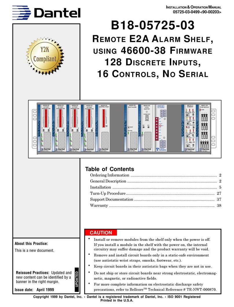
Dantel B18-05725-03 User manual
Dantel
Dantel A18-05791 Series User manual
Dantel
Dantel B23-41070 User manual
Dantel
Dantel A23-41073 User manual
Dantel
Dantel 46022-20 User manual
Dantel
Dantel 46022-12 User manual
