Dantel 05202 User manual
CAUTION
•Install or remove modules from the shelf only when the power is off.
If you install a module in the shelf with the power on, the internal
circuitry may suffer damage and the product warranty will be void.
•Remove and install circuit boards only in a static-safe environment
(use antistatic wrist straps, smocks, footwear, etc.).
•Keep circuit boards in their antistatic bags when they are not in use.
•Do not ship or store circuit boards near strong electrostatic, electromag-
netic, magnetic, or radioactive fields.
•For more complete information on electrostatic discharge safety
precautions, refer to BellcoreTM Technical Reference # TR-NWT-000870.
Copyright 1999 by Dantel, Inc. • Dantel is a registered trademark of Dantel, Inc. • ISO 9001 Registered
Printed in the U.S.A.
INSTALLATION & OPERATION MANUAL
05202-0299 <90-00046>
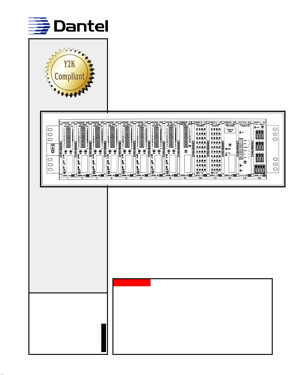
05202
SMALL CENTRAL OFFICE
MASTER ALARM SYSTEM
About this Practice:
This practice has been reissued to:
• Update to reflect Y2K compliance.
Issue date: February 1999
Reissued Practices: Updated and
new content can be identified by a
banner in the right margin.
UPDATED
Table of Contents
Ordering Information ........................................................................... 2
Introduction .......................................................................................... 3
Application Information ....................................................................... 5
Installation............................................................................................ 7
Support Documentation ..................................................................... 43
Warranty ............................................................................................. 46

PAGE 2 05202-0299 <90-00046>
ORDERING INFORMATION
The DJ05202 drawings provide information for ordering the
various components of the Small Central Office Master
Assembly. All the above options include a 256K Status Monitor
w/ keyboard, 41071 Alarm Display Unit, and 3 Terminal Block
Assemblies.
NOTE: This section lists the different options available for this product. To order any of the avail-
able options, contact Dantel Inside Sales through our toll-free number, 1-800-432-6835.
OPTION NUMBER FEATURES
A18-05202-30 256 Discrete Alarm Points, 16 Control Points, 15 TBOS Ports, Writing Shelf
A18-05202-31 128 Discrete Alarm Points, 16 Control Points, 15 TBOS Ports, Writing Shelf
A18-05202-32 128 Discrete Alarm Points, 16 Control Points, 7 TBOS Ports, Writing Shelf
A18-05202-33 96 Discrete Alarm Points, 16 Control Points, 7 TBOS Ports, Writing Shelf
A18-05202-34 160 Discrete Alarm Points, 16 Control Points, 7 TBOS Ports, Writing Shelf
A18-05202-35 256 Discrete Alarm Points, 16 Control Points, 15 TBOS Ports

05202-0299 <90-00046> PAGE 3
INTRODUCTION
This system manual provides information on how to order,
install, and operate the Small Central Office Master Alarm
Assembly. The manual is divided into three main sections, as
outlined below.
Application
A brief description is provided of how the shelf operates and
interfaces with external equipment.
Installation
Follow this section for step-by-step details on installing the
equipment. This section is divided into five parts: equipment
mounting, wiring, switch and strap settings for modules,
turn-up procedure and troubleshooting. The turn-up procedure
provides instructions for getting the system operating.
Support Documentation
This section consists of individual practices on the different
components of the system. The practices provide in-depth
information on the operation of the system components, func-
tional schematics, and technical specifications. The operating
instructions in the practices will provide a useful reference to
the user who needs more details than given in the turn-up
procedure in the Installation section.

PAGE 4 05202-0299 <90-00046>
INTRODUCTION

05202-0299 <90-00046> PAGE 5
APPLICATION INFORMATION
For a functional schematic of the Small Central Office Master
Alarm System Shelf, refer to sheet 2 of the DJ05202 drawing
that follows this page.
Operation of the shelf is controlled by 46020 Multiple Alarm
Processor (MAP) in slot 12. The MAP polls for alarms and issues
commands to operate control points through the Smart MACs in
slots 10 and 11. The 46009 Multiple Alarm Transmitters (MATs)
in slots 1 through 8 accept ground inputs. The 46028 Control
Point Module (CPM) in slot 9 has normally-open relays for
operating controls.
Alarms received by the MAP are reported locally to the 46001
Status Monitor and 41071 Alarm Display Unit.
The MAP also communicates with the alarm center through the
44124 Data Station Termination module is slot 13.
The MAP and Status Monitor require a database to operate.
These databases are configured using a computer running
T/Shell software and downloaded to the modules from the
computer.
The Fuse Module provides fused power to each slot of the shelf.

PAGE 6 05202-0299 <90-00046>
APPLICATION INFORMATION

05202-0299 <90-00046> PAGE 7
INSTALLATION
This section consists of five parts, as explained below.
EQUIPMENT MOUNTING
♦41060 Writing Shelf
♦41071 Alarm Display Unit
♦46001 Status Monitor
♦05202 Equipment Shelf
WIRING
♦A18-05202-XX Block Diagram
♦DT-05202-30 Master Alarm System Interconnection draw-
ings
SWITCH AND STRAP SETTINGS
♦44124-00 Data Channel Termination Module
♦46001-03 Status Monitor
♦46009-02 Multiple Alarm Transmitter
♦46020-41 Multiple Alarm Processor
NOTE: This shelf is Y2K compliant if it is equipped with a
D11-46020-41 or later Multiple Alarm Processor
♦46023-14 Smart Multiple Alarm Combiner
♦46028-01 Control Point Module
♦49008-00 Current Loop Subassembly
♦49013-00 Tone Modem Subassembly
TURN-UP PROCEDURE
TROUBLESHOOTING
UPDATED

PAGE 8 05202-0299 <90-00046>
INSTALLATION

05202-0299 <90-00046> PAGE 9
EQUIPMENT MOUNTING
41060 WRITING SHELF
Tools Required
♦Phillips Screwdriver
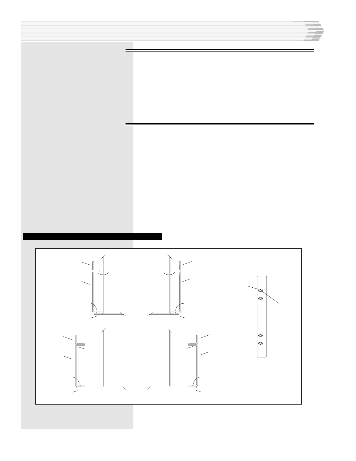
1. The 41060 can be mounted three ways. Refer to Fig. 1. For maxi-
mum stability, the double mounted projection is recommended.
Units come with brackets in the flush mount position. Additional
brackets are included for double mounting.
2. If not mounting flush, remove the slides from the shelf to reposition
the brackets. Fully extend the slide to access the slide mounting
screws from the outside of the shelf. Remove the front bracket
mounting screws by lining them up with the holes in the slide.
Make sure that the bracket positions match the rack before reat-
taching the slides to the shelf.
FIG. 1 - MOUNTING CONFIGURATIONS, 41060 WRITING SHELF
DOUBLE MOUNTED
PROJECTION
(Recommended)
FLUSH MOUNTED
SINGLE MOUNTED
PROJECTION
INSTALLATION
PAGE 10 05202-0299 <90-00046>
41071 ALARM DISPLAY UNIT
1. Mount the light display box using the two mounting holes on the
rear or left side. Use #6 hardware (not provided).
2. Remove the cover from the remote switch unit and mount as re-
quired using the two mounting holes on the rear. Use #6 hardware
(not provided).
3. Refer to the 41071 practice for information on wiring this unit.
46001 STATUS MONITOR
1. Verify that the equipment rack has at least 8 3/4 inches of vertical
clearance (five rack units) to mount the 46001. Mount the 46001 by
placing it in position in the equipment rack and then installing the
bolts shipped with the unit. If extension brackets were ordered,
they must be installed on the equipment rack prior to mounting the
Status Monitor. Refer to Fig. 2.
2. Mount the brackets to the equipment rack using the slotted holes,
with the base located away from the Status Monitor. Mount the
Status Monitor to the brackets using the threaded holes.
3. Install the ESD studs.
FIG. 2 - MOUNTING BRACKET, 46001 STATUS MONITOR
TOP VIEW
19" STATUS MONITOR
SLOTTED
HOLE
SLOTTED
HOLE
EQUIPMENT RACK
MOUNTING BRACKET
THREADED FLANGE
HOLES
EQUIPMENT RACK
MOUNTING BRACKET
THREADED FLANGE
HOLES
EQUIPMENT RACK
MOUNTING BRACKET
THREADED FLANGE
HOLES
SLOTTED
HOLE
EQUIPMENT RACK
MOUNTING BRACKET
THREADED FLANGE
HOLES
SLOTTED
HOLE
SLOTTED
HOLE
SLOTTED
HOLE
SLOTTED
HOLE
SLOTTED
HOLE
THREADED FLANGE
HOLES
SLOTTED
HOLE
TOP VIEW
23" STATUS MONITOR
INSTALLATION
05202-0299 <90-00046> PAGE 11
05202 EQUIPMTENT SHELF
Tools Required:
♦Ohmmeter
♦Phillips screwdriver
1. Visually inspect shelf for obvious damage.
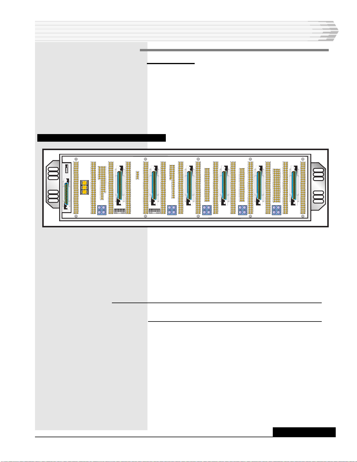
2. Use ohmmeter to check for a short across power input at B (-DC)
and (GND) at the left end of the rear of the shelf (refer to Fig. 3).
FIG. 3 - REAR VIEW OF 05202 EQUIPMENT SHELF
If the shelf is damaged or the power is shorted, the faulty unit is
to be replaced and returned to the factory. For repairs and
emergency replacements, obtain a “Return Material Authoriza-
tion” (RMA) number by calling 1-800-4DANTEL
(1-800-432-6835) and asking for the Customer Return Represen-
tative.
NOTE: To avoid further damage, use the original shipping materials
when returning the shelf.
To ensure expedient processing for your order, provide a pur-
chase order number and shipping and billing information when
requesting an RMA number. Also, when the units are returned
to Dantel, include a description of the failure symptoms for each
unit returned.
Send returned materials to:
Dantel, Inc.
2991 N. Argyle Ave.
Fresno, CA 93727-1388
INSTALLATION
CONTINUED . . .
B
-Batt
Gnd
OPEN OPEN
PAGE 12 05202-0299 <90-00046>
3. With a Phillips screwdriver, mount the shelf in an equipment rack
using the screws and lockwashers supplied in a bag attached to the
side of the shelf.
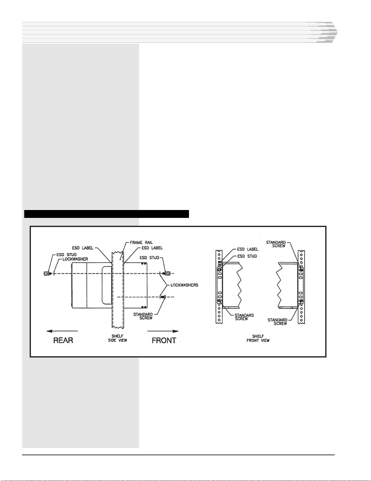
Mounting hardware is supplied in a bag attached to the side of
the shelf. Refer to Figure 4.
Facing the frame rail, place the equipment shelf in the rack in
the desired location. Secure with three Phillips-head screws and
lockwashers - two on the right side, top and bottom, and one on
the lower left side.
4. Install one ESD stud, with lockwasher, in the upper left location.
5. Secure all fasteners tightly, ensuring proper grounding between
ESD stud and frame rail.
6. Place ESD label next to the ESD stud.
7. From the rear of the bay, install the other ESD stud and
lockwasher into the frame rail next to the equipment shelf. Secure
tightly, ensuring proper grounding of the ESD stud. Place ESD
label next to the ESD stud.
FIG. 4 - MOUNTING CONFIGURATION, 41075 400-TYPE MOUNTING
INSTALLATION

05202-0299 <90-00046> PAGE 13
WIRING
Wire the Small Central Office Master Alarm System to external
equipment as required. Use the A18-05202-XX and DT-05202-30
drawings as references for making connections to the Dantel
equipment.
INSTALLATION

PAGE 14 05202-0299 <90-00046>
INSTALLATION
05202-0299 <90-00046> PAGE 15
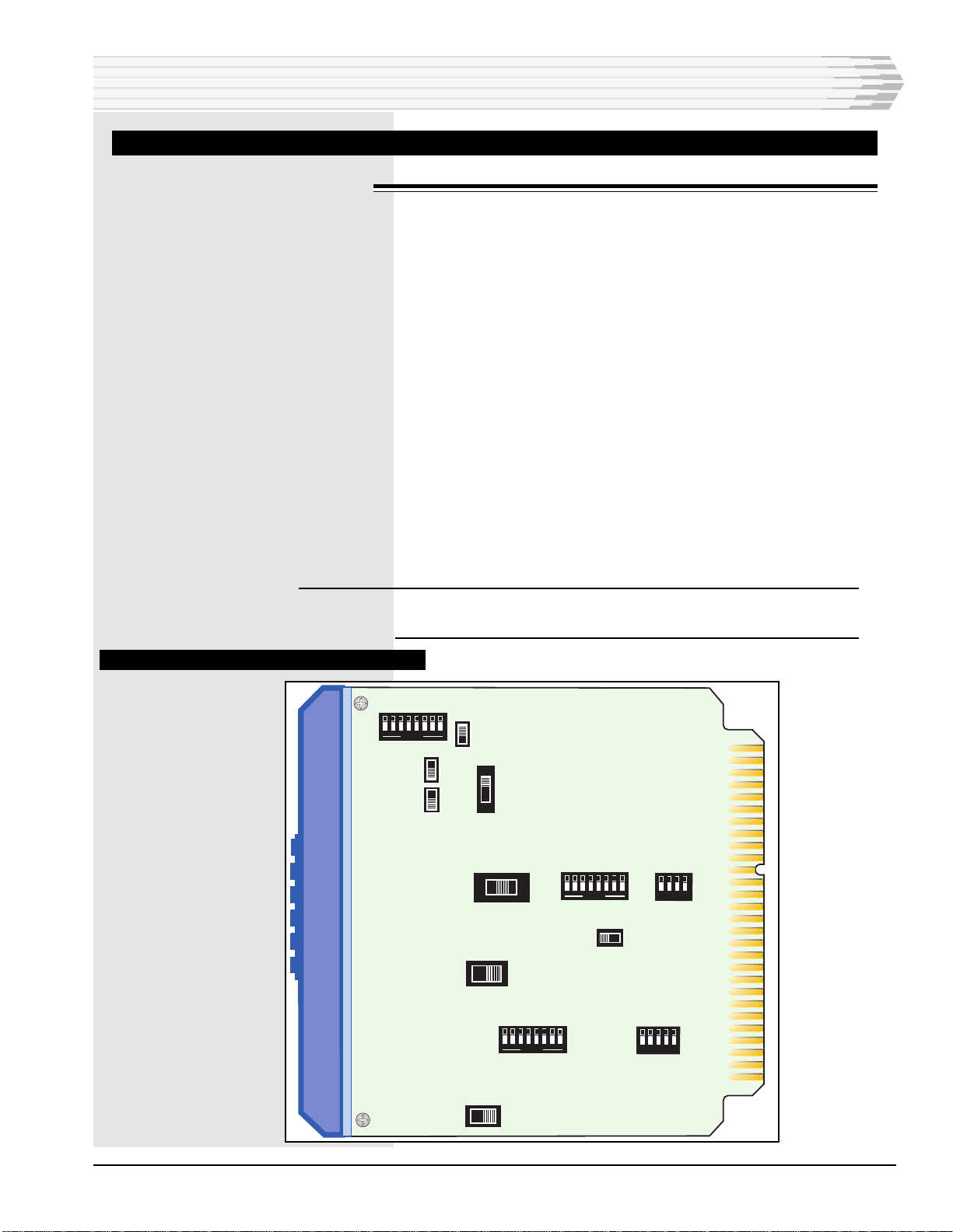
SWITCH AND STRAP SETTINGS
44124 DATA STATION TERMINATION MODULE
Refer to Fig. 6. Recommended switch settings:
S1-1 through S1-8 All OFF
S2 - place in G Position
S3 - place in L position
S4 - place in NOR position
S5 - place in N position
S6 - place in 600 position
S7-1 through S7-8 All OFF
S8-1 through S8-5 All ON (OUT)
S9 - place in BYP position
S10 - place in 4W position
S11-1 through S11-8 All OFF
S12-1 place in 4 position
S12-2 place in ON (unmarked) position
S12-3 place in OFF (disable) position
S12-4 and S12-5 OFF
S13 - place in L position
NOTE: For details about the switch settings, refer to the 44124 Data
Station Termination Module Practice.
FIG. 6 - SWITCH LOCATIONS, 44124 MODUJLE
INSTALLATION
G
L
S2S1
G
L
S3
R
N
S5 S4
NOR
SXT
SC
S6
150 600 1200
S7
HT BW
OUT
IN
S8
S10
4W2W
EQR
S9
BYP
S11
S12
L
S13
G
ON
ON
.1
ON
DTD
81620
MLB
OPEN
12481248
OPEN
NL 1 2 4 8
OPEN
4
.1.2.4.8 1.5 3 6 12
OPEN
.2.4.8 1.5 3 6 12
OPEN

PAGE 16 05202-0299 <90-00046>
46001 STATUS MONITOR
Refer to Fig. 7. Recommended switch and strap settings:
Power Supply and Relay Card
S1 - DOWN (Global)
This switch sets the audible alarm relays to operate on
GLOBAL alarms.
CRT Control Card
S1-1 through S1-8 UP (OFF)
This switch sets the CRT card data rate to 9600 baud.
NOTE: This setting must match the data rate of the GPP printer port.
General Purpose Processor
S1-1 through S1-6 All UP (OFF)
S1-7 and S1-8 DOWN (ON)
S2-1 through S2-8 All UP (OFF)
S3-1 through S3-8 All UP (OFF)
See Fig. 8 for factory strap settings
These switches set the data rate for the master and printer
ports for 9600 baud. The address for the Status Monitor is 1.
Also the switches are set so that neither Global or Local alarms
can be masked.
The data rate for the data port defaults to 1200 baud. The data
rate can be changed to 9600 baud using printer syntax com-
mands.
NOTE: For additional information regarding this and other printer
ssyntax commands, or for further details about switch settings,
refer to the 46001 Status Monitor Practice.
INSTALLATION
05202-0299 <90-00046> PAGE 17
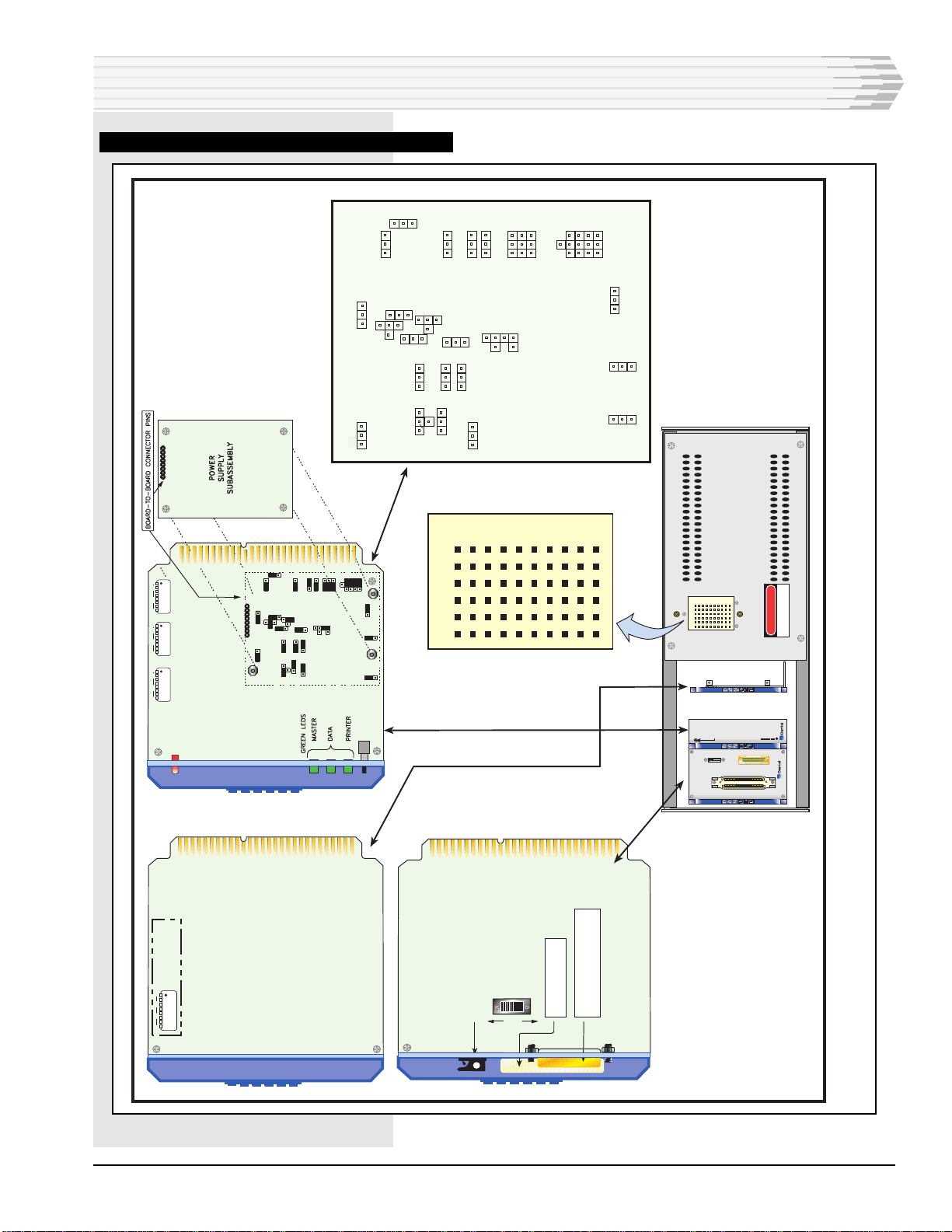
FIG. 7 - BOARD LAYOUT, 46001 STATUS MOLNITOR
INSTALLATION
FEDCBA 1
2
3
4
5
6
7
8
9
10
FEDCBA1
2
3
4
5
6
7
8
9
10
DANGER
HIGH VOLTAGE
POWER SUPPLY
A11-46068-00
F1
J4
J3
TB-1
46062-03
GENERAL
PURPOSE
PROCESSOR
B11-46062-03
MASTER
DATA
PRINTER
RESET
LOW BAT.
STATUS
MONITOR
SUBASSEMBLY
LOW BATTERY
INDICATOR
81
OFF
81
OFF
81
OFF
SW 1 SW 2 SW 3
DOWN = ON
GPP CARD
81
OFF
DIP SWITCH S1
CRT
CONTROLLER
CARD
(B80-00345-00)
FUSE
G/L SWITCH
GLOBAL
J5 DB25 CONNECTOR
(TO PERSONAL COMPUTER)
J3 CONNECTOR
(TO CRT HOUSING)
LOCAL
POWER
SUPPLY
&
RELAY CARD
K3
B1
J2
U1 R2
S2
P2
G2
V2
M1
N1
W1
AA2
Q3
L2
A1
E2
C1
D2
EE1
DD1
I1
X1
X2
Z1
BB1
CC2 T1
H2
F2

PAGE 18 05202-0299 <90-00046>
The GPP Module has been strapped at the factory for RS-232
communications on both the master and data ports. To change
or verify the strap positions the power supply subassembly
board must be removed from the module. This is accomplished
by the following steps:
1. Remove power from the 46001 (if not already removed).
2. Remove the GPP card from the rear of the 46001.
3. Refer to Fig. 8. Carefully remove the power supply subassembly,
exposing the straps located on the main circuit board below the
subassembly.
4. Verify the strapping and make changes as required.
NOTE: Refer to the 46001 Status Monitor Practice for additional
information.
5. Reinstall the power supply subassembly board, insuring that each
pin of the board to board connector is in the proper position. Rein-
stall the module into the 46001 housing.
FIG. 8 - SWITCH AND STRAP LOCATIONS, 46062
INSTALLATION
LOW BATTERY
INDICATOR
81
OFF
81
OFF
81
OFF

05202-0299 <90-00046> PAGE 19
46009 MULTIPLE ALARM TRANSMITTER
Recommended switch and strap settings:
NOTE:Switch settings are the same for all MATs unless specified
otherwise. Refer to Fig. 9 for switch locations and Fig. 10 for
addresses.
S3 - All UP (OFF)
S4 - 1 and 2 UP (OFF)
S4 - 3, 4, and 5 DOWN (ON)
S4 - 6, 7, and 8 UP (OFF)
S5 - See Figure 10
S6 - All UP (OFF)
S301 - 1 DOWN (ON) and 2 UP (OFF)
A/B mini-jumper - A position
These switches set the data rate for the MATs at 1200 baud and
the protocol for DCM. The address is 1 for the MAT in slot 1;
3 for the MAT in slot 2; 5 for the MAT in slot 3 and so on.
NOTE: For additional details about the switch and strap settings,
refer to the 46009 Multiple Alarm Transmitter Practice in the
Appendix.
INSTALLATION

PAGE 20 05202-0299 <90-00046>
113
1
4
J5 J4
SUBASSEMBLY
MOUNTING
AREA
S5
12345678
S4
12345678
S3
8
1234567
MEMORY BOARD SUBASSEMBLY
MOUNTS ON MAIN BOARD OVER S6
21
S301
4 3 2 1
S6
AB
FIG. 9 - SWITCH AND STRAP LOCATIONS, 46009 MODULE
INSTALLATION
This manual suits for next models
6
Table of contents
Other Dantel Security System manuals

Dantel
Dantel 46022-20 User manual

Dantel
Dantel A23-41073-00 User manual

Dantel
Dantel A23-41073 User manual

Dantel
Dantel 46022-12 User manual

Dantel
Dantel B23-41070 User manual

Dantel
Dantel B23-41071 User manual

Dantel
Dantel 46131 User manual

Dantel
Dantel 46022-30 User manual

Dantel
Dantel B18-05725-03 User manual

Dantel
Dantel B15-00459-02 User manual


