Dantel A23-41073-00 User manual

CAUTION
Install or remove modules from the shelf only when the power is off.
If you install a module in the shelf with the power on, the internal
circuitry may suffer damage and the product warranty will be void.
Remove and install circuit boards only in a static-safe environment
(use antistatic wrist straps, smocks, footwear, etc.).
Keep circuit boards in their antistatic bags when they are not in use.
Do not ship or store circuit boards near strong electrostatic, electromag-
netic, magnetic, or radioactive fields.
For more complete information on electrostatic discharge safety
precautions, refer to BellcoreTM Technical Reference #TR-NWT-000870.
Copyright 1999 by Dantel, Inc. • Dantel is a registered trademark of Dantel, Inc. • ISO 9001 Registered
Printed in the U.S.A.
INSTALLATION&OPERATION MANUAL
41072-0299<90-00053>
A23-41072 AISLE
PILOT ALARM UNIT
About this Practice:
This practice has been reissued to:
• Add lamp replacement procedure
to
Operation
section.
Issue date: February 1999
Reissued Practices: Updated and
new content can be identified by a
banner in the right margin.
UPDATED
Table of Contents
Ordering Information ............................................................................ 2
General Description ............................................................................... 2
Circuit Description ................................................................................ 2
Application Information ......................................................................... 4
Installation ............................................................................................ 5
Operation ............................................................................................... 6
Technical Specifications ......................................................................... 7
Warranty ............................................................................................... 8
MIN
MAJ
TEST

PAGE 2 41072-0299<90-00053>
ORDERING INFORMATION
GENERAL DESCRIPTION
The 41072 Aisle Pilot Alarm Unit provides visual alarm
indicators for Dantels 460 Alarm and Control System.
You can wire the unit for critical, major, and minor alarms. The
unit accepts up to 100 ground inputs from the 460 ACS equip-
ment. The inputs are arranged into four groups of 25 to activate
the different alarms.
Critical and major alarms are reported to a MAJ lamp on the
front of the unit. Minor alarms are reported to a MIN lamp on
the front of the unit. Critical, major, and minor alarms also can
be reported to external audible or visual indicating equipment.
Buttons on the front panel test the critical, major, and minor
alarm relays and external alarm indicating devices.
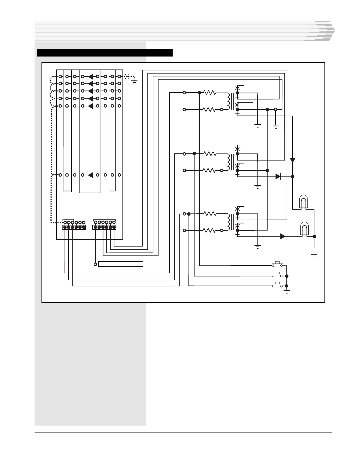
CIRCUIT DESCRIPTION
The schematic diagram for the 41072 Aisle Pilot Alarm Unit is
shown in Fig. 1.
♦Ground alarm inputs are connected to the three relay coils --
K1, K2, and K3 -- through the four banks of isolation diodes.
♦When a relay is energized, the corresponding lamp lights and
activates any external alarm indicating devices connected to
the unit.
♦Each of the relays has a set of contacts for sending remote
alarms.
♦The front panel test buttons provide grounds to operate the
relays and test the front panel lamps and any external alarm
indicating devices.
NOTE: This section lists the different options available for this product. To order any of the avail-
able options, contact Dantel Inside Sales through our toll-free number, 1-800-432-6835.
OPTION NUMBER FEATURES
A23-41072-00 Aisle Pilot Alarm Unit
A23-41076-00 Mounting Bracket
A25-00020-00 Replacement Lamp #48PSB
A25-00021-00 Lens Cap Color Red
A25-00022-00 Lens Cap Color Clear
A25-00023-00 Lens Cap Color Amber
A25-00024-00 Lens Cap Color Green
41072-0299<90-00053> PAGE 3
FIG. 1 - SCHEMATIC, 41072 AISLE PILOT ALARM UNIT
CIRCUIT DESCRIPTION
1
25
TO EXTERNAL
CONNECTION
LOCATIONS
51
26
176 26
51
76
75
50
25 100 50
75
100
TYPICAL
ALARM INPUT
MULTIPLES
P1 P2
K1
K1A
K1BK1C
K3
K3BK3C
K2
K2A
K2BK2C
CRITICAL K1-3
+48 VDC
1
2
3
5
4
6
1.8K OHM
600 OHM
+48 VDC
LP1
LP2
MAJ
MIN
-48VDC
600 OHM
1.8K OHM
1
2
3
5
4
6
1
2
3
5
4
6
600 OHM
1.8K OHM
+48 VDC
+48 VDC
MAJOR K2-3
MINOR K3-3
+48VDC
CRIT
TEST
MAJ
-48 VDC
+48 VDC
-48VDC
MIN
FUSED SOURCE 1 AMP
K1 - A
K2 - A
K3 - A
+48 VDC
K3A

PAGE 4 41072-0299<90-00053>
APPLICATION INFORMATION
The Alarm Display Unit can be installed wherever audible
alarm indicators are needed (for example, at the end of an
equipment aisle).
The 41072 Alarm Display Unit can be used with the following
devices:
MULTIPLE ALARM TRANSMITTERS (MATS):
Inputs to the Alarm Display Unit can come from the A through
D alarm level relay outputs from Dantels 46009 and 46010
Multiple Alarm Transmitters (MATs). Refer to the MAT Practice
for pin-outs.
SUMMARY AUDIBLE ALARM MODULE:
You can tie alarm outputs from the relays of Dantels 46017
Summary Audible Alarm Module (SAAM) to the Alarm Display
Units inputs. The SAAM has two groups of alarms. Each group
has eight inputs but only one output. As a result, the SAAM can
accept only two levels of alarms, which can come from MATs or
Dantels 46020 Multiple Alarm Processor (MAP). To report all
four alarm levels (A, B, C, D) you need two SAAMs. Refer to the
SAAM Practice for pin-outs.
SUMMARY ALARM MODULE:
Dantels 46019 Summary Alarm Module (SAM) has four inputs
to accept the A-D alarm outputs of a MAP. The SAM relay
outputs are wired to the Alarm Display Units inputs. Refer to
the SAM Practice for pin-outs.
CONTROL POINT MODULES:
Dantels 46028 and 46029 Control Point Modules (CPMs) can
echo alarms from MATs. If you use this application, you can
connect the outputs of the CPMs to the Alarm Display Units
inputs for alarm indication. Refer to the CPM Practice for pin-
outs.
STATUS MONITOR:
The audible and visual alarm outputs from Dantels 46001
Status Monitor can be wired to the Alarm Display Units inputs.
Refer to the Status Monitor Practice for pin-outs.
41072-0299<90-00053> PAGE 5
This section describes the steps necessary to install the 41072
Alarm Display Unit.
1. Open the cover.
Open the unit. The hinged access cover requires 3/8" of forward
movement, then a downward rotation of approximately 180
degrees.
2. Mount the unit.
Mount the unit using the four mounting holes in the rear of the
unit. Use #6 hardware (not supplied). If the A16-41076-00
mounting bracket is used, refer to the mounting bracket docu-
mentation.
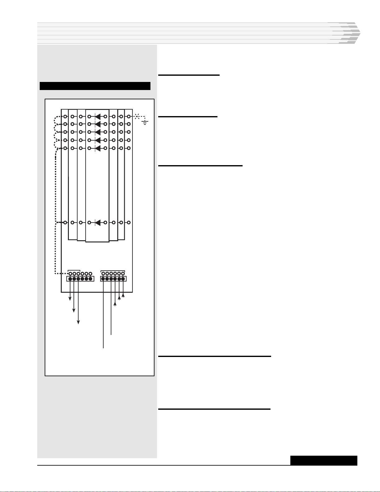
3. Wire the ground inputs.
Refer to Fig. 2.
♦To facilitate the installation of the wire-wrap connections,
temporarily disconnect the connectors P1 and P2.
♦Route the wiring through the large hole in the top of the unit.
♦Wire the ground outputs from the relays of the MATs,
SAAMs, SAMs, or CPMs to the wire-wrap pin terminals on
the diode boards as required. Connect the alarm inputs to the
anode (+) sides of the diodes.
♦Jumper the cathode (-) sides of the diodes that are minor
alarms together.
♦Jumper the cathode (-) sides of the diodes that are major
alarms together.
♦Jumper the cathode (-) sides of the diodes that are critical
alarms together.
♦Wire-wrap the cathode side of the critical alarms to the first
terminal of P1. Wire-wrap the cathode side of the major
alarms to the second terminal of P1. Wire-wrap the cathode
side of the minor alarms to the third terminal of P1.
♦Reconnect P1 and P2.
4. Wire the relay pins to the battery.
♦Wire relay pins K1B, K2B, and K3B to the battery (-48VDC)
pin.
Terminals K1C, K2C, and K3C are used when additional
resistance is required in the operating path of the relays.
5. Wire the relay outputs, if needed.
♦Connect the external audible or visual alarm indicating de-
vices to P2.
♦The external devices must accept a ground input.
INSTALLATION
1
25
TO EXTERNAL
CONNECTION
LOCATIONS
51
26
176 26
51
76
75
50
25 100 50
75
100
TYPICAL
ALARM INPUT
MULTIPLES
P1 P2
FROM MINOR K3-3
FROM MAJOR K2-3
FROM CRITICAL K1-3
+48 VDC
-48 VDC
TO K3 - A
TO K2 - A
TO K1 - A
FIG. 2 - WIRE WRAP PIN LOCATIONS
CONTINUED . . .

PAGE 6 41072-0299<90-00053>
INSTALLATION
6. Wire power.
Connect the power source, with the power turned off, to the unit.
♦Connect -Battery to the -48VDC pin through a 1 amp fuse.
♦Connect Ground to the +48VDC pin.
To verify the operation of the 41072 Aisle Pilot Alarm Unit:
1. Apply power to the unit.
2. Press the Critical Test button on the front panel. Verify that the Ma-
jor light comes on and any external devices connected to K1 operate.
3. Press the Major Test button on the front panel. Verify that the Major
light comes on and any external devices connected to K2 operate.
4. Press the Minor Test button on the front panel. Verify that the Minor
light comes on and any external devices connected to K3 operate.
5. Activate each alarm input that is connected to the unit. In proper
operation, the appropriate light will light.
6. Verify any external equipment connected to the unit functions prop-
erly.
LAMPREPLACEMENTPROCEDURE
To replace the lamps on the 41072 Aisle Pilot Alarm Unit, follow
the procedure below:
1. Slide a knife blade, thin screwdriver, or similiar tool carefully under
the lens between the case and the lens. Approximately 1/8" is suffi-
cient.
2. Using a twisting motion, gently pry up on the lens until it pops off.
3. Pull out the defective lamp.
4. Insert new lamp.
5. Press lens back on.
The lamps are type 48PSB and can be ordered from your local
electronics store or from Dantel using part number A25-00020-00.
OPERATION
NEW TEXT
41072-0299<90-00053> PAGE 7
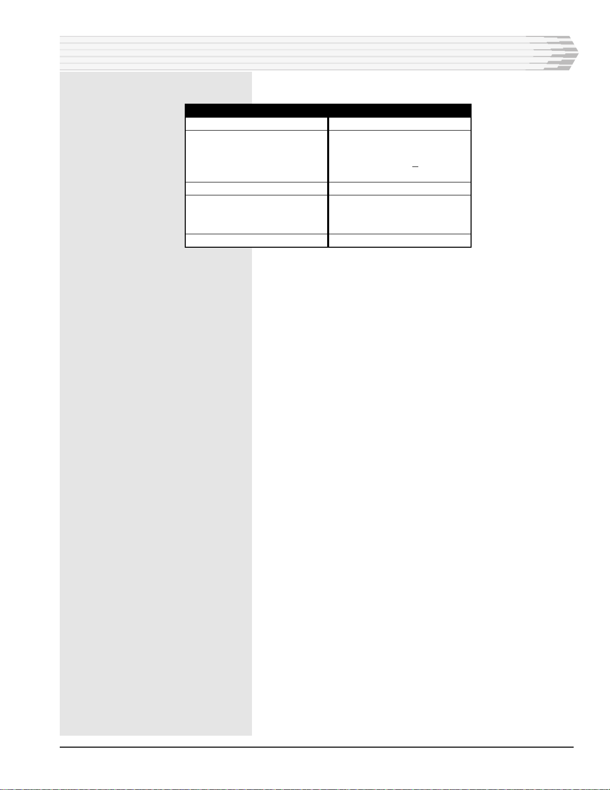
TECHNICAL SPECIFICATIONS
DESCRIPTION
Input Voltage
Relay Coil
Nominal Power
Resistance
Contact Current Rating
Physical Dimensions
Wire Wrap Pin Dimensions
Diameter
Length
Weight
VALUE
-48VDC
518-580 mW
1070 ohms +10%
2 Amps max.
8.0"H x 4.7"D x 3.5"W
0.045", square
0.75"
2.0 lbs

PAGE 8
8PAGES 41072-0299<90-00053>
LIMITED WARRANTY
The Seller warrants that the standard hardware products sold will be free from defects in material and work-
manship and perform to the Sellers applicable published specifications for a period of 18 months for hardware,
and 3 months for software, from the date of the original invoice. The liability of the Seller hereunder shall be
limited to replacing or repairing, at its option, any defective products which are returned F.O.B. to the Sellers
plant, (or, at the Sellers option, refunding the purchase price of such products). In no case are products to be
returned without first obtaining permission and a customer return authorization number from the Seller. In
no event shall the Seller be liable for any consequential or incidental damages.
Equipment or parts which have been subject to abuse, misuse, accident, alteration, neglect, unauthorized
repair or installation are not covered by warranty. The Seller shall make the final determination as to the
existence and cause of any alleged defect. No warranty is made with respect to custom equipment or products
produced to the Buyers specifications except as specifically stated in writing by the Seller in the contract for
such custom equipment.
This warranty is the only warranty made by the Seller with respect to the goods delivered hereunder, and may
be modified or amended only by a written instrument signed by a duly authorized officer of the Seller and
accepted by the Buyer.
Warranty and remedies on products not manufactured by the Seller are in accordance with warranty of the
respective manufacturer. THE SELLER MAKES NO OTHER WARRANTY OF ANY KIND WHATSOEVER,
EXPRESSED OR IMPLIED; AND ALL IMPLIED WARRANTY OF FITNESS FOR A PARTICULAR PUR-
POSE WHICH EXCEEDS THE AFORESAID OBLIGATIONS IS HEREBY DISCLAIMED BY THE SELLER.
INCASE OF DIFFICULTY
If you experience difficulty with this equipment, check the following, as appropriate:
1. Switch settings
2. Signal levels
3. Software configuration
4. Connections between Dantel’s equipment and your equipment.
If there is still a problem, substitute equipment that is known to be good. For additional assistance, call
Dantels Technical Field Service Department weekdays, 6 A.M. to 5 P.M. pacific time:
1-800-4DANTEL(1-800-432-6835).
If a thorough checkout shows a piece of equipment has malfunctioned, you may return it to the factory. For
repairs and emergency replacements, obtain a Return Material Authorization (RMA) number from the Cus-
tomer Service Representative at 1-800-4DANTEL (1-800-432-6835).
To ensure expedient processing of your order, provide a purchase order number and shipping and billing
information when requesting an RMA number. Also, when the units are returned to Dantel, include a descrip-
tion of the failure symptoms for each unit returned. Send defective equipment to:
Dantel, Inc. • 2991 North Argyle Avenue • Fresno, California 93727-1388
P.O. Box 55013 • Fresno, CA 93747-5013 Phone (559) 292-1111 Fax (559) 292-9355 http://www.dantel.com
WARRANTY
This manual suits for next models
1
Table of contents
Other Dantel Security System manuals

Dantel
Dantel 46131 User manual

Dantel
Dantel B23-41070 User manual

Dantel
Dantel RemoteMaster 46132-41 User manual

Dantel
Dantel 46022-30 User manual

Dantel
Dantel 46022-20 User manual

Dantel
Dantel B15-00459-02 User manual

Dantel
Dantel B18-05725-03 User manual

Dantel
Dantel A18-05775 Series User manual

Dantel
Dantel A23-41073 User manual

Dantel
Dantel A18-05791 Series User manual


