Dantel B23-41071 User manual
CAUTION
Install or remove modules from the shelf only when the power is off.
If you install a module in the shelf with the power on, the internal
circuitry may suffer damage and the product warranty will be void.
Remove and install circuit boards only in a static-safe environment
(use antistatic wrist straps, smocks, footwear, etc.).
Keep circuit boards in their antistatic bags when they are not in use.
Do not ship or store circuit boards near strong electrostatic, electromag-
netic, magnetic, or radioactive fields.
For more complete information on electrostatic discharge safety
precautions, refer to BellcoreTM Technical Reference #TR-NWT-000870.
Copyright 1999 by Dantel, Inc. • Dantel is a registered trademark of Dantel, Inc. • ISO 9001 Registered
Printed in the U.S.A.
INSTALLATION&OPERATION MANUAL
41071-1199<90-00037>
B23-41071 ALARM
DISPLAY UNIT
About this Practice:
This practice has been reissued to:
• Minor formating changes. No
change to content.
Issue date: November 1999
Reissued Practices: Updated and
new content can be identified by a
banner in the right margin.
UPDATED
Table of Contents
Ordering Information ........................................................................... 2
General Description.............................................................................. 2
Circuit Description ............................................................................... 3
Application Information ....................................................................... 5
Installation.......................................................................................... 10
Operation ............................................................................................ 13
Technical Specifications ..................................................................... 13
Warranty ............................................................................................. 14

PAGE 2 41071-1199<90-00037>
GENERAL DESCRIPTION
The 41071 Alarm Display Unit provides audible and visual
alarm indicators for Dantels 460 Alarm and Control System.
You can wire the unit for critical, major, and minor alarms. The
unit accepts up to 40 ground inputs from the 460 ACS equip-
ment. The inputs are arranged into three groups to activate the
different alarms.
Two red lamps on the front of the display box indicate critical
and major alarms, and an amber lamp indicates minor alarms.
All alarms also activate an audible alarm, which sounds when
the ON/ACO switch on the remote switch box is in the ON
position. You can change the alarm volume by adjusting a screw
on the right side of the display box.
When the ON/ACO switch is in the ACO (Alarm Cut-Off) posi-
tion, the audible alarm is disabled and the clear lamp lights on
the front of the display box.
A push button on the remote switch box tests the lamps and
audible alarm.
NOTE: This section lists the different options available for this product. To order any of the avail-
able options, contact Dantel Inside Sales through our toll-free number, 1-800-432-6835.
OPTION NUMBER FEATURES
B23-41071-00 Alarm Display Unit
A25-00020-00 Replacement Lamp #48PSB
A25-00021-00 Lens Cap Color Red
A25-00022-00 Lens Cap Color Clear
A25-00023-00 Lens Cap Color Amber
A25-00024-00 Lens Cap Color Green
ORDERING INFORMATION

41071-1199<90-00037> PAGE 3
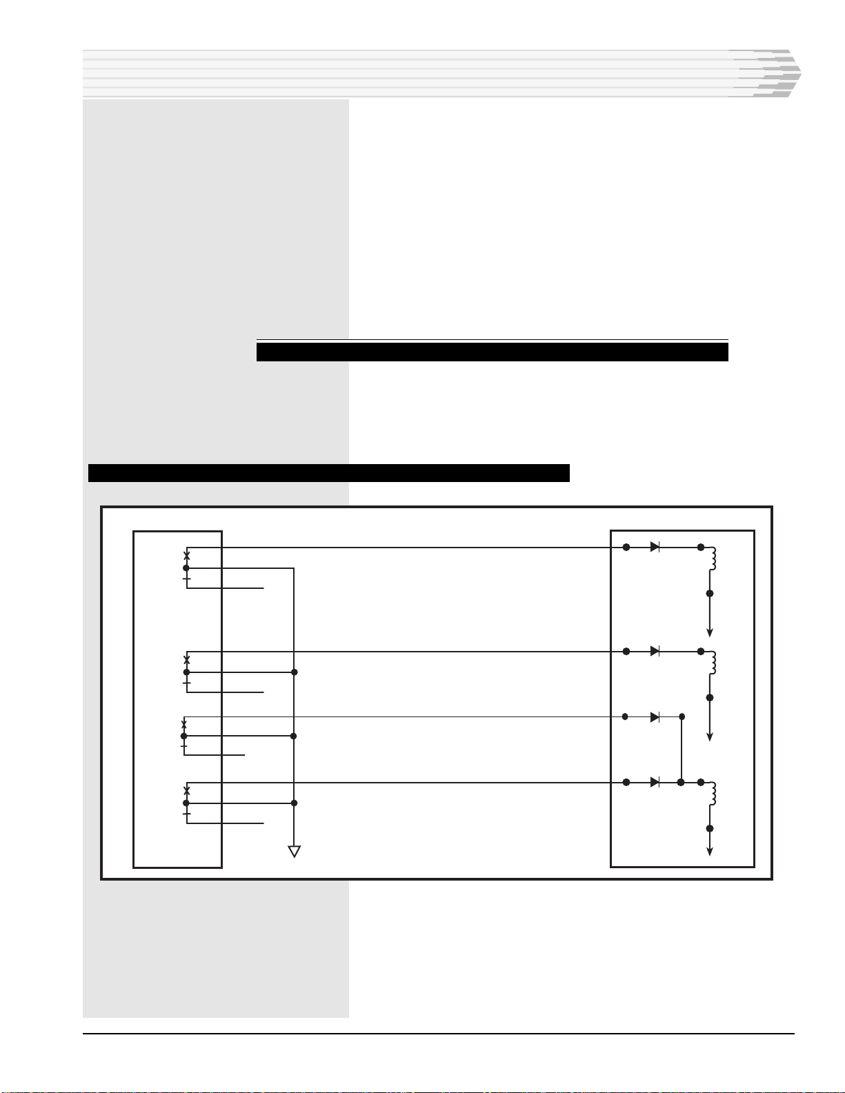
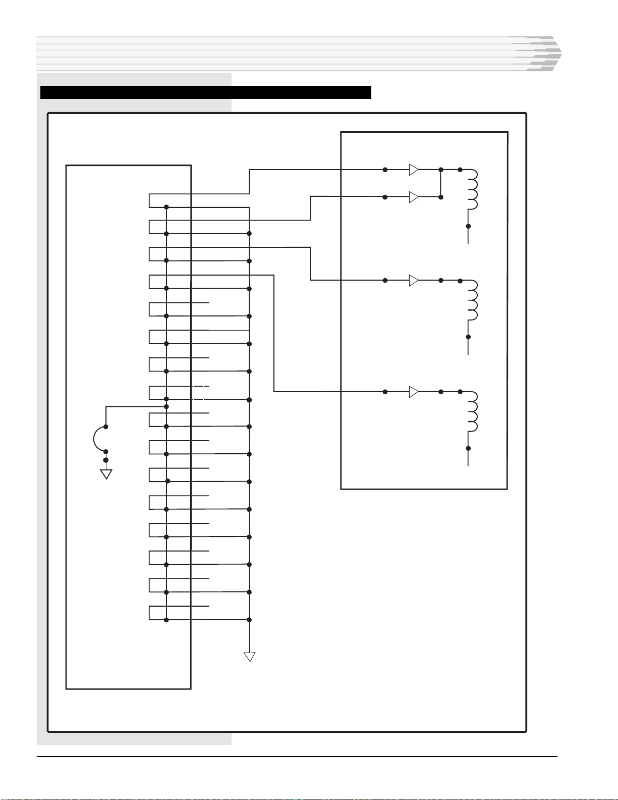
The schematic diagram for the 41071 Alarm Display Unit is
shown in Fig. 1.
♦Ground alarm inputs are connected to the three relay coils,
K1, K2, and K3 through the two banks of isolation diodes.
♦When a relay is energized, the corresponding lamp lights and
the audible alarm sounds.
♦The audible alarm sounds when there is an alarm if the remote
ON/ACO switch is in the ON position. You can change the
alarm volume by adjusting a screw on the right side of the
display box. When the ON/ACO switch is in the ACO (Alarm
Cut-Off) position, the audible alarm is disabled and the clear
lamp lights on the front of the display box.
♦Each of the relays has a set of contacts for sending remote
alarms. A 500-ohm resistor (R5) is furnished to provide optional
strapping for any one of the relay outputs, if required.
♦A push button on the remote switch box tests the operation of
the lamps and audible alarm.
CIRCUIT DESCRIPTION

PAGE 4 41071-1199<90-00037>
CIRCUIT DESCRIPTION
FIG. 1 - SCHEMATIC, 41071 ALARM DISPLAY UNIT
ALARM INPUTS
P.W.B.A.
1
2
3
4
5
6
7
8
9
10
11
12
13
14
15
16
17
18
19
20
1
2
3
4
5
6
7
8
9
10
11
12
13
14
15
16
17
18
19
20
41071-1199<90-00037> PAGE 5
APPLICATION INFORMATION
T
he Alarm Display Unit can be installed wherever audible
and visual alarm indicators are needed (for example, at the end
of an equipment aisle).
The Alarm Display Unit consists of two parts:
♦The alarm display box
♦A remote switch box with a 12-foot cable
You can mount the display box at ceiling level and the switch box
at floor level.
The 41071 Alarm Display Unit can be used with the following
devices:
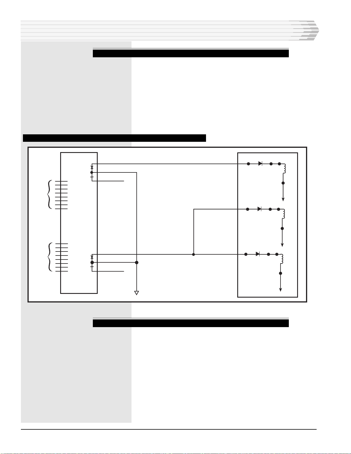
MULTIPLEALARM TRANSMITTERS(MATS):
Inputs to the Alarm Display Unit can come from the A through D
alarm level relay outputs from Dantels 46009 and 46010 Multiple
Alarm Transmitters (MATs). Refer to Fig. 2.
FIG. 2 - TYPICAL RELAY CONNECTIONS, 46009 AND 46010 MULTIPLE ALARM TRANSMITTERS
A
43
41
45
K1A
K1B
B
49
47
51
K2A
K2B
48
52
K3A
K3B
D
50
C
44
42
46
GROUND
46009-03
AND 46010-03
MULTIPLE ALARM
TRANSMITTERS
41071
ALARM
DISPLAY
UNIT -48 VDC
-48 VDC
-48 VDC
PAGE 6 41071-1199<90-00037>
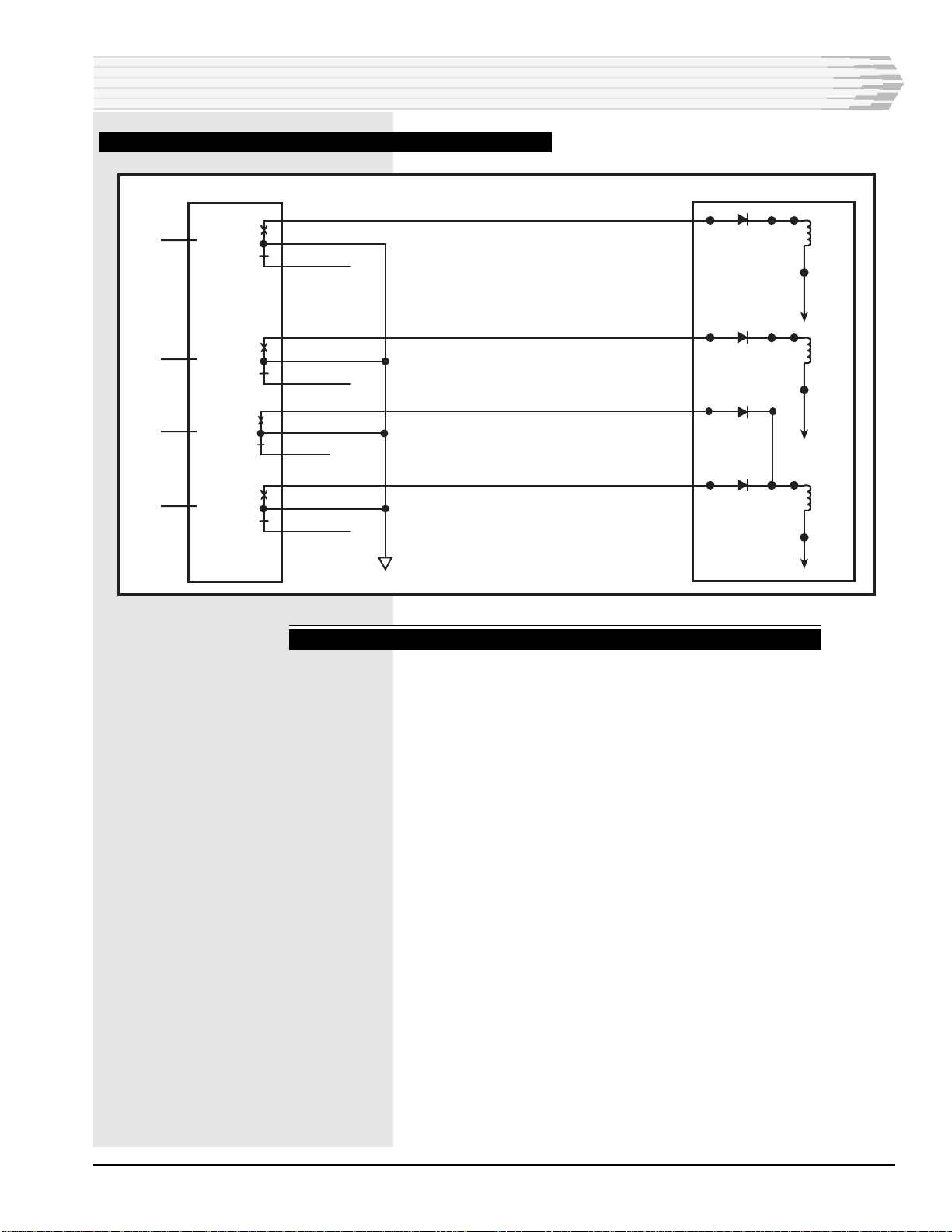
SUMMARYAUDIBLE ALARMMODULE:
You can tie alarm outputs from the relays of Dantels 46017
Summary Audible Alarm Module (SAAM) to the Alarm Display
Units inputs. The SAAM has two groups of alarms. Each group
has eight inputs but only one output. As a result, the SAAM can
accept only two levels of alarms, which can come from MATs or
Dantels 46020 Multiple Alarm Processor (MAP). To report all four
alarm levels (A, B, C, D) you need two SAAMs. Refer to
Fig. 3.
FIG.3 - TYPICAL RELAY CONNECTIONS, 46017SUMMARY AUDIBLE ALARM MODULE
SUMMARYALARM MODULE:
Dantels 46019 Summary Alarm Module (SAM) has four inputs to
accept the A-D alarm outputs of a MAP. The SAM relay outputs
are wired to the Alarm Display Units inputs. Refer to Fig. 4.
APPLICATION INFORMATION
INPUT
FROM
MAT'S
MAP'S
INPUT
FROM
MAT'S
MAP'S
ALARM
GROUP
1
ALARM
GROUP
2
46017
SUMMARY
AUDIBLE
ALARM MODULE
A
43
40
42
14
18
16
GROUND
K1A
K1B
-48
VDC
K2A
K2B
-48
VDC
K2B
K3A
-48
VDC
41071
ALARM
DISPLAY
UNIT
41071-1199<90-00037> PAGE 7
FIG. 4 - TYPICAL RELAY CONNECTIONS,46019 SUMMARY ALARM MODULE
CONTROL POINTMODULES:
Dantels 46028 and 46029 Control Point Modules (CPMs) can
echo alarms from MATs. If you use this application, you can
connect the outputs of the CPMs to the Alarm Display Units
inputs for alarm indication. Refer to Fig. 5.
APPLICATION INFORMATION
A
40
42
39
K1A
K1B
B
44
43
51
K2A
K2B
9
5
K3A
K3B
D
7
C
11
14
13
GROUND
46019 SUMMARY
ALARM MODULE
41071
ALARM
DISPLAY
UNIT -48 VDC
-48 VDC
-48 VDC
INPUT
FROM
MAP LEVEL A
INPUT
FROM
MAP LEVEL B
INPUT
FROM
MAP LEVEL C
INPUT
FROM
MAP LEVEL D
PAGE 8 41071-1199<90-00037>
FIG.5 -TYPICAL RELAY CONNECTIONS, 46028AND 46029 CONTROL POINT MODULES
APPLICATION INFORMATION
-48 VDC
K3B
-48 VDC
K3A
41071
ALARM
DISPLAY
UNIT
K2B
K2A
K1A
K1B
-48 VDC
CONTROL
OUTPUT
46028 AND 46029
CONTROL POINT MODULES
4
3
6
5
8
7
12
11
10
9
14
13
20
19
22
21
24
23
26
25
28
27
30
29
32
31
34
33
1
2
X
1
X
2
X
3
X
4
X
5
X
6
X
7
X
8
X
9
X
10
X
11
X
12
X
13
X
14
X
15
X
16
**
IN
OUT
* BUS CONNECTING EVEN-NUMBERED PINS TOGETHER APPLIES TO 46029 CPM ONLY.
** WIRE EXTERNAL CONNECTIONS TO GROUND ON 46028 ONLY
*
GROUND
16
15

41071-1199<90-00037> PAGE 9
STATUSMONITOR:
The audible and visual alarm outputs from Dantels 46001 Status
Monitor can be wired to the Alarm Display Units inputs. Refer to
Fig. 6.
FIG.6 -TYPICAL RELAY CONNECTIONS,46001 STATUS MONITOR
APPLICATION INFORMATION
GLOBAL
VISUAL
LOCAL
VISUAL
AUDIBLE
-48 VDC
K3B
-48 VDC
K3A
41071
ALARM
DISPLAY
UNIT
K2B
K2A
K1A
K1B
-48 VDC
1C
1D
2E
2F
4A
4B
MINOR
ALARMS
X
X
X
MAJOR
ALARMS
CRITICAL
ALARMS LOCAL
VISUAL
AUDIBLE
GLOBAL
VISUAL
LOCAL
VISUAL
AUDIBLE
46001 Status Monitor
4C
4D
3A
3B
1E
1F
4E
4F
3C
3D
2A
2B
X
X
X
X
X
X
GROUND
GLOBAL
VISUAL
PAGE 10 41071-1199<90-00037>
2. Complete the cable wiring from the switch box.
Wire the cable from the switch box to the display box as follows,
routing the wiring through the small hole in the bottom of the box
(refer to Fig. 7).
♦Blue/white wire to pin 1 of SW1
♦Orange/white wire to pin 2 of SW1
♦White/orange wire to pin 3 of SW1
♦White/green wire to pin 4 of SW1
♦Green/white wire to ground pin (+48V)
♦White/blue wire is not used.
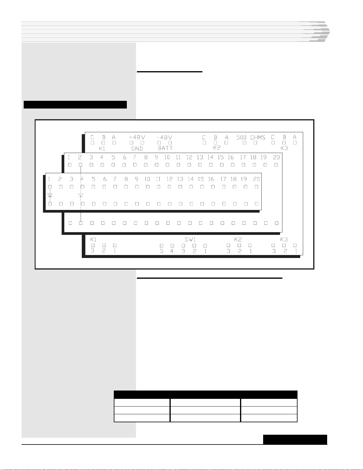
To install the 41071 Alarm Display Unit, refer to Fig. 7, and
follow these steps:
1. Remove the cover.
Take the cover off the display box to gain access to the wire wrap
pins inside.
FIG. 7 - WIRE WRAP PIN LOCATIONS
INSTALLATION
MAJ
MIN
FUNCTION
Critical
Major
Minor
COLOR
Red (top)
Red (middle)
Amber (bottom)
RELAY
K1
K2
K3
CONTINUED . . .

41071-1199<90-00037> PAGE 11
3. Wire the ground outputs.
Each relay is connected to a lamp to indicate an alarm level as
follows:
♦Refer to Fig. 7 for wire-wrap pin locations and Figs. 2-6 for
examples of how the wiring can be done.
♦Route the wiring through the large hole in the top of the dis-
play box.
♦Wire the ground outputs from the relays of the MATs, SAAMs,
SAMs, or CPMs that will be critical alarms to the anode side
(side of diodes with numbers beside them) of the lowest num-
bered diodes on the top and middle PCBs. For example, 12 criti-
cal alarms can be wired to pins 1 through 6 on each PCB.
♦Jumper the cathode (non-numbered) side of these diodes to-
gether.
♦Wire one cathode to K1A on the bottom PCB.
♦Wire the ground outputs from the relays of the MATs, SAAMs,
SAMs, or CPMs that will be major alarms to the anode side
(side of diodes with numbers beside them) of the middle diodes
on the top and middle PCBs.
♦Jumper the cathode (non-numbered) side of these diodes to-
gether.
♦Wire one cathode to K2A on the bottom PCB.
♦Wire the ground outputs from the relays of the MATs, SAAMs,
SAMs, or CPMs that will be minor alarms to the anode side
(side of diodes with numbers beside them) of the lowest num-
bered diodes on the top and middle PCBs.
♦Jumper the cathode (non-numbered) side of these diodes to-
gether.
♦Wire one cathode to K3A on the bottom PCB.
♦If you are using a 46029 CPM, install the relay jumper, on the
CPMs main board, in the IN position.
4. Wire relay pins to the battery.
♦Wire relay pins K1B, K2B, and K3B to the battery (-48V) pin.
Terminals K1C, K2C, and K3C are used when additional resis-
tance is required in the operating path of the relays.
5. Wire the relay outputs, if needed.
♦Wire pins 1, 2, and 3 of K1, K2, and K3 as needed for remote
alarm sending.
There are two pins labeled 500 ohms that are across a 500-ohm
resistor to provide optional strapping to limit the current of one of
the relay outputs, if required.
♦Wire the resistor, if needed, in series with the relay output.
INSTALLATION
CONTINUED . . .

PAGE 12 41071-1199<90-00037>
6. Connect power.
Connect the power source (power off) to the display box:
♦Battery to the -48V pin through a one ampere fuse and ground
to the +48V pin.
7. Mount the display box.
♦Mount the display box before reinstalling the cover. Use the
mounting holes on the back or on the left side of the box. Use #
6 mounting hardware (not supplied).
♦Replace the cover on the display box.
8. Mount the switch box.
♦Remove the cover from the switch box and mount it, using the
mounting holes on the back Use #6 mounting hardware (not
supplied).
♦Replace the cover on the switch box.
CHECKOUT
To verify the operation of the 41071 Alarm Display Unit, follow
these steps.
1. Apply power to the unit. Make sure the ON/ACO switch on the
remote switch box is in the ON position.
2. Push the AUDIO-VISUAL TEST button on the remote switch
box.
In proper operation, the four lamps light, and the audible
alarm sounds. To adjust the volume of the audible alarm, turn
the screw on the right side of the alarm display box.
3. Cause an alarm on each input.
In proper operation, the appropriate lamp lights and the au-
dible alarm sounds.
4. To disable the audible alarm, put the ON/ACO switch in the
ACO position.
In proper operation, the audible alarm does not sound when an
alarm occurs.
LAMPREPLACEMENTPROCEDURE
To replace the lamps on the 41071 Alarm Display Unit, follow the
procedure below:
INSTALLATION
NOTE:
The unit operates at -48 VDC.
For -24 VDC operation, contact
Dantels Field Service Depart-
ment.
41071-1199<90-00037> PAGE 13
INSTALLATION
1. Slide a knife blade, thin screwdriver, or similiar tool carefully under
the lens between the case and the lens. Approximately 1/8" is suffi-
cient.
2. Using a twisting motion, gently pry up on the lens until it pops off.
3. Pull out the defective lamp.
4. Insert new lamp.
5. Press lens back on.
The lamps are type 48PSB and can be ordered from your local
electronics store or from Dantel using part number A25-00020-00.
OPERATION
To make sure the lamps and audible alarm are working, push
the AUDIO-VISUAL TEST button on the remote switch box.
To enable the audible alarm, put the ON/ACO switch on the
remote switch box in the ON position.
To disable the audible alarm, put the ON/ACO switch in the
ACO position.
To adjust the volume of the audible alarm, turn the screw on the
right side of the alarm display box.
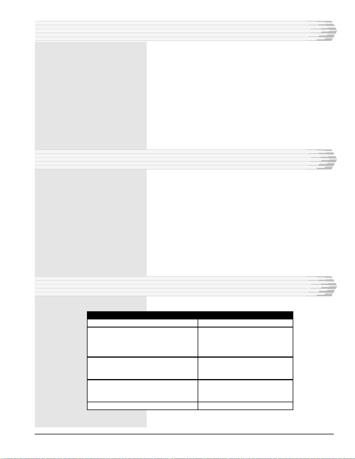
TECHNICAL SPECIFICATIONS
DESCRIPTION
Input Voltage
Relay Coil
Nominal Power
Resistance
Relay Contact Current Rating
Physical Dimensions
Alarm Display Box
Remote Switch Box
Wire Wrap Pin Dimensions
Diameter
Length
Weight
VALUE
-48 VDC
518 - 580 mW
1070 ohms +/-10%
2 Amps (maximum)
7.9"H x 4.7"D x 3.5"W
2.6"H x 1.4"D x 2"W
0.045" square
3/4"
2 lbs.

PAGE 14
14 PAGES 41071-1199<90-00037>
LIMITED WARRANTY
The Seller warrants that the standard hardware products sold will be free from defects in material and work-
manship and perform to the Sellers applicable published specifications for a period of 18 months for hardware,
and 3 months for software, from the date of the original invoice. The liability of the Seller hereunder shall be
limited to replacing or repairing, at its option, any defective products which are returned F.O.B. to the Sellers
plant, (or, at the Sellers option, refunding the purchase price of such products). In no case are products to be
returned without first obtaining permission and a customer return authorization number from the Seller. In
no event shall the Seller be liable for any consequential or incidental damages.
Equipment or parts which have been subject to abuse, misuse, accident, alteration, neglect, unauthorized
repair or installation are not covered by warranty. The Seller shall make the final determination as to the
existence and cause of any alleged defect. No warranty is made with respect to custom equipment or products
produced to the Buyers specifications except as specifically stated in writing by the Seller in the contract for
such custom equipment.
This warranty is the only warranty made by the Seller with respect to the goods delivered hereunder, and may
be modified or amended only by a written instrument signed by a duly authorized officer of the Seller and
accepted by the Buyer.
Warranty and remedies on products not manufactured by the Seller are in accordance with warranty of the
respective manufacturer. THE SELLER MAKES NO OTHER WARRANTY OF ANY KIND WHATSOEVER,
EXPRESSED OR IMPLIED; AND ALL IMPLIED WARRANTY OF FITNESS FOR A PARTICULAR PUR-
POSE WHICH EXCEEDS THE AFORESAID OBLIGATIONS IS HEREBY DISCLAIMED BY THE SELLER.
INCASE OF DIFFICULTY
If you experience difficulty with this equipment, check the following, as appropriate:
1. Switch settings
2. Signal levels
3. Software configuration
4. Connections between Dantel’s equipment and your equipment.
If there is still a problem, substitute equipment that is known to be good. For additional assistance, call
Dantels Technical Field Service Department weekdays, 6 A.M. to 5 P.M. pacific time:
1-800-4DANTEL(1-800-432-6835).
If a thorough checkout shows a piece of equipment has malfunctioned, you may return it to the factory. For
repairs and emergency replacements, obtain a Return Material Authorization (RMA) number from the Cus-
tomer Service Representative at 1-800-4DANTEL (1-800-432-6835).
To ensure expedient processing of your order, provide a purchase order number and shipping and billing
information when requesting an RMA number. Also, when the units are returned to Dantel, include a descrip-
tion of the failure symptoms for each unit returned. Send defective equipment to:
Dantel, Inc. • 2991 North Argyle Avenue • Fresno, California 93727-1388
P.O. Box 55013 • Fresno, CA 93747-5013 Phone (559) 292-1111 Fax (559) 292-9355 http://www.dantel.com
WARRANTY
This manual suits for next models
1
Table of contents
Other Dantel Security System manuals

Dantel
Dantel RemoteMaster 46132-41 User manual

Dantel
Dantel A23-41073 User manual

Dantel
Dantel 46022-30 User manual

Dantel
Dantel B18-05725-03 User manual

Dantel
Dantel 46022-12 User manual

Dantel
Dantel B23-41070 User manual

Dantel
Dantel 46131 User manual

Dantel
Dantel 46022-20 User manual

Dantel
Dantel 05202 User manual

Dantel
Dantel A18-05791 Series User manual


Popular Security System manuals by other brands

Philips
Philips AutoDome TC700 Series user manual

Tigersecu
Tigersecu Super HD 2MP & 5MP 302 Series user manual

LaserShield
LaserShield Instant Security System quick start guide

Bluvision
Bluvision Mini-Mini user guide

DSC
DSC LCD5501Z installation instructions

COLUMBIA BOAT ALARM
COLUMBIA BOAT ALARM 411 owner's manual


