Dantel RemoteMaster 46132-41 User manual

CAUTION
Install or remove modules from the shelf only when the power is off.
If you install a module in the shelf with the power on, the internal
circuitry may suffer damage and the product warranty will be void.
Remove and install circuit boards only in a static-safe environment
(use antistatic wrist straps, smocks, footwear, etc.).
Keep circuit boards in their antistatic bags when they are not in use.
Do not ship or store circuit boards near strong electrostatic, electromag-
netic, magnetic, or radioactive fields.
For more complete information on electrostatic discharge safety
precautions, refer to BellcoreTM Technical Reference #TR-NWT-000870.
Copyright 2000 by Dantel, Inc. • Dantel is a registered trademark of Dantel, Inc. • ISO 9001 Registered
Printed in the U.S.A.
INSTALLATION&OPERATION MANUAL
46132-41-0800<90-00209>>
46132-41
REMOTEMASTER
Issue date: August 2000
Reissued Practices: Updated and
new content can be identified by a
banner in the right margin.
UPDATED
Table of Contents
Ordering Information ............................................................................ 2
General Description ............................................................................... 2
Circuit Description ................................................................................ 3
Standard Installation ............................................................................. 7
Custom Installation ............................................................................. 18
Custom Configuration ......................................................................... 29
Operation ............................................................................................. 38
Circuit Board Replacement .................................................................. 42
Technical Specifications ....................................................................... 44
Warranty ............................................................................................. 46
88888
C1
RemoteMaster
ABCDE
12345
FA
FUSE
88888
About this Practice:
This practice has been reissued to:
• Emphasize that RS-422 is de-
signed for point-to-point commu-
nication and RS-485 is for multi-
point communication.

PAGE 2 46132-41-0800<90-00209>>
NOTE: This section lists the different options available for this product. To order any of the avail-
able options, contact Dantel Inside Sales through our toll-free number, 1-800-432-6835.
OPTION NUMBER FEATURES
B15-46132-41
RemoteMaster
; 64 discrete alarm inputs, 8 control outputs, 2 serial (TBOS) alarm interrogator
ports, 2 RS-232/422/485 responder ports, 1 RS-232 configuration port
A05-00826-00 Wall-Mount Brackets
ORDERING INFORMATION
The 46132-41 RemoteMaster is a master alarm system
primarily intended for small sites. The RemoteMaster
gathers alarm information from 64 ground-activated discrete
alarm inputs. In addition, 8 on-board relays are available for use
as controls and two serial ports interrogate TBOS equipment.
All this alarm information is gathered and reported to two
responder ports which send that information towards your
Alarm Center.
A front panel LED display reports port status and alarm infor-
mation. On-site configuration is quick and simple. The 46132-41
RemoteMaster differs from the other RemoteMasters:
♦Defaults to TABS protocol on its two responder ports
♦Front panel configurable for TABS address (0-31)
♦New backplane makes interconnection easier
♦New power connections allow redundent power supplies
ABOUT THIS MANUAL
This manual is presented in two parts, Standard Installation
and Custom Installation/Custom Configuration.
Standard Installation
Use this section if your application requires a TABS responder
and discrete alarm reporting only. The 46132-41 RemoteMaster
is factory-configured for:
♦TABS output
♦2400 baud, odd parity, 1 stop bit, 8 bit word length, RS-422
♦Discrete alarm gathering only
All that remains is to mount the unit in the rack, wire the
required alarms and responder ports and, from the front panel,
set the TABS address.
GENERAL DESCRIPTION

46132-41-0800<90-00209>> PAGE 3
Fig.1 shows the functional schematic for the RemoteMaster.
DISCRETE ALARM INPUTS
The RemoteMaster circuit board has 64 discrete alarm inputs
that are optically isolated. Alarms 1-24 and 33-64 each have a
single input that requires a ground to activate the alarm cir-
cuitry. Alarms 25-32 each have two inputs, one for negative
battery (factory-wired) and one for ground.
TBOS ALARM INPUTS
Two TBOS interrogator ports poll TBOS equipment for alarm
information. Each port polls up to 8 displays of information for a
total of 16 displays on both ports. The data interface standard on
each port is RS-422/485.
These ports are inactive by factory-default.
CONTROL OUTPUTS
The RemoteMaster circuit board has eight control outputs
which each have two pins wired to normally open relay contacts.
Custom Installation and Custom Configuration
Use these sections if your application requires parameters other
than the defaults shown above. These options could include:
♦DCP, DCPF, or TBOS protocols on either of the two re-
sponder ports.
♦Serial (TBOS) alarm polling
♦RS-232 on responder ports
♦Different baud rates
GENERAL DESCRIPTION
CIRCUIT DESCRIPTION
NOTE:
Use RS-422 for point-to-point
connections and RS-485 for
multi-point connections.
NEW NOTE

PAGE 4 46132-41-0800<90-00209>>
FIG. 1 - FUNCTIONAL SCHEMATIC
CIRCUIT DESCRIPTION
CONFIGURATION
CARD*
S2
S4
S3
* Refer to Fig. 8 and
Tables G, H, & I.
C17
C33
C49
C50
C51
C55
TD
RD
TYPICAL INPUT
FOR ALL CIRCUITS
ALARM INPUTS
1 - 24, 33-64
33K
-BATT
TYPICAL INPUT
FOR ALL CIRCUITS
ALARM INPUTS
25 - 32
33K
TYPICAL OUTPUT FOR
ALL CIRCUITS
CONTROL OUTPUTS
1 - 8
TBOS SERIAL
INTERROGATOR
PORT 1
FUSE ALARM
CIRCUIT
CONFIGURATION PORT
TO
Power Supply
F1
1 1/3 AMP
GND
-BATT B
BACK PANEL
CONNECTOR
OPTICALLY
ISOLATED
INPUT
OPTICALLY
ISOLATED
INPUT
COS
CIRCUIT
OUTPUT
TD
1
RD
6
5
9C1
MICROPROCESSOR
AND
ASSOCIATED
CIRCUITRY
CURRENT LIMITER
1 2 3
JP2 RESET
GND
GND
FUSE ALARM
C54
C18
C19
C20
C56
-BATT A
C34
C53
RS-232 RS-422/485
CTS RCV+
TD TX-
RD TX+
GND
RTS RCV-
CTS RCV+
TD TX-
RD TX+
GND
C37
C38
C39
C36
C40
C41
C42
C43
C57
RESPONDER PORT 2
RESPONDER PORT 1
TBOS SERIAL
INTERROGATOR
PORT 2
C21
C22
C23
C24
B1
C1
C2
B25
C25
RXD -
RXD+
TXD -
TXD +
RXD -
RXD+
TXD -
TXD +
JP1
1
2
3
BATTERY
STORAGE
BACK-UP
RJ2
RJ1
Pin 8
Pin 1
Pin 3
Pin 6
Pin 4
Pin 8
Pin 1
Pin 3
Pin 6
Pin 4
RESPONDER PORT 4
(future use only)
RJ4
FRONT PANEL PUSH BUTTONS
AND
SEVEN-SEGMENT DISPLAYS
33K
-BATT
OPTICALLY
ISOLATED
INPUT
ACK COS
C52
RTS RCV-
C35
XMT T
C47
C48
C45
C46
Pin 5
Pin 6
Pin 3
Pin 4
XMT R
RCV T
RCV R
For a complete list of pin-outs,
refer to Table A.

46132-41-0800<90-00209>> PAGE 5
RESPONDER PORTS
Responder ports send alarm information to alarm reporting
equipment.
Ports 1 and 2 can be either an RS-422/485 (default) or RS-232
interface. The RS-422/485 receive input can be terminated with
182 ohms (switch option).
If RS-232 is used on ports 1 or 2, RTS/CTS handshaking can be
used.
Port 3 is not used.
Port 4 is not available for use at this time.
Both responder ports communicate with either DCP, DCPF,
TBOS, or TABS protocol.
CONFIGURATION PORT
To program the RemoteMaster to operate with any protocols or
options that differ from the factory default, an Ascii terminal
can be connected to the RS-232 configuration port. The Ascii
terminal connects to C1 on the front panel.
LOCAL ALARM AND ACKNOWLEDGEMENT
Wire external audible or visual devices, such as bells or lights, to
the RemoteMaster for local alarm monitoring. When there is an
alarm, a relay in the change-of-state (COS) circuit operates the
device. If the alarm device is operating and another alarm
occurs, the relay will pulse once.
Depending on how the RemoteMaster has been programmed,
the relay returns to its non-alarm state either (1) when all the
alarms clear or (2) when a timer expires after 15 minues. Manu-
ally reset the relay either by applying a ground at the ACK COS
input (C52) or by pushing the front panel acknowledge button
(button 4).
CIRCUIT DESCRIPTION
NOTE:
The 46132-41 RemoteMaster de-
faults to TABS protocol on its re-
sponder ports. Configuration of
the TABS address can be per-
formed from the front panel,
eliminating the need to open the
unit or supply an external termi-
nal or computer.
NOTE:
Use RS-422 for point-to-point
connections and RS-485 for
multi-point connections.
NEW NOTE

PAGE 6 46132-41-0800<90-00209>>
PUSH BUTTONS AND LED DISPLAY
On the front panel are five push buttons and five seven-segment
LED displays. Using them, you can:
♦Configure the TABS address of the responder ports
♦Identify the configured TABS address
♦Query alarms or failed TBOS displays
♦Monitor activity on active TBOS and responder ports
♦Reset the RemoteMasters microprocessor
♦Acknowledge alarms
♦Identify alarm location
POWER
The RemoteMaster operates on -21 to -56VDC applied at a
connector on the back panel. Power goes through fuse F1 (two
amperes) to an on-board power supply. Power also goes to
wire-wrap pins C33 and C34 on the backplane. These pins,
which are limited to 15 mA of current, provide power to alarm
inputs 25-32.
NOTE: The 46132-41 RemoteMaster now provides redundent power
hookups. Two separate external power supplies can be
connected to the RemoteMaster unit. Either supply can power
the unit should the other fail.
If the fuse fails, the fuse alarm (FA) LED on the front panel
lights. A relay also operates an external alarm.
CIRCUIT DESCRIPTION
WARNING:
When power is ap-
plied to the Remote-
Master, negative bat-
tery voltage is present
at pins C33 and C34
on the backplane. For
safety, keep the plas-
tic cover closed during
normal operation.

46132-41-0800<90-00209>> PAGE 7
STANDARD INSTALLATION
The 46132-41 is designed for those applications where the
user desires a minimal setup time. In order to supply that,
the 46132-41 RemoteMaster is factory configured to meet the
following specifications:
♦TABS output on the two responder ports
♦2400 baud, odd parity, 1 stop bit, 8 bit word length on both
ports
♦RS-422 on both ports
♦64 discrete alarms inputs (two serial TBOS ports can be en-
abled using an Ascii terminal or laptop, but are inactive
by factory-default)
This section will describe those steps necessary to install the
46132-41 RemoteMaster if the defaults listed above apply.
SWITCHES AND STRAPS
All switches and straps have been factory set to provide the
protocol, baud rate, and electrical interface described above. If
any features are desired that differ from these, refer to the next
section, Custom Installation.
CONTINUED . . .
EQUIPMENT MOUNTING
Brackets on the side of the shelf are installed for mounting the
RemoteMaster in a 19-inch equipment rack. Refer to Fig. 2 for
overall dimensions of the RemoteMaster.
♦For mounting in a 23-inch equipment rack, remove the
brackets and reinstall them with the long sides extending out
from the shelf.
♦For wall mounting, replace the brackets with special wall
mount brackets furnished as loose parts. The long side of
each bracket mounts to the RemoteMaster.
NOTE: The wall-mount brackets are supplied only when specifically
ordered. Refer to the Ordering Information section.
DEFAULT SWITCHES
AND STRAPS
JP1
JP2
S2
S3
S4
POSITION
1-2
2-3
1-3,5,8 open (OFF)
2,4,6,8 open (OFF)
2,4,6,8 open (OFF)

PAGE 8 46132-41-0800<90-00209>>
FIG. 2 - DIMENSIONS
17.0"
12.5"
5.25"
17.0" 1.0" 3.0"
1.75"
FRONT
TOP
19.0"
23.0"
RECESSED
FRONT PANEL
LOCATION
0.5"
For wall mounting, attach the RemoteMaster where desired.
Hardware is not supplied.
Refer to Fig. 3 for mounting the RemoteMaster in an equip-
ment rack and follow the instructions below. Mounting hard-
ware is supplied in a bag attached to the side of the shelf.
1. Facing the frame rail, place the RemoteMaster in the rack in the
desired location. Fasten with three Phillips screws and
lockwashers - two on the right side and one on the lower left side.
2. Install one ESD stud, with lockwasher, in the upper left corner.
3. Tighten the screws and ESD stud snugly. Make sure the stud is
properly grounded to the frame rail.
4. Place an ESD label next to the ESD stud.
5. From the rear of the RemoteMaster, install the other ESD stud
and lockwasher into the frame next to the RemoteMaster. Secure
tightly, ensuring proper grounding of the ESD stud.
6. Place an ESD label next to the ESD stud.
7. End of equipment mounting.
STANDARD INSTALLATION

46132-41-0800<90-00209>> PAGE 9
FIG. 3 - MOUNTING THE
RemoteMaster
LOCKWASHERS
LOCKWASHERS
ESD STUD (OPTIONAL)
ESD LABEL FRAME RAIL
ESD LABEL
ESD STUD
STANDARD
SCREW
SHELF
SIDE VIEW FRONT
REAR
ESD
STANDARD
SCREWS STANDARD
SCREWS
STANDARD
SCREWS
ESD LABEL
ESD STUD
SHELF
FRONT VIEW
WIRING
CAUTION: To avoid possible damage to the unit, do not make any
connections to the RemoteMaster if the power is connected
and turned on.
When cabling to the RemoteMaster, leave sufficient slack in
the cabling to permit the internal printed circuit board to slide
out from the edge connector side (refer to Fig. 4). This allows
replacement of the circuit board without having to rewire the
connectors.
When wiring the RemoteMaster, divide the wiring so about half
of it comes out the right side of the unit and half of it extends
out the left side of the unit.
BONDING AND GROUNDING CONDUCTOR AND CONNECTION REQUIREMENTS
To ensure positive connections, the following guidelines shall be
adhered to:
1. All bonding and grounding conductors (wire, bus bars, or braided
straps for example) shall be made of copper and of sufficiently low
impedance to safely conduct any fault current.
Aluminum shall not be used.
2. Conductors of dissimilar metals shall not be used in terminals or
splicing connectors. Any flux, inhibitors, or compounds (where
used) shall be suitable and shall not adversally affect the conduc-
tor, the installation, or the equipment.
STANDARD INSTALLATION
CONTINUED . . .

PAGE 10 46132-41-0800<90-00209>>
3. All unplated connectors, braided straps, and bus bars shall be
brought to a bright finish and coated with an antioxidant before
crimp connections are made.
Tinned, solder-plated, or silver-plated and other plated connection
surfaces do not have to prepared this way, but they shall be clean
and free of contaminants. Raceway fittings shall be tightened to
provide a low-impedance path.
4. Multiple connectors shall not be secured by the same bolt assem-
bly.
5. Any unplated connection surfaces used (if any) that are part of a
grounding or bonding path shall be brought to a bright finish and
coated with an antioxidant before being electrically connected.
6. All grounding and bonding conductors shall be connected by exo-
thermic welding or compression type fittings to the greatest extent
possible.
Connector devices depending solely on solder shall not be used.
7. The following connector types shall not be used to terminate
grounding or bonding connections:
♦Soldering lugs
♦Screwless (push-in)
♦Friction-fit
STANDARD INSTALLATION

46132-41-0800<90-00209>> PAGE 11
WIREWRAP CONNECTIONS
All connections to the 46132-41 RemoteMaster except power can be
made using wirewrap pins located on the back of the unit. In
addition, connection to the two digital responder ports can be
made using the RJ45 connectors also located on the rear of the
unit. Refer to Fig. 4 for the location of these pins and connectors
and Table A for pin designations.
TABLE A - PIN DESIGNATIONS
STANDARD INSTALLATION
MORE DETAILS . . .
ROW/PIN
ROW A
A1 - A64
ROW B
B1 - B64
ROW C
C1 - C16
C17 - C20
C21 - C24
C25 - C32
C33 - C34
C35 - C39
C40 - C43
C44 - C48
C49 - C51
C52
C53
C54 - C55
C56 - C57
C58 - C64
PORT 1
Pin 1
Pin 2
Pin 3
Pin 4
Pin 5
Pin 6
Pin 7
Pin 8
PORT 2
Pin 1
Pin 2
Pin 3
Pin 4
Pin 5
Pin 6
Pin 7
Pin 8
DESIGNATION
Signal return ground for discrete alarms 1 through 64
Discrete alarm inputs 1 through 64
Control point relays (C1-C2, C3-C4, C5-C6, and so on)
Serial (TBOS) interrogator port #1
Serial (TBOS) interrogator port #2
-Battery input for discrete alarms 25 through 32 (factory wired)
-Battery (fused)
Responder Port #1
Responder Port #2
Responder Port #4 (not available at this time)
Configuration Port (duplicates DB9 on front panel)
ACK COS (acknowledges Change Of State relay)
FUSE ALARM (provides a ground if front panel fuse blows)
Change Of State (COS) relay
GND
unused
Responder Port 1 CTS (RS-232) or RX+ (RS-422)
not used
Responder Port 1 TD (RS-232) or TX- (RS-422)
Responder Port 1 GND
Responder Port 1 GND
Responder Port 1 RD (RS-232) or TX+ (RS-422)
not used
Responder Port 1 RTS (RS-232) or RX- (RS-422)
Responder Port 2 CTS (RS-232) or RX+ (RS-422)
not used
Responder Port 2 TD (RS-232) or TX- (RS-422)
Responder Port 2 GND
Responder Port 2 GND
Responder Port 2 RD (RS-232) or TX+ (RS-422)
not used
Responder Port 2 RTS (RS-232) or RX- (RS-422)

PAGE 12 46132-41-0800<90-00209>>
STANDARD INSTALLATION
A
B
C
1816 24 32 40 48 56 64
Port
1
Port
2
Port
4
8
7
6
5
4
3
2
1
RJ45 pin
numbering
-BATT 1
-BATT 2
GND
J1
1.DISCRETE ALARM INPUTS
Wire the discrete alarm inputs referring to Table B.
TABLE B - DISCRETE ALARM INPUTS
NOTE: Alarm inputs 1-24 and 33-64 are ground-activated. Inputs
25-32 are differential intputs. This means they can be wired for
either ground-input or -battery input. The 46132-41 is factory-
strapped with -battery already wired to the negative side of
inputs 25-32. If -battery inputs are desired, remove the factory
wires on C25 through C32 (these now become the alarm inputs)
and ground B25 through B32.
FIG. 4 - 46132-41 REMOTEMASTER BACKPLANE
PINS
A1 through A64
B1 through B64
C25 through C32
C33, C34
DESIGNATION
Signal Ground Return (one per alarm input)
Discrete Alarm Inputs 1 through 64
-Battery Inputs for Alarms 25 through 32 (see note below)
-Battery Supply for C25 through C32 (see note below)

46132-41-0800<90-00209>> PAGE 13
2. CONTROL POINTS
Wire the control point relays referring to Table C.
TABLE C - CONTROL POINT RELAY OUTPUTS
PINS
C1 and C2
C3 and C4
C5 and C6
C7 and C8
C9 and C10
C11 and C12
C13 and C14
C15 and C16
DESIGNATION
Control Relay #1
Control Relay #2
Control Relay #3
Control Relay #4
Control Relay #5
Control Relay #6
Control Relay #7
Control Relay #8
3. SERIAL (TBOS) PORTS
If required, wire the TBOS inputs referring to Table D.
TABLE D - TBOS INPUT PORTS
PIN
C17
C18
C19
C20
C21
C22
C23
C24
DESIGNATION
TBOS Port 1 RX-
TBOS Port 1 RX+
TBOS Port 1 TX-
TBOS Port 1 TX+
TBOS Port 2 RX-
TBOS Port 2 RX+
TBOS Port 2 TX-
TBOS Port 2 TX+
4. RESPONDER PORT 1
Wire Responder Port 1 referring to Table E.
TABLE E - RESPONDER PORT 1
STANDARD INSTALLATION
CONTINUED . . .
RJ-1 PIN
8
1
3
6
4
WIREWRAP PIN
C35
C36
C37
C38
C39
DESIGNATION
RS-232 RTS or RS422/485 RX- (default)
RS-232 CTS or RS422/485 RX+ (default)
RS-232 TD or RS422/485 TX- (default)
RS-232 RD or RS422/485 TX+ (default)
RS-232 GND

PAGE 14 46132-41-0800<90-00209>>
5. RESPONDER PORT 2
Wire Responder Port 2 referring to Table F.
TABLE F - RESPONDER PORT 2
6. CONFIGURATION PORT
For this application -
♦TABS output on one or two digital ports
♦2400 baud, odd parity, 1 stop bit, 8 bit word length
on both ports
♦RS-422 on both ports
♦Only discrete alarm inputs
- the configuration port is not required. The next section, Cus-
tom Installation, describes the use of the configuration port for
those applications requiring parameters different from the ones
shown above.
7.MISCELLANEOUS FEATURES
Wire, as needed, the extra features described in Table G.
TABLE G - MISCELLANEOUS FEATURES
PIN(S)
C52
C53
C54 and C55
C56
C44-C48
C58-C64
DESIGNATION
Acknowledge COS Relay (apply a ground to acknowledge COS)
Fuse Alarm (ground output when fuse blows)
COS Relay (Change Of State)
GND
Responder Port 4 (not available at this time)
Not Used
STANDARD INSTALLATION
CONTINUED . . .
PIN
C40
C41
C42
C43
C57
DESIGNATION
RS-232 RTS or RS422/485 RX- (default)
RS-232 CTS or RS422/485 RX+ (default)
RS-232 TD or RS422/485 TX- (default)
RS-232 RD or RS422/485 TX+ (default)
RS-232 GND
RJ-2 PIN
8
1
3
6
4

46132-41-0800<90-00209>> PAGE 15
8.WIRE POWER
Connect power to J1, located in the upper right corner of the
backplane.
The 46132-41 RemoteMaster provides redundent power hook-
ups. Two separate external power supplies can be connected to
the RemoteMaster unit. Either supply can power the unit should
the other fail.
Refer to Fig. 5. The power connector J1 is labeled as follows:
♦-Batt 1
Connect to power supply #1, -24 to -56 VDC.
♦-Batt 2
Connect to power supply #2, -24 to -56 VDC.
♦GND
Connect to battery return.
FIG. 5 - 46132-41 REMOTEMASTER BACKPLANE
A
B
C
1816 24 32 40 48 56 64
Port
1
Port
2
Port
4
8
7
6
5
4
3
2
1
RJ45 pin
numbering
-BATT 1
-BATT 2
GND
J1
TABS ADDRESS SELECTION
The 46132-41 RemoteMaster is factory-set for the following
defaults:
♦TABS output on one or two digital ports (starts with display 0)
♦2400 baud, odd parity, 1 stop bit, 8 bit word length on both
ports
♦RS-422 on both ports
♦Only discrete alarm inputs
If these are the desired settings, all that remains after installa-
tion is to set the TABS address on the two responder ports. If
parameters other than these are desired, refer to the next
section, Custom Installation.
STANDARD INSTALLATION
NOTE:
Connect chassis ground to
the ground lug located on
the side of the RemoteMas-
ter. Do not connect chassis
ground to the power connec-
tor.
Chassis and signal grounds
are isolated from each other.

PAGE 16 46132-41-0800<90-00209>>
SETTING THE TABS ADDRESS
Immediately following power-up, the following sequence of events
takes place.
Power On Self Test
This is a self-diagnostic that the RemoteMaster performs on
itself every time power is applied. This test takes approximately
3 seconds. After the POST, there are two possible situations:
♦There is no configuration in memory. (Because it has never
been configured, or because the memory has been cleared.)
♦There is a configuration in memory.
NOTE: If, during the POST, the configuration in memory is discovered
to be corrupted, the memory will be cleared.
No Configuration in Memory
If there is no configuration in memory, the front panel display
will show Addr. This is a prompt for the user to enter the
TABS address desired. The unit will not be polling its serial
ports (they are inactive by default) or responding to any polls
from the alarm master. The front panel switches do not function
as normal, but rather as described in the following steps.
1. Press button 1 to change the display to 0 and increment the num-
ber up one each time it is pressed. Upon reaching 31, the display
wraps around to 0 again.
Press button 2 to decrement the number down one each time it is
pressed. Upon reaching 0, the display wraps around to 31.
2. Using buttons 1 and 2, select the desired TABS address. This ad-
dress will apply to both responder ports 1 and 2.
NOTE: There is no timeout for this step. An address must be selected
before the RemoteMaster will do anything. After an address
has been selected there will be a 30 second timeout, at which
time the unit will begin normal operation.
3. After selecting the desired address, press button 5 to apply that ad-
dress to both TABS ports and place the RemoteMaster in normal
operating mode. The front panel buttons will now operate as nor-
mal (refer to the Operation section), the responder ports will begin
responding to polls from the alarm master, and the configuration port
will be available for configuration modification.
NOTE: Pressing button 5 will not do anything unless an address has
been selected first.
STANDARD INSTALLATION
CONTINUED . . .

46132-41-0800<90-00209>> PAGE 17
Pre-existing Configuration in Memory
If the 46132-41 RemoteMaster has been configured previously,
there are two possibilities:
♦At least one responder port has been configured for TABS.
♦No responder ports are currently configured for TABS.
If at least one responder port has been configured for TABS,
following the Power On Self Test the front panel will display the
address of the first port configured for TABS. Press buttons 1 or
2 to change the address if desired. Press button 5 to select the
address displayed and begin normal operation. There is a
timeout of 30 seconds, at which time the unit will begin normal
operation based on the configuration in memory.
If the responder ports have all been configured for protocol other
than TABS, the unit will begin normal operation immediately
after the Power On Self Test.
STANDARD INSTALLATION
NOTE:
Press front panel buttons 1 and 2
at the same time during normal
operation to display the configured
TABS address of port 1 on the
front panel display.

PAGE 18 46132-41-0800<90-00209>>
This section describes those steps necessary to install the
RemoteMaster in those applications where parameters are
desired other than the factory defaults. Factory defaults are:
♦TABS output on one or two digital ports
♦2400 baud, odd parity, 1 stop bit, 8 bit word length on both
ports
♦RS-422 on both ports
♦Only discrete alarm inputs
If the settings shown above are the desired settings, refer to the
previous section, Standard Installation.
If settings are desired that differ from the above, such as en-
abling the TBOS ports, different responder port protocols, baud
rates, etc., this section includes:
♦Switch and Strap Settings
♦Equipment Mounting
♦Wiring
♦Configuration
♦Troubleshooting.
SWITCH AND STRAP SETTINGS
Switches are provided for setting the electrical interface of the
responder ports. These are located on a small subassembly
located in the middle of the main board.
Remove the five screws on the front of the unit. Refer to Fig. 6.
Pull out the printed circuit board to expose the switches and
straps. Refer to Fig. 7 for the locations.
FIG. 6 - SCREWS SECURING MAIN BOARD
CUSTOM INSTALLATION
88888
C1
RemoteMaster
ABCDE
12345
FA
FUSE
88888
123
4
5

46132-41-0800<90-00209>> PAGE 19
FIG.7-SWITCH AND STRAP LOCATIONS
12345678
S4
12345678
S3
S2
12345678
POWER SUPPLY
OPEN
OPEN
OPEN
JP2
1 2 3
JP1
1 2 3
1. TBOS PORTS
The TBOS receive ports are factory-terminated with 182 ohms and
no switches are required.
CUSTOM INSTALLATION
CONTINUED . . .
NOTE:
Use RS-422 for point-to-point
connections and RS-485 for
multi-point connections.
NEW NOTE

PAGE 20 46132-41-0800<90-00209>>
2. RESPONDER PORT 1
Refer to Table H to set the switches and straps for Responder
Port 1. The factory setting is RS-422 terminated.
TABLE H - RESPONDER PORT 1 SWITCH AND STRAP SETTINGS
Switch 2 Switch 3
S3-8
OFF
ON
ON
S3-1
ON
OFF
OFF
S3-3
ON
OFF
OFF
S3-4
OFF
ON
ON
S3-6
OFF
ON
ON
S3-7
ON
OFF
OFF
S3-5
ON
OFF
OFF
S3-2
OFF
ON
ON
RS-232
RS422/485
Terminated
Unterminated
S2-3
OFF
ON
ON
S2-4
ON
OFF
OFF
S2-1
OFF
ON
OFF
ON = CLOSED
OFF = OPEN
3. RESPONDER PORT 2
Refer to Table I to set the switches and straps for Responder
Port 2. The factory setting is RS-422 terminated.
TABLE I - RESPONDER PORT 2 SWITCH AND STRAP SETTINGS
Switch 2 Switch 4
S4-8
OFF
ON
ON
S4-1
ON
OFF
OFF
S4-3
ON
OFF
OFF
S4-4
OFF
ON
ON
S4-6
OFF
ON
ON
S4-7
ON
OFF
OFF
S4-5
ON
OFF
OFF
S4-2
OFF
ON
ON
RS-232
RS422/485
Terminated
Unterminated
S2-5
OFF
ON
ON
S2-6
ON
OFF
OFF
S2-2
OFF
ON
OFF
ON = CLOSED
OFF = OPEN
4. BATTERY BACK-UP
Refer to Table J to set the on-board battery switches.
TABLE J - BATTERY SWITCHES
BATTERY BACKUP
Enabled
Disabled
SWITCH
S2-7 OFF (OPEN); S2-8 ON (CLOSED)
S2-7 ON (CLOSED); S2-8 OFF (OPEN)
CUSTOM INSTALLATION
Table of contents
Other Dantel Security System manuals
Dantel
Dantel A18-05791 Series User manual
Dantel
Dantel A23-41073-00 User manual
Dantel
Dantel B23-41071 User manual
Dantel
Dantel 46022-12 User manual
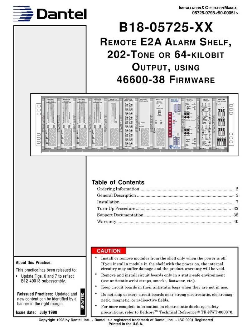
Dantel
Dantel A18-05775 Series User manual
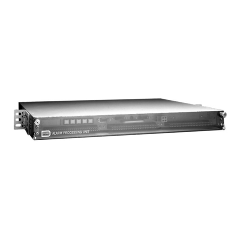
Dantel
Dantel 46131 User manual
Dantel
Dantel 46022-20 User manual
Dantel
Dantel 46022-30 User manual

Dantel
Dantel 05202 User manual
Dantel
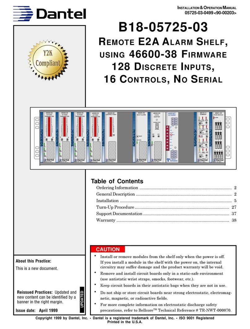
Dantel B18-05725-03 User manual
