r’s
Thank you for purchasing the model 701940 10 MHz Passive Probe. To ensure correct use, please
read this manual thoroughly before beginning operation. After reading the manual, keep it in a
convenient location for quick reference whenever a question arises during operation.
Contact information of Yokogawa offices worldwide is provided on the following sheet.
• PIM113-01Z2 Listofworldwidecontacts
Model 701940
10 MHz Passive Probe
Switchable attenuation ratio of 10:1 and 1:1
7thEdition:March2018(YMI)
AllRightsReserved,Copyright©2002,YokogawaElectricCorporation
AllRightsReserved,Copyright©2014,YokogawaTest&MeasurementCorporation
Printed in Japan
Notes
• Thecontentsofthismanualaresubjecttochangewithoutpriornoticeasaresultofcontinuing
improvements to the software’s performance and functions. The figures given in this manual may
differ from those that actually appear on your screen.
• Thecontentsofthismanualaresubjecttochangewithoutpriornoticeasaresultofcontinuing
improvements to the software’s performance and functions. The figures given in this manual may
differ from those that actually appear on your screen.
• Copyingorreproducingalloranypartofthecontentsofthismanualwithoutthepermissionof
YOKOGAWA is strictly prohibited.
The following symbols are used in this manual.
Improper handling or use can lead to injury to the user or damage to the instrument.
This symbol appears on the instrument to indicate that the user must refer to the
user’s manual for special instructions. The same symbol appears in the corresponding
placeintheuser’smanualtoidentifythoseinstructions.Inthemanual,thesymbolis
usedinconjunctionwiththeword“WARNING”or“CAUTION.”
WARNING Callsattentiontoactionsorconditionsthatcouldcauseseriousorfatalinjurytothe
user, and precautions that can be taken to prevent such occurrences.
CAUTION Callsattentionstoactionsorconditionsthatcouldcauselightinjurytotheuseror
damage to the instrument or the user’s data, and precautions that can be taken to
prevent such occurrences.
Note Calls attention to information that is important for proper operation of the instrument.
Safety Precautions
This product is designed to be used by a person with specialized knowledge.
Make sure to comply with the safety precautions mentioned hereafter when handling the probe.
YOKOGAWA assumes no responsibility for any consequences resulting from failure to comply with
thesesafetyprecautions.Also,readtheUser’sManualofthemeasuringinstrumentthoroughlysothat
you are fully aware of its specifications and handling, before starting to use the probe.
This manual is part of the product and contains important information. Store this manualin a safe place
close to the instrument so that you can refer to it immediately. Keep this manual until you dispose of
the instrument.
The following symbols are used on this instrument.
Handle with care. Refer to the user’s manual or service manual. This symbol appears on
dangerous locations on the instrument which require special instructions for proper handling
or use. The same symbol appears in the corresponding place in the manual to identify those
instructions.
Make sure to comply with the following safety precautions in order to prevent accidents
such as an electric shock which impose serious health risks to the user and damage to the
instrument.
WARNING
Grounding of the measuring instrument
Make sure to connect the protective grounding of the measuring instrument.
Ground lead of the probe
Make sure to connect the ground lead of the probe to the grounding potential.
Connecting the object of measurement
Makesuretoavoidanelectricshockwhenconnectingtheprobetotheobjectof
measurement.Donotremovetheprobefromthemeasuringinstrumentaftertheobjectof
measurement is connected.
Handling of the passive probe
Do not touch the probe’s input terminal or the probe itself with wet hands.
Make sure not to exceed the oscilloscope’s maximum input voltage in the following
cases:
• Whentheprobeattenuationratiois1:1
• Whentheoscilloscope’sinputcouplingisAC
DC voltage of the same electric potential as the probe’s input is applied to the
oscilloscope’s input.
Do not operate with suspected failures
Ifyoususpectthatthereisdamagetothisprobe,contactyournearestYOKOGAWAdealer
or sales representative.
Do not operate in wet/damp conditions
To avoid electric shock, do not operate this probe in wet or damp conditions.
Do not operate in explosive atmosphere
Toavoidinjuryorfirehazard,donotoperatethisprobeinanexplosiveatmosphere.
Do not disassemble or modify
Do not disassemble or modify the product. YOKOGAWA assumes no liability if you
disassemble or modify the product.
Avoid exposed circuitry
Toavoidinjury,removejewelrysuchasrings,watches,andothermetallicobjects.Donot
touchexposedconnectionsandcomponentswhenpowerispresent.
Damaged Signal Cable
Ifthesignalcableistornandtheinnermetalisexposedorifacolordifferentfromtheouter
sheath appears, stop using the cable immediately.
CAUTION
Maximum input voltage
Donotsupplyanyvoltagesexceedingthemaximuminputvoltagetotheprobe.
French
AVERTISSEMENT
Mise à la terre de l’instrument de mesure
S’assurer de connecter la mise à la terre protectrice de l’instrument de mesure.
Fil de terre de la sonde
S’assurer de connecter le fil de terre de la sonde au potentiel de mise à la terre.
Connexion de l’objet de la mesure
S’assurerd’éviterunchocélectriquelorsdelaconnexiondelasondeàl’objetdelamesure.
Nepasretirerlasondedel’instrumentdemesureaprèsavoirconnectél’objetdelamesure.
Manipulation de la sonde passive
Nepastoucherleterminald’entréedelasondeoulasondeelle-mêmeavecdesmains
mouillées.
S’assurer de ne pas dépasser la tension d’entrée maximum de l’oscilloscope dans les
cas suivants
• Lorsqueleratiod’atténuationdelasondeest1:1
• Lorsquelecouplaged’entréedel’oscilloscopeestenCA.
LatensionenCCdumêmepotentielélectriquequel’entréedelasondeestappliquéeà
l’entrée de l’oscilloscope.
Ne pas utiliser en cas de défaillances suspectées
Si vous suspectez que la sonde est endommagée, contactez votre revendeur ou
représentant commercial YOKOGAWA.
Ne pas utiliser dans des conditions humides
Afind’éviterunchocélectrique,nepasutilisercettesondedansdesconditionshumides.”
Ne pas utiliser dans une atmosphère explosive
Afin d’éviter des risques de blessures ou d’incendie, ne pas utiliser cette sonde dans une
atmosphèreexplosive.
Ne pas démonter ou modifier
Nepasdémonteroumodifierleproduit.YOKOGAWAsedégagedetouteresponsabilitési
vous démontez ou modifiez le produit.
Éviter les circuits exposés
Afind’éviterdesblessures,retirerlesbijouxcommelesbagues,montresetautresobjets
métalliques.Nepastoucherlesconnexionsetlescomposantsexposésaprèsmisesous
tension.
Câble de signal endommagé
Silecâbledesignalestdéchiréetquelemétalintérieurestexposéousiunecouleur
différentedelagaineexterneestvisible,arrêterimmédiatementd’utilisercecâble.
ATTENTION
Tension d’entrée maximum
Nepasappliqueràlasondedetensiondépassantlatensiond’entréemaximum.
Waste Electrical and Electronic Equipment
Waste Electrical and Electronic Equipment (WEEE), Directive
(ThisdirectiveisvalidonlyintheEU.)
This product complies with the WEEE directive marking requirement. This marking
indicates that you must not discard this electrical/electronic product in domestic
household waste.
Product Category
With reference to the equipment types in the WEEE directive, this product is classified
asa“Monitoringandcontrolinstruments”product.
WhendisposingproductsintheEU,contactyourlocalYokogawaEuropeB.V.office.
Do not dispose in domestic household waste.
Authorized Representative in the EEA
YokogawaEuropeB.V.istheauthorizedrepresentativeofYokogawaTest&MeasurementCorporation
forthisproductintheEEA.TocontactYokogawaEuropeB.V.,seetheseparatelistofworldwide
contacts,PIM113-01Z2.
Description
The model 701940 is a 10 MHz passive probe with switchable attenuation ratio of 10:1 and 1:1.
Thisprobecanbeusedforoscilloscopeswithinputimpedancesof1MΩ.
Appearance
This probe is composed of the probe and its accessories. Optional accessories are available to meet
various applications.
Orange
White
Green
Blue 1
10:1 - 1:1 Switch
5
2
3
4
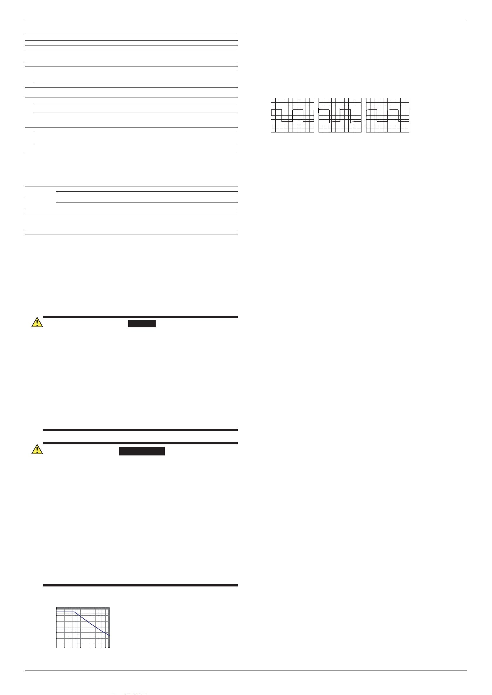
Trimmer
adjustment
screw 6
7
1
2
3
4
5
Ground lead
Pinchers tip
IC test tip
Ground attachment
Marker tip
B9852CW
B9852CX
B9852CY
B9852CZ
B9852DH
Name Part No.
Standard Accessories
Name Part No.
6
7
Mini clip converter
BNC adapter
B9852CR
B9852CS
Optional Accessories
(Sold Separately)
IM701940-01E1/2
IM701940-01E
7th Edition