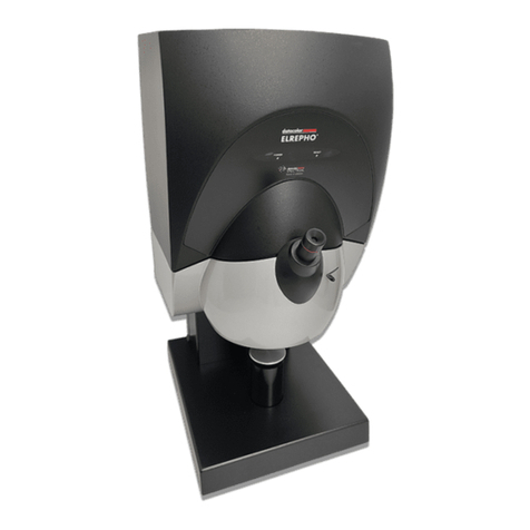
Datacolor ELREPHO User manual

Datacolor
Datacolor ELREPHO
User’s Guide

Datacolor ELREPHO User’s Guide (August, 2005) Part No. 4230-0398M Rev 1
All efforts have een made to ensure the accuracy of the information presented in this format.
However, should any errors e detected, Datacolor appreciates your efforts to notify us of
these oversights.
Changes are periodically made to this information and are incorporated into forthcoming versions.
Datacolor reserves the right to make improvements and/or changes in the product(s) and/or program(s)
descri ed in this material at any time.
Copyright © 2005 Datacolor. ALL RIGHTS RESERVED. This material may not e reproduced or
duplicated, in whole or in part, without the express written permission of Datacolor.
Microsoft®, MS-DOS®, and Microsoft Windows® are registered trademarks of Microsoft Corporation.
All other registered trademarks are the property of their respective owners.
Support Questions?
If you need help with a Datacolor product, please contact one of our top-rated technical support teams
located around the world for your convenience. You can find contact information elow for the
Datacolor office in your area.
Americas
+1.609.895.7465
+1.800.982.6496 (toll-free)
+1.609.895.7404 (fax)
Europe
+41.44.835.3740
+41.44.835.3749 (fax)
Asia Pacific
+852.2420.8606
+852.2420.8320 (fax)
Or Contact our Local Representative
Datacolor has representatives in over 60 countries. For a complete list, visit
www.datacolor.com/locations.
Manufactured by Datacolor
288 Shengpu Road, Suzhou Industrial Park, Suzhou, China
+86 512 625 80338

ELREPHO User's Guide Contents • i
Contents
Datacolor ELREPHO ......................................................................................... 1
A out the Datacolor ELREPHO ....................................................................................1
Feature Summary .........................................................................................................2
Accessories ..................................................................................................................2
Calibration Tiles ....................................................................................................2
Aperture Plates .....................................................................................................3
Ultra-Violet (UV) Filters.................................................................................................3
Electrical/Environmental Requirements ........................................................................3
Cable Installation .............................................................................................. 5
Overview ......................................................................................................................5
Power Ca le Installation ...............................................................................................5
Serial Ca le Installation ................................................................................................6
USB Ca le Installation..................................................................................................6
Cable Installation ...................................................................................................7
Driver Installation...................................................................................................7
Viewing/Changing Syste Port Assign ent .........................................................9
Changing the COM Port Assign ent in Datacolor Progra s .............................. 13
Installing Calibration Data ................................................................................... 13
Controls and Indicators .................................................................................. 15
Identification of Controls/Indicators ............................................................................ 15
Status Panel ............................................................................................................... 15
Powering Up ............................................................................................................... 16
Instrument Calibration ................................................................................... 17
Overview .................................................................................................................... 17
Installing Calibration Data ................................................................................... 17
Reflectance Cali ration .............................................................................................. 18
Reflectance Calibration Procedure ...................................................................... 19
UV Filter Calibration ............................................................................................ 19
Sample Presentation/Measurement ............................................................... 21
A out Sample Presentation/Management .................................................................. 21
Sample Presentation .................................................................................................. 22
Sample Viewing Port .................................................................................................. 22
Changing Aperture Plates .......................................................................................... 23
Tile Maintenance............................................................................................. 25
A out Tile Maintenance .............................................................................................. 25
Handling Tiles ............................................................................................................. 25
Cleaning Tiles ............................................................................................................. 25
Tile Storage ................................................................................................................ 26
Cleaning the Black Trap ............................................................................................. 26
Appendix ......................................................................................................... 27
Optical Block Diagram ................................................................................................ 27
Datacolor Elrepho Optical Block Diagram .................... Error! Bookmark not defined.
Instrument Specifications ........................................................................................... 28
Miscellaneous Technical Information ......................................................................... 29
RS-232C Connector Pin Assign ents ................................................................ 29
Compliance Statements ............................................................................................. 29
FCC Co pliance State ent ................................................................................ 29
Canadian Co pliance State ent ........................................................................ 29
Index ............................................................................................................... 31
ELREPHO User's Guide Datacolor ELREPHO • 1
Datacolor ELREPHO
About the Datacolor ELREPHO
The Datacolor ELREPHO is a color-measuring instrument designed specifically for use y the paper
industry. It incorporates the state-of-the-art CMOS integrated circuit technology used in other Datacolor
instruments, and employs a vertical mount design. It is intended for use as a device for measuring,
specifying and evaluating color in oth la oratory and production settings.
Below is a summary of the standard and optional features included with the Datacolor ELREPHO.
Standard features include the following:
• Pulsed xenon light source
• Multiple aperture sizes to accommodate samples of different sizes
• Automated zoom lens
• Automated, adjusta le ultra-violet filter used to control the UV component in the light source
• Automated UV cut-off filters for three wavelengths
Please refer to Appendix, Instru ent Specifications for co plete instru ent specifications.

2 • Datacolor ELREPHO ELREPHO User's Guide
Feature Summary
The Datacolor ELREPHO employs state-of-the-art features including the spectrometer, integrating
sphere, light source, and optics. Below is a summary of those features:
FEATURE DESCRIPTION PURPOSE/BENEFIT
Integrating sphere Barium coated sphere.
Industry standard.
Measurement
Geometry
Diffuse illumination, 0º
viewing
Conforms to the instrument specification
found in ISO 2469 standard.
SP2000 Spectral
Analyzer
Proprietary dual-
channel holographic
grating. 256-
photodiode linear
arrays used for oth
the reference and
sample channels.
Dual channel design provides continuous
monitoring of sample illumination and
compensates for changes. 256-photodiode
array enhances the precision of the
measurement.
Light source Pulsed xenon flash
lamp
Filtered to provide D65 illumination
including UV component.
Effective Bandwidth 10nm Reporting interval is 10nm. Maintains
consistency with reporting interval.
Accessories
The Datacolor ELREPHO comes with the following standard accessories:
Cables Calibration Accessories
• Six foot power ca le
• Serial ca le with connectors on either end
• USB ca le
• Black trap
• White tile
• Green tile
Calibration Tiles
A lack trap, white tile and green tile are provided with the instrument:
• The lack trap and white tile are used each time the instrument is cali rated.
• The green tile is used to perform an optional diagnostic test during instrument cali ration

ELREPHO User's Guide Datacolor ELREPHO • 3
Aperture Plates
Three aperture plates, with openings of different sizes, are included as standard accessories. The
identification is engraved on each plate.
Aperture Plates Designations
• Extra-Large Area View (XLAV)
• Small Area View (SAV)
• Ultra Small Area View (USAV)
Below are aperture plate specifications:
Aperture
Identification
Sample Area
Measured
Sample Area
Illuminated
XLAV 30mm 34.0 mm
SAV 5mm 9.0 mm
USAV 2.5mm 6.5 mm
NOTE
The area illuminated is always 4mm greater than the diameter measured, to reduce
translucency errors.
Tips for Aperture Selection
• Always use the largest possi le aperture size.
• Small (SAV) and ultra-small (USAV) plates should only e used for measurements of samples
that do not completely cover the opening of the larger aperture plates.
Ultra-Violet (UV) Filters
The Datacolor ELREPHO is fitted with an adjusta le UV filter to control the amount of ultra-violet light
present in the light source, and with UV cutoff filters used to cutoff specific wavelengths. Refer to the
Datacolor TOOLS User’s Guide Instrument Menu, UV Calibration and Advanced Options, UV
Calibration and Whiteness for detailed instructions on the cali ration and use of these filters.
Electrical/Environmental Requirements
Power 85 to 264 VAC, 47 to 63 Hz, 80 VA peak, 35 VA typical
Absolute Operating Environment 5º to 40º C, 20-85% RH, non-condensing
Interfaces Serial: RS232 9600/19200 aud
USB: 1.1

4 • Datacolor ELREPHO ELREPHO User's Guide
N O T E S

ELREPHO User's Guide Ca le Installation • 5
Cable Installation
Overview
WARNING
Read “Electrical and Environ ental Require ents” section before connecting your Datacolor
instru ent.
The Datacolor ELREPHO requires the use of two ca les, a power ca le and a communications ca le
(either serial or USB ca le) to connect the instrument to the computer.
The connections for these ca les are found on the ack of the instrument.
Power Cable Installation
Power is supplied to the ack of the unit via a 3-prong male connector. A six-foot power ca le is
provided with the instrument.
To connect the ca le:
1. Plug the female end of the power cord into the power receptacle on the rear panel of the
instrument.
2. Insert the plug into a standard AC outlet.
Serial cable
Power cable
USB cable

6 • Ca le Installation ELREPHO User's Guide
Serial Cable Installation
The serial ca le is shown elow:
1. Connect the 9-pin male connector on the serial ca le to the RS-232C female connector on the
rear panel of the instrument.
2. Connect the female connector on the serial ca le to a serial communications port on the ack
of the computer.
3. If there is more than one serial port on the computer, make a note of the port eing used. You
may need to enter this information into the program.
4. Tighten each connection securely to ensure proper signal.
See the Appendix for a description of the RS-232C connector pin assign ents.
USB Cable Installation
Instruments manufactured y Datacolor can now e connected to a USB port on a desktop system.
See Appendix, Syste Require ents for USB Cable Installation efore you attempt to connect to a
USB port.
Before ou Begin
• Close all programs currently running on the system.
• You will need the accessories listed elow to complete the installation:
− USB cable (provided y Datacolor)
− Datacolor CD ROM disk la eled USB Drivers and Docu entation (Datacolor Part
#2052-0330).
− Calibration diskette or CD included with the instrument (this is required only when
installing new instruments)

ELREPHO User's Guide Ca le Installation • 7
Three steps must e completed to ena le the USB port for use with the instrument:
• Install the USB Driver.
• Identify the system assignment for the USB port. This is accessed through the Control Panel
included with the Windows operating system.
• Change the com port assignment in the Datacolor applications software.
Cable Installation
The USB ca le provided with the system is shown elow:
One end of the ca le connects to a USB port on the instrument. The other connects to a USB port on
the computer. Connect the USB ca le to the instrument and to the USB port on the ack of the
computer.
In order to activate the USB ca le connection, you must also install a USB (software) driver.
river Installation
To prepare your computer and the Datacolor programs to communicate with your instrument using a
USB port, you must install software files onto the computer. When the instrument is connected to the
computer using a USB ca le, a Wizard displays on your computer screen.
1. Place the USB Drivers and Documentation CD into the CD-Rom drive.
2. Connect the USB ca le to oth the instrument and the computer. The window elow displays
automatically:
The New Hardware Wizard window will follow immediately:
To Instrument
To Computer

8 • Ca le Installation ELREPHO User's Guide
3. Click the Next utton at the ottom of the window. The wizard steps you through the
installation of the USB software files. For most installations, you can accept the defaults
selected y the Wizard.
4. Continue to click the Next utton at the ottom of each window in the Wizard. The program will
notify you when the procedure is completed.
CAUTION
o not remove the USB river C from the drive. The Wizard will close and then
immediately reopen. You will have to repeat the procedure a second time to successfully copy
the file.

ELREPHO User's Guide Ca le Installation • 9
5. When the “Welcome” screen appears again, click the Next utton.
6. Repeat the steps a ove a second time.
7. When you reach the final wizard screen, click Finish. At this time, the Wizard closes and the
installation is complete.
Viewing/Changing System Port Assignment
As part of the USB driver installation, a port num er is assigned to the USB port. The default selection
is the next availa le com port. Depending on the application you are running, you may need to know
this port assignment to configure the Datacolor applications program(s) to recognize the USB port.
NOTES
Some Datacolor programs automatically configure the USB port assignment. Others require
that you manually assign the port num er. Refer to the program User’s Guide for information
to assign/edit the instrument port num er.
If the computer has more than one USB port, the program will default to the first one availa le.
If you want to connect the instrument to a different USB port, you must assign the port
manually in the applications software.
The com port assignment is accessed through the Windows Control Panel as follows:
1. Click the Start utton at the ottom left of the screen.
The Start menu displays.
2. Place the cursor on Settings so that the program su menu displays, and click Control Panel.

10 • Ca le Installation ELREPHO User's Guide
3. When the Control Panel window displays, dou le-click on System.
The Systems Properties dialog ox displays.

ELREPHO User's Guide Ca le Installation • 11
4. Click the Hardware Tab. The dialog ox elow displays:
5. Click the Device Manager utton. The Device Manager window displays.
6. Go to the Ports heading. Click on the plus (+) to display the port selections.

12 • Ca le Installation ELREPHO User's Guide
7. Click USB Serial Port. The USB Serial Port (COM3) Properties dialog ox displays.
8. Click Port Settings. The dialog ox elow displays:
9. Click the Advanced utton. The Advanced Settings for COM3 dialog ox displays.

ELREPHO User's Guide Ca le Installation • 13
The field la eled COM Port Nu ber displays the current assignment for the USB port. To
change the port setting, click the drop-down list arrow. The list of COM ports is displayed.
10. Click on the port assignment to e used for the USB port.
11. When you have completed the changes, click OK.
Changing the COM Port Assignment in atacolor Programs
To ena le the USB port for color measurements, you may need to change the com port assignment in
the applications program. Refer to the progra docu entation for the specific Datacolor applications
progra you are running, for instructions to configure the instru ent.
Installing Calibration ata
For new instruments, you will need to install the white tile cali ration data. See also Instrument
Calibration in this guide for instructions to install the data.

14 • Ca le Installation ELREPHO User's Guide
N O T E S

ELREPHO User's Guide Controls and Indicators • 15
Controls and Indicators
Identification of Controls/Indicators
Status Panel
Below is the status panel for the Datacolor ELREPHO:
OPTION DESCRIPTION
Power Unit is connected to power supply, and power switch is on.
Ready Instrument is ready for use.
Sample viewer
Sample holder
Status panel
Power switch (not visible)
Lever to open sample viewer
Aperture plate (not visible)

16 • Controls and Indicators ELREPHO User's Guide
Powering Up
Use this simple procedure to start using your Datacolor ELREPHO.
1. Verify all ca le connections. The AC power cord should e plugged into an outlet. The serial
ca le should e attached to the instrument and host computer.
2. Turn on the host computer.
3. Turn on the power switch. This is located on the center right side, at the ack of the
instrument.
When power is applied, all mechanisms are automatically reset. The lights on the status panel
will flash for several seconds. When the Ready light remains on, your instrument is ready to
use.
NOTE
If the instrument power is not turned on efore a Datacolor program is launched, you
may receive an error message.
4. Launch a Datacolor program.
5. Prepare to cali rate the instrument. You will need the lack trap and the white cali ration tile.
NOTES
We recommend that you cali rate the instrument every 8 hours. Please refer to your
software docu entation for specific calibration instructions.
Your program may e configured to include an additional diagnostic test as part of the
cali ration procedure. The green tile is used to for this test. Refer to the progra
User’s Guide for instructions to co plete this test.
Top of Instrument
Power Switch
Table of contents
Other Datacolor Measuring Instrument manuals

Datacolor
Datacolor 650 User manual

Datacolor
Datacolor ColorReaderPRO DC10-1 User manual

Datacolor
Datacolor 45 Programming manual

Datacolor
Datacolor ColorReader DC10-2 User manual

Datacolor
Datacolor Elrepho 3000 User manual

Datacolor
Datacolor 200 User manual

Datacolor
Datacolor 200 User manual

Datacolor
Datacolor CHECK II User manual

Datacolor
Datacolor 45 User manual

Datacolor
Datacolor SpyderPRINT User manual