Datakom DK-40 User manual

DK-40 USER MANUAL V2.6 (02.08.2011)
K13D01-E - 1 -
http://www.datakom.com.tr
Tel: +90 216 466 84 60
Fax: +90 216 364 65 65
DK-40 COMPRESSOR CONTROLLER
INTRODUCTION
DK-40 is a state of the art unit for the control
of both screw and piston type compressors.
The unit integrates all functions needed in a
compressor system. Thus no extra units are
required in a compressor panel providing
cost reduction and simplicity.
The unit is directly powered from 230/400 volt
mains. It provides power supply for fault
switches and sensors. Thus external
transformer is not required in the panel.
The unit monitors mains phase voltages and
frequency. It features high/low voltage and
phase order protections.
The standard logic level serial port features
MODBUS communication. The unit allows
monitoring and programming through
computer.
FEATURES
Pressure driven automatic start and stop
Voltage Protection Relay function
Phase Order Protection Relay function
Mains phase voltages display
No need for external transformer
Star / Delta startup
Load solenoid control
1 programmable relay output
Optically isolated configurable digital inputs
2 pressure sensor inputs
2 temperature sensor inputs
Additional motor PTC input
Logic level serial port
MODBUS-RTU communication
Password protected front panel programming
Low panel depth, easy installation
Wide operating temperature range
Sealed front panel (IP54)
2 part connector system for easy installation

DK-40 USER MANUAL V2.6 (02.08.2011)
K13D01-E - 2 -
SAFETY NOTICE
Failure to follow below instructions will
result in death or serious injury
•
Electrical equipment should be installed only by qualified
specialist. No responsibility is assured by the
manufacturer or any of its subsidiaries for any
consequences resulting from the non-compliance to
these instructions.
•
Check the unit for cracks and damages due to
transportation. Do not install damaged equipment.
•Do not open the unit. There is no serviceable parts inside.
•
Fuses must be connected to the power supply and phase
voltage inputs, in close proximity of the unit.
•
Fuses must be of fast type (FF) with a maximum rating of
6A.
•
Disconnect all power before working on equipment.
•
When the unit is connected to the network do not touch
terminals.
•
Any electrical parameter applied to the device must be in
the range specified in the user manual.
•
Do not try to clean the device with solvent or the like.
Only clean with a dry cloth.
•
Verify correct terminal connections before applying
power.
•
Only for front panel mounting.

DK-40 USER MANUAL V2.6 (02.08.2011)
K13D01-E - 3 -
TABLE OF CONTENTS
Section
1. INSTALLATION
1.1. FRONT / REAR PANELS
1.2. MECHANICAL INSTALLATION
1.3. ELECTRICAL INSTALLATION
1.4. CONNECTION DIAGRAM
2. PUSHBUTTON FUNCTIONS
3. DISPLAY NAVIGATION
4. MODES OF OPERATION
5. ALARMS AND WARNINGS
6. OTHER FEATURES
6.1. RESETTING SERVICE COUNTERS
6.2. MODIFYING HOUR COUNTERS
6.3. SELECTION OF HOUR COUNTING METHOD
6.4. CONNECTION TOPOLOGIES
6.5. PREVENTING PRESSURE LOSS
6.6. ALARM HISTORY
7. INPUTS
8. RELAY OUTPUTS
9. PROGRAMMING
9.1. INTRODUCTION TO PROGRAMMING
9.2. PARAMETER LIST
10. MODBUS COMMUNICATIONS
10.1. DESCRIPTION
10.2. MODBUS REGISTER LIST
11. MULTIPLE CONTROLLER OPERATION
12. DECLARATION OF CONFORMITY
13. TECHNICAL SPECIFICATIONS

DK-40 USER MANUAL V2.6 (02.08.2011)
K13D01-E - 4 -
1. INSTALLATION
Before installation:
•Read the user manual carefully, determine the correct connection diagram.
•Remove all connectors and mounting brackets from the unit, then pass the unit through
the mounting opening.
•Put mounting brackets and tighten. Do not tighten too much, this can brake the enclosure.
•Make electrical connections with plugs removed from sockets, then place plugs to their
sockets.
•Note that the power supply terminal is separated from measurement terminals.
Below conditions may damage the device:
•Incorrect connections.
•Incorrect power supply voltage.
•Voltage at measuring terminals beyond specified range.
•Connecting or removing data terminals when the unit is powered-up.
•Overload or short circuit at relay outputs
•Voltage applied to digital inputs over specified range.
•High voltage applied to communication port.
Below conditions may cause abnormal operation:
•Power supply voltage below minimum acceptable level.
•Power supply frequency out of specified limits

DK-40 USER MANUAL V2.6 (02.08.2011)
K13D01-E - 5 -
1.1 FRONT / REAR PANELS
1.2 MECHANICAL INSTALLATION
Panel Cutout Required Panel Depth

DK-40 USER MANUAL V2.6 (02.08.2011)
K13D01-E - 6 -
1.3 ELECTRICAL INSTALLATION
Do not install the unit close to high electromagnetic noise
emitting devices like contactors, high current busbars,
switchmode power supplies and the like.
Although the unit is protected against electromagnetic disturbance, excessive disturbance
can affect the operation, measurement precision and data communication quality.
•ALWAYS remove plug connectors when inserting wires with a screwdriver.
•Fuses must be connected to the power supply and phase voltage inputs, in close
proximity of the unit.
•Fuses must be of fast type (FF) with a maximum rating of 6A.
•Use cables of appropriate temperature range.
•Use adequate cable section, at least 0.75mm
2
(AWG18).
•Follow national rules for electrical installation.
•Use only the appropriate cable and connector for serial port connection.

DK-40 USER MANUAL V2.6 (02.08.2011)
K13D01-E - 7 -
1.4 CONNECTION DIAGRAM

DK-40 USER MANUAL V2.6 (02.08.2011)
K13D01-E - 8 -
2. PUSHBUTTON FUNCTIONS
Programming and measurement displays are visualized using below buttons:
BUTTON DESCRIPTION
FUNCTION
MENU
Displays next parameter.
Resets faults.
Saves adjusted value.
RUN
Run the compressor and reset existing
alarms.
Increase value.
STOP
Stop the compressor and reset existing
alarms.
Decrease value.

DK-40 USER MANUAL V2.6 (02.08.2011)
K13D01-E - 9 -
3. DISPLAY NAVIGATION
Usually the upper display shows the pressure-1 value or the pressure switch-1 position.
The lower display shows the temperature-1.
Other values are scrolled by pressing the MENU
button. For better clarity, the upper
display will show the parameter name and the lower display will show the parameter value.
Some parameters are longer than 1 display. For these parameters, when MENU
button
is presssed the parameter name apeears on the upper display. When MENU button is
released, the parameter value is shown on both displays.
Display of some parameters are selectable with program parameters and
may differ following compressor manufacturers.
In the occurrence of a fault condition, the fault code will appear on the
upper display.
Below is a list of messages shown on the upper display in normal operation,
programming and alarm display modes:
MESSA
GE DESCRIPTION MODE
bar
barbar
bar
set
setset
set
Start pressure and stop pressure set
values Display
FrQ
FrQFrQ
FrQ
Mains frequency Display
L12
L12L12
L12
L1-L2 phase-to-phase voltage Display
L23
L23L23
L23
L2-L3 phase-to-phase voltage Display
L31
L31L31
L31
L3-L1 phase-to-phase voltage Display
SH
SHSH
SHA
AA
A
Hours remaining to service A Display / Program / Alarm
SHB
SHBSHB
SHB
Hours remaining to service B Display / Program / Alarm
SHC
SHCSHC
SHC
Hours remaining to service C Display / Program / Alarm
SHD
SHDSHD
SHD
Hours remaining to service D Display / Program / Alarm

DK-40 USER MANUAL V2.6 (02.08.2011)
K13D01-E - 10 -
MESSA
GE DESCRIPTION MODE
SHE
SHESHE
SHE
Hours remaining to service E Display / Program / Alarm
C-H
C-HC-H
C-H
Total compressor hours
(ON_LOAD+OFF_LOAD+STOP) Display
R-H
R-HR-H
R-H
Total Run Hours
(ON_LOAD+OFF_LOAD) Display
L-H
L-HL-H
L-H
Total load time (load contactor active) Display
o/o
o/oo/o
o/o
Load hours / Run hours percentage Display
E-t
E-tE-t
E-t
Motor PTC value or switch position Display
t-
t-t-
t-2
22
2
Temperature-2 value or switch position Display
d-p
d-pd-p
d-p
Differential Pressure Display
n--
n--n--
n--
Remaining starts for the last hour Display
rEL
rELrEL
rEL
Software version Display
Ah1
Ah1Ah1
Ah1
Alarm history 1 Display
n-C
n-Cn-C
n-C
Switch closed Display
N-O
N-ON-O
N-O
Switch open Display
SEP
SEPSEP
SEP
Waiting for separator filter pressure drop Display
S P
S PS P
S P
Remote Stop mode Display
RUN
RUNRUN
RUN
Remote Start mode Display
aL1
aL1aL1
aL1
Alarm code 01 Display
a99
a99a99
a99
Alarm code 99 Display
p99
p99p99
p99
Program parameter 99 Program
usr
usrusr
usr
Enter password Program
seL
seLseL
seL
Select parameter Program

DK-40 USER MANUAL V2.6 (02.08.2011)
K13D01-E - 11 -
4. MODES OF OPERATION
Selecting the operating mode:
At power-up, the unit will turn all lights on for 3 seconds in order to allow lamp check. Then
it goes in the STOP mode and the stop led turns on.
The compressor may be run through Remote Start signal (upper display shows
rUn
rUnrUn
rUn
for 5
seconds) or by pressing the RUN
button.
If P28 Safety Timer has not elapsed, the run led will flash until expiration of the timer. Then
if the pressure is below the limit set by P05 Start Pressure, then the compressor will run.
In the occurrence of an alarm the compressor stops
immediately and the upper display shows the alarm code.
A comprehensive list of alarm codes is given in chapter 5.
The compressor may be stopped with Remote Stop signal (upper display shows
StP
StPStP
StP
for 5
seconds) or the STOP button.
Stop procedure:
STOP led starts flashing.
If the compressor is loaded, then the LOAD relay will release and the compressor
continues to run during P28 Safety Timer or P26 Unload Timer (whichever is longer).
At this step, operation may be resumed by pressing the RUN
button. If STOP
button is pressed during unloaded operation, then the compressor stops immediately.
The stop led flashes until the compressor comes to complete stop.
When STOP
button is pressed, if the compressor is
running unloaded, then it will continue to run until
expiration of P26 Unload Timer.
The compressor may be immediately stopped by
pressing again the STOP
button.

DK-40 USER MANUAL V2.6 (02.08.2011)
K13D01-E - 12 -
Start procedure:
If mains phase voltages and frequency are between preset limits and the phase order is
correct, then the POWER led will turn on. The compressor may run only when the power
led is on. Otherwise it cannot run.
The Run mode of operation is selected by pressing the RUN button or by sending
REMOTE START/STOP signal (if enabled). At this position, when the pressure falls below
P05 Start Pressure (or pressure switch closes) the unit decides to run the compressor.
Befor running the compressor the STAR relay output becomes active. After P15 Delay
between Relays Timer LINE relay will be activated. Thus the motor starts in star mode.
After P23 Star Timer the STAR relay opens and after P24 Star/Delta Transition Timer the
DELTA relay operates.
After P25 Timer before Loading the LOAD relay operates and the compressor starts
producing compressed air.
Unloading and reloading:
When the pressure reaches P04 Stop Pressure (or pressure switch opens) then the LOAD
relay opens and the compressor runs unloaded during P26 Unload Timer. If the pressure
falls below P05 Start Pressure before the expiration of the timer, then the LOAD relay
energizes again.
Stopping and restarting:
If the pressure stays over the P05 Start Pressure limit (or pressure switch opened) during
P26 Unload Timer, then the DELTA relay will release. After P15 Delay between Relays
timer, the LINE relay releases.
In this situation, the RUN led starts flashing.
The maximum number of starts that the compressor may perform in one hour is adjusted
with P37 Maximum Starts per Hour parameter.
If the maximum start count is reached, then the compressor stopping is disabled and it will
continue to run unloaded until the end of 1 hour period.

DK-40 USER MANUAL V2.6 (02.08.2011)
K13D01-E - 13 -
5. ALARMS AND WARNINGS
Abnormal situations in the compressor are evaluated under 3 different categories as
ALARMS, WARNINGS and SERVICE REQUESTS.
Warnings are lowest level fault conditions and generate only visual warning, not affecting
the compressor operation.
Alarms are highest level fault conditions and cause the compressor to stop immediately,
the alarm relay to become active (if enabled by programming) and visual warning to occur.
If any fault condition occurs, the fault code will appear on the upper display and the related
fault category led turns on. (WARNING, ALARM or SERVICE)
Alarms and warnings may be reset by pressing the MENU button. The EMERGENCY
STOP alarm cannot be reset by pressing buttons, the alarm signal must be removed.
Service warnings may affect the compressor operation
depending on the amount exceeding the service period.
TIME REMAINING TO
SERVICE REACTION
> 100 hours No warning given.
100hours Service warning is given and SERVICE led turns on. The
compressor continues normal operation.
0 hour
The compressor stops. Service warning is given and
SERVICE led turns on. The compressor resumes normal
operation when RUN button is pressed.
-100 hours
The compressor stops. Service warning is given and
SERVICE led turns on. The compressor resumes normal
operation when RUN button is pressed.
-120 to -200 hours,
every 20 hours
The compressor stops. Service warning is given and
SERVICE led turns on. The compressor resumes normal
operation when RUN button is pressed.
-210 to -300 hours,
every 10 hours
The compressor stops. Service warning is given and
SERVICE led turns on. The compressor resumes normal
operation when RUN button is pressed.
-300 hours
The compressor stops. Service warning is given and
SERVICE led turns on. The compressor will not operate
again unless the service counter is reset.

DK-40 USER MANUAL V2.6 (02.08.2011)
K13D01-E - 14 -
FAULT CODES LIST
SYMBOL
CODE
DESCRIPTION TİP
AL1 01 Security Pressure Switch Opened ALARM
AL2 02 High Pressure ALARM
AL3 03 Pressure Sensor Fail ALARM
AL4 04 High Temperature ALARM
AL5 05 High Temperature WARNING
AL6 06 Temperature Sensor Fail ALARM
AL7 07 Low Temperature ALARM
AL8 08 Fan Motor High Temperature ALARM
AL9 09 Motor PTC High Temperature ALARM
A10 10 Voltage Unbalance ALARM
A11 11 High Voltage ALARM
A12 12 Low Voltage ALARM
A13 13 High Frequency ALARM
A14 14 Low Frequency ALARM
A15 15 Phase Squence Fail ALARM
A16 16 Air Filter Clogged WARNING
A17 17 Maximum starts per hour exceeded WARNING
A18 18 Emergency Stop ALARM
A19 19 Internal Warning WARNING
A20 20 Pressure Difference ALARM
A21 21 High Pressure-2 ALARM
A22 22 Pressure-2 Sensor Fail ALARM
A23 23 High Temperature-2 / Delta (tS2-tS1) ALARM
A24 24 Temperature-2 Sensor Fail ALARM
A25 25 Low Temperature-2 ALARM
A26 26 Air In Separator WARNING
A27 27 Delta Temperature-2 Warning WARNING
A28 28 Main Motor thermal ALARM
A29 29 Low Pressure-2 ALARM
SHA 100 Service A Period Elapsed SERVICE
SHb 101 Service B Period Elapsed SERVICE
SHC 102 Service C Period Elapsed SERVICE
SHD 103 Service D Period Elapsed SERVICE
SHE 104 Service E Period Elapsed SERVICE
Stp 200 Remote Stop -

DK-40 USER MANUAL V2.6 (02.08.2011)
K13D01-E - 15 -
6. OTHER FEATURES
6.1. RESETTING SERVICE COUNTERS
Service counters can only be reset when the compresssor
is in STOP mode.
In order to reset service counters:
- Hold MENU and RUN buttons pressed for 3 seconds. If the high level
password is not entered in the last 90 minutes, the unit will ask the password.
- Enter the password.
- The upper display will show
sH
sHsH
sHA
AA
A
hours remaining for SERVICE A message.
- Press again the MENU button. The hours remaining for SERVICE A will appear
flashing on the display.
- In order to reset the hours remaining for SERVICE A, hold pressed MENU button
for 3 seconds.
- The upper display will show the next service counter which is
SHB
SHBSHB
SHB
hours remaining for
SERVICE B message.
- Press again the MENU button. The hours remaining for SERVICE B will appear
flashing on the display.
- In order to reset the hours remaining for SERVICE B, hold pressed MENU button
for 3 seconds.
- By pressing the MENU button again, below counters can be scrolled and reset:
SHC
SHCSHC
SHC
: hours remaining for SERVICE C
SHD
SHDSHD
SHD
: hours remaining for SERVICE D
SHE
SHESHE
SHE
: hours remaining for SERVICE E
After the last counter, the display will return to pressure-
temperature display mode.

DK-40 USER MANUAL V2.6 (02.08.2011)
K13D01-E - 16 -
6.2. MODIFYING HOUR COUNTERS
The unit holds 3 different run hour counters:
MESSAGE
DESCRIPTION
C-H
C-HC-H
C-H
Total compressor hours (ON_LOAD+OFF_LOAD+STOP)
This counter increments while the RUN led is on.
R-H
R-HR-H
R-H
Total motor run hours
(ON_LOAD+OFF_LOAD)
This counter increments while the motor runs.
L-H
L-HL-H
L-H
Total load time (load contactor active)
This counter increments while LOAD led is on.
Hour counters can only be modified while the compresor
is in STOP mode.
In order to modify hour counters:
- Hold pressed together MENU , RUN and STOP buttons for 3 seconds. If
the high level password is not entered in the last 90 minutes, the unit will ask password
(USR
USRUSR
USR).
- Enter password.
- The upper display will show
C-H
C-HC-H
C-H
message.
- Adjust required hour counter value with RUN and STOP buttons.
- Press MENU button for 3 seconds, the display wil show SEt message and the
counter will be adjusted to the new value. If MENU button is pressed for short
duration, then the value will not be modified and the next hour counter will be displayed.
Same steps are repeated for further modification.
After modifications, the display will return to pressure-
temperature display mode.

DK-40 USER MANUAL V2.6 (02.08.2011)
K13D01-E - 17 -
6.3. SELECTION OF HOUR COUNTING METHOD
The unit offers the possibility of incrementing hour counters with a variable coefficient,
depending on air end temperature.
The use of variable coefficient is selected with P89 Variable Hour counting coefficient. If
this parameter is 0, all service and hour counters will increment with a fixed coefficient of
1.00.
If Variable Hour Counting is activated:
Running on load:
below 90 °C, coefficient = 1.00
between 90 and 95 °C, coefficient = 1.50
between 95 and 100 °C, coefficient = 2.00
above 100 °C, coefficient = 3.00
Running off load
below 90 °C, coefficient = 0.50
between 90 and 95 °C, coefficient = 0.75
between 95 and 100 °C, coefficient = 1.00
above 100 °C, coefficient = 1.50
These coefficients apply to both service and compressor
hour counters.

DK-40 USER MANUAL V2.6 (02.08.2011)
K13D01-E - 18 -
6.4. CONNECTION TOPOLOGIES
The unit supports various connection topologies. The topology is selected through
parameter P48.
Different topologies and terminal connections are as below:
P48 = 3
P48 = 1
P48 = 2
P48 = 3
The power supply and measuring terminals
of the unit are isolated. In order to enable
above topology, the unit must be specially
manufactured.

DK-40 USER MANUAL V2.6 (02.08.2011)
K13D01-E - 19 -
6.5. PREVENTING PRESSURE LOSS
If the pressure stays above the P05 Start Pressure, during P26 Unload Timer then
the unit will stop the motor. If the pressure falls below P05 Start Pressure then the motor
will run again.
Before the compressor is loaded, a timer equal to P23+P24+P25+P15x3 will be
elapsed.
During this period, depending on the air consumption, the pressure may fall below
P05 Start Pressure.
In most applications, it is required that the pressure never falls below the P05 Start
Pressure limit.
In order to prevent this unwanted situation, the unit offers 3 different operating
modes selected through program parameter P45. The unit calculates dynamically the
restart pressure (Pi)
P45 = 0 No special care taken. Pi = P05.
P45 = 1 When the compressor is loaded, if the pressure is below P05 Start Pressure,
then the Restart Pressure (Pi) is incremented by 0.1 bar.
When the compressor is loaded, if the pressure is above P05 Start Pressure, then the
Restart Pressure (Pi) is decremented by 0.1 bar. Thus the unit tries to load at exactly P05
Start Pressure.
P45 = 2
When the compressor reaches P04 Stop Pressure, the unit measures the air
consumption during 8 seconds, then calculates the Restart Pressure (Pi) again.
At the end of P26 Unload Timer, if the pressure is above
P05 Start Pressure and below Pi Restart Pressure, then the
motor will continue to run unloaded.

DK-40 USER MANUAL V2.6 (02.08.2011)
K13D01-E - 20 -
6.6. ALARM HISTORY
The unit keeps the list of 9 most recent alarm records.
A new occurring alarm will appear at the top of the list.
The alarm list may be visualized on the screen or read through Modbus.
The alarm list is kept in a non-volatile memory and is not affected by power failures.
The alarm will be added to the list only if it is different from the previous alarm or the
motor has run at least 6 minutes after its previous occurrence.
In order to visualize the latest alarm in the history press MENU button until
Ah
AhAh
Ah1
11
1
(alarm history 1) comes to the display.
To visualize previous alarms use RUN and STOP pushbuttons.
When the alarm history is scrolled the STOP
button
is always active and stops the compressor. However the
RUN
button is not active and does not run the
compressor. To scroll the alarm history when the
compressor is running please use only the RUN
button.
Table of contents
Other Datakom Controllers manuals
Datakom
Datakom DK-70 User manual
Datakom
Datakom DKG-225 User manual
Datakom
Datakom D-500 MK2 User manual
Datakom
Datakom DKG-119 User manual
Datakom
Datakom DKG-325 User manual
Datakom
Datakom DK-45 MK2 User manual
Datakom
Datakom D-100 MK2 User manual
Datakom
Datakom DKG-307 User manual
Datakom
Datakom DKG-109 User manual
Datakom
Datakom D-300 MK2 User manual
Datakom
Datakom DKG-209 User manual
Datakom
Datakom DKG-114 Manual
Datakom
Datakom D-500 MK3 User manual

Datakom
Datakom DKG-225 User manual
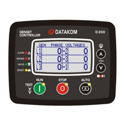
Datakom
Datakom D-200 MK2 User manual
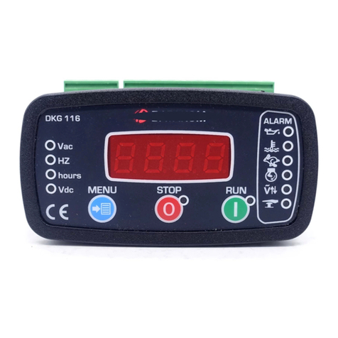
Datakom
Datakom DKG-116 User manual
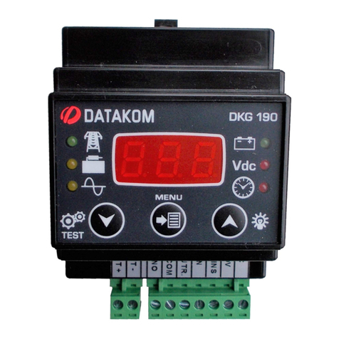
Datakom
Datakom DKG-190 User manual
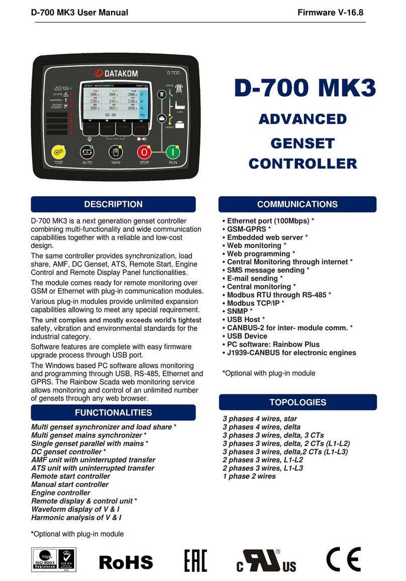
Datakom
Datakom D-700 MK3 User manual
Datakom
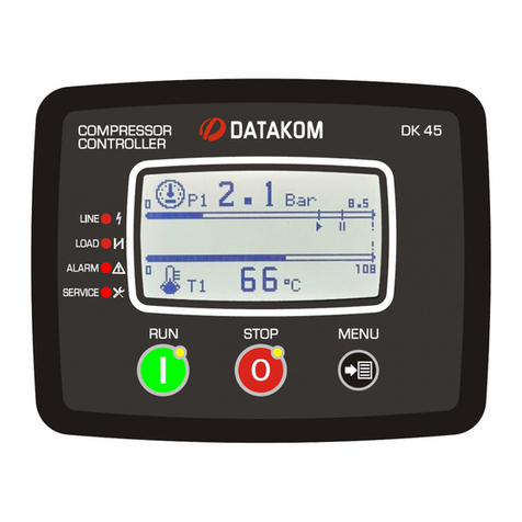
Datakom DK-45 User manual

Datakom
Datakom D-500 MK3 User manual
