manuals.online logo
Brands
  1. Home
  2. •
  3. Brands
  4. •
  5. Datakom
  6. •
  7. Controllers
  8. •
  9. Datakom DKG-114 Manual

Datakom DKG-114 Manual

114_TANE.doc
DKG-114 MANUAL AND REMOTE START UNIT
APPLICATIONS
-Manual gensets,
-Automatic gensets with voltage relay
-Diesel pumps
-Marine gensets
-Marine auxiliary gensets
-Marine diesel engines
DESCRIPTION
The DATAKOM model DKG-114 is a low
cost, microprocessor controlled generator
control unit designed to start and stop the
genset both manually and remotely. The
manual control is made using the pushbuttons
on the front panel. The remote control is made
via the remote start input signal.
In the STOP position, the DC supply is
removed from the module, thus zero power
consumption is achieved.
The unit powers up when the RUN button is
pressed or battery+ is applied to the REMOTE
START input. This will also energize the fuel
solenoid relay. The engine is automatically
started 3 times until operation.
Once the engine is running, the device
monitors the internal protections and external
fault inputs. Only the first occurring alarm will
be displayed, disabling further alarms.
If the STOP button is pressed or the
REMOTE START signal is removed, the engine
will be stopped.
The unit offers jumper selectable operating
parameters, which lets it to be used in a large
variety of applications. The jumper options
select the operating voltage of the unit, the
auxiliary relay function, the engine running
signal type and the cooldown cycle.
The unit fits into a standard 72x72mm
panel meter opening and offers a very cost
effective and space saving solution for the
basic genset control. Thanks to the completely
sealed structure, IP65 protection degree is
achieved from the front panel.
The unit works on both 12 Volt and 24 Volt
gensets.
FEATURES
Both manual and remote controlled engine
starting and stopping,
Automatic shutdown on fault condition,
Optional cooldown cycle on remote start
operation,
Optional energize to stop or preheat output,
Survives cranking dropouts,
High current relay outputs,
Selectable engine running signal (from genset
voltage or charge alternator),
Delayed overspeed and underspeed alarm,
Sealed front panel, IP65 protection.
Plug-in connection system for easy
replacement,
Low cost,
Small dimensions,
Standard panel dimensions, (72x72mm)
114_TANE.doc
INPUTS AND OUTPUTS
FUEL: Fuel solenoid control.(10 A @28V-DC)
START: Engine starter solenoid control. (10 A
@28V-DC)
AUXILIARY: Positive output relay activated by
any alarm condition (or optionally stop solenoid
or preheat output). (10 A @28V-DC)
LOW OIL PRESSURE SWITCH: negative closing
switch input for low oil pressure protection.
HIGH TEMP SWITCH: negative closing switch
input for engine high temperature protection.
DC SUPPLY: 12 or 24 volts DC, (+) and (-)
terminals.
REMOTE START/SPARE FAULT: If the battery
positive voltage is applied to this input the
genset will start. If the positive voltage is
removed, it will stop. A battery negative
connection will generate a SPARE ALARM.
CHARGE: This terminal will be connected to the
charge alternator D+ terminal. It will supply the
excitation current and monitor the charge
alternator status.
G: Generator phase voltage.
NEUTRAL: Generator neutral terminal.
TECHNICAL SPECIFICATIONS
Alternator voltage: 277V-AC (Ph-N)
Alternator frequency: 0-200Hz.
DC Supply Range: 9 to 33 V-DC.
4 to 33 V-DC while cranking
Current consumption:
0 ma-DC in OFF mode
250 mA-DC max. (Relay outputs open)
Total DC Current Output Rating: 10A-DC.
Max. Current for each Terminal: 10A-RMS.
Operating temp: -30°C (-22°F) to 70°C (158°F).
Storage temp: -40°C (-40°F) to 80°C (176°F).
Maximum humidity: 95% non-condensing.
IP Protection: IP65 from front panel, IP30 from
the rear.
Dimensions: 72 x 72 x 43mm (WxHxD)
Mounting: Front panel mounted with rear
retaining steel spring.
Panel cut-out dimensions: 68 x 68mm.
Weight: 180 g (approx.)
Charge excitation current: 36mA @ 12V-DC.
Cranking dropouts: survives 0V for 100ms.
Genset low frequency limit: 30Hz.
Genset high frequency limit: 57Hz.
Frequency error delay: 3 sec.
Preheat timer: 10 or 30 sec selectable.
Number of starts: 3
Start duration: 6 sec.
Wait between starts: 10 sec.
Cooldown duration: 2 min.
Stop duration: 30 sec.
Alarm duration: 1 minute.
Protection delay: 10 sec.
Case Material: Flame Retardant High
Temperature ABS (UL94-V0, 110°C)
Conformity (EU directives)
-73/23/EEC and 93/68/EEC
-89/336/EEC, 92/31/EEC and 93/68/EEC
Norms of reference:
EN 61010 (safety requirements)
EN 50081-2 (EMC requirements)
EN 50082-2 (EMC requirements)
DATAKOM Electronics Limited
Tel : +90-216-466 84 60
Fax : +90-216-364 65 65
e-mail : datakom@datakom.com.tr
http: www.datakom.com.tr

Other Datakom Controllers manuals

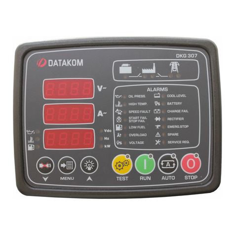
Datakom DKG-307 User manual

Datakom

Datakom DKG-307 User manual

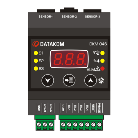
Datakom DKM-046 User manual

Datakom

Datakom DKM-046 User manual

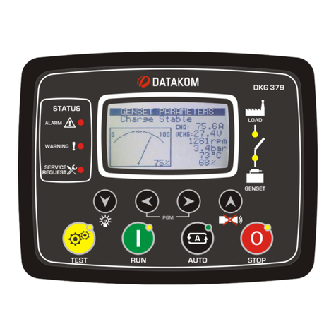
Datakom DKG-379 User manual

Datakom

Datakom DKG-379 User manual

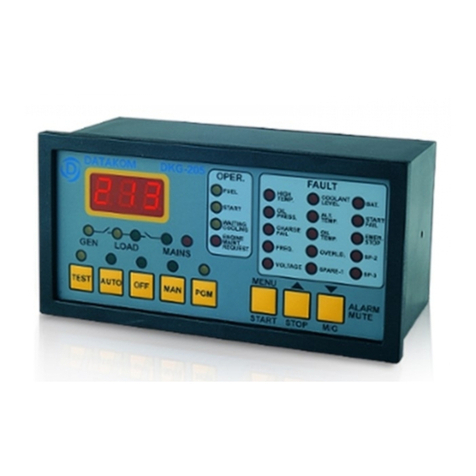
Datakom DKG-205 User manual

Datakom

Datakom DKG-205 User manual

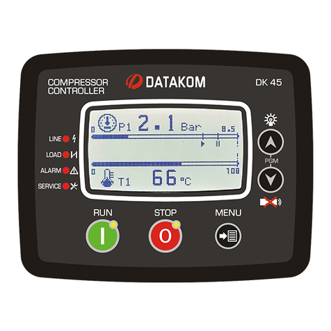
Datakom DK-45 MK2 User manual

Datakom

Datakom DK-45 MK2 User manual

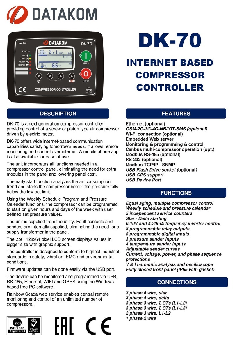
Datakom DK-70 User manual

Datakom

Datakom DK-70 User manual

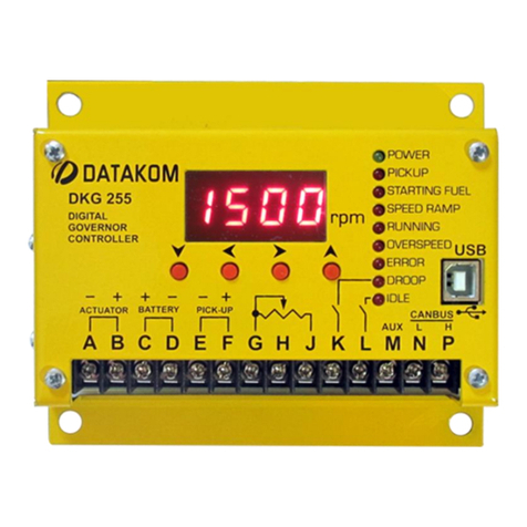
Datakom DKG-255 User manual

Datakom

Datakom DKG-255 User manual

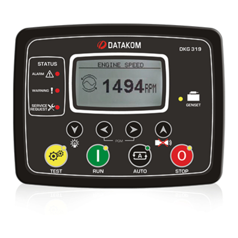
Datakom DKG-319 User manual

Datakom

Datakom DKG-319 User manual

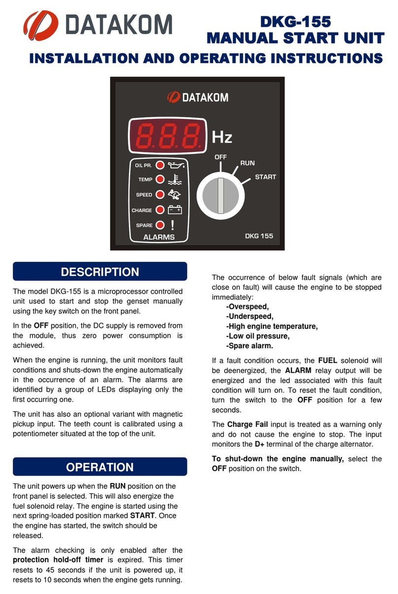
Datakom DKG-155 User manual

Datakom

Datakom DKG-155 User manual

Datakom DKG-116 User manual

Datakom

Datakom DKG-116 User manual

Datakom DKG-209 User manual

Datakom

Datakom DKG-209 User manual

Datakom DK-45 User manual

Datakom

Datakom DK-45 User manual

Datakom DKG-325 User manual

Datakom

Datakom DKG-325 User manual

Datakom D-500 MK2 User manual

Datakom

Datakom D-500 MK2 User manual

Datakom DKG-509 User manual

Datakom

Datakom DKG-509 User manual

Datakom DKG-108 User manual

Datakom

Datakom DKG-108 User manual

Datakom D-100 MK2 User manual

Datakom

Datakom D-100 MK2 User manual

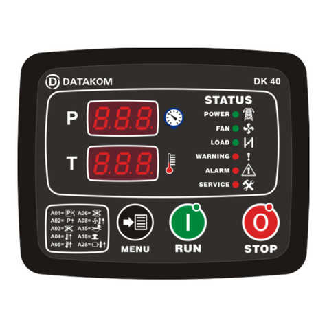
Datakom DK-40 User manual

Datakom

Datakom DK-40 User manual

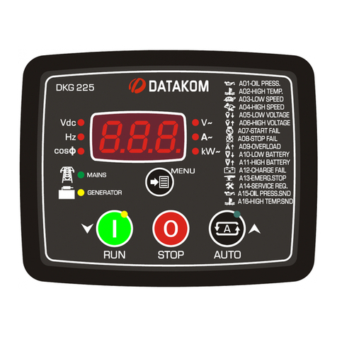
Datakom DKG-225 User manual

Datakom

Datakom DKG-225 User manual

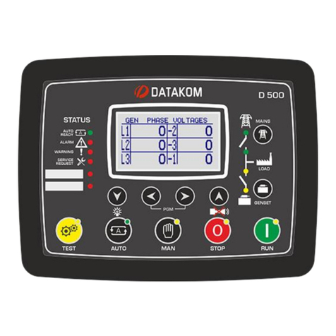
Datakom D-500 MK3 User manual

Datakom

Datakom D-500 MK3 User manual

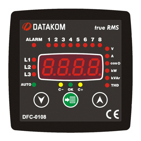
Datakom DFC-0108 User manual

Datakom

Datakom DFC-0108 User manual

Datakom DKG-225 User manual

Datakom

Datakom DKG-225 User manual

Datakom D-500 MK3 User manual

Datakom

Datakom D-500 MK3 User manual

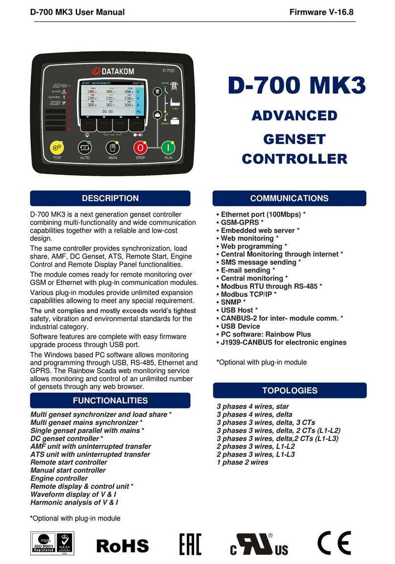
Datakom D-700 MK3 User manual

Datakom

Datakom D-700 MK3 User manual

Popular Controllers manuals by other brands

KMC Controls MCP-1020 Series installation guide

KMC Controls

KMC Controls MCP-1020 Series installation guide

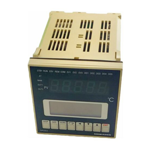
Shimaden SR253 Series instruction manual

Shimaden

Shimaden SR253 Series instruction manual

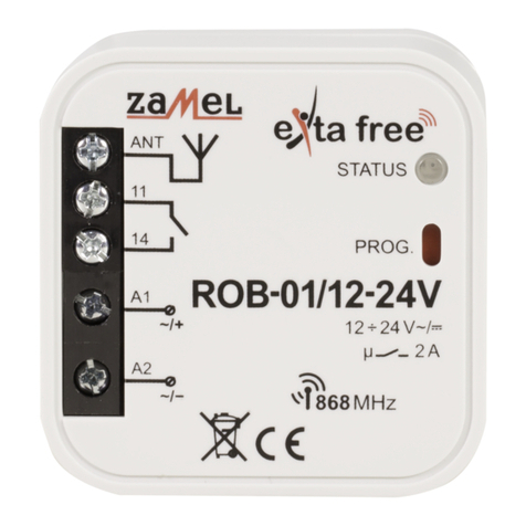
Zamel Extra Free ROB-01/12-24V manual

Zamel

Zamel Extra Free ROB-01/12-24V manual

DIGITIZE RAD-8LS Installation & operation manual

DIGITIZE

DIGITIZE RAD-8LS Installation & operation manual

LOXONE Touch Air quick guide

LOXONE

LOXONE Touch Air quick guide

Chauvet LED-CHVA user manual

Chauvet

Chauvet LED-CHVA user manual

Mindman MAER200 Series Service manual

Mindman

Mindman MAER200 Series Service manual

hopf 7406RC Technical manual

hopf

hopf 7406RC Technical manual

SOLARA SR135TL user manual

SOLARA

SOLARA SR135TL user manual

NI GPIB-SCSI-A Getting started

NI

NI GPIB-SCSI-A Getting started

iNels SA3-02M quick start guide

iNels

iNels SA3-02M quick start guide

Norac UC4+ installation manual

Norac

Norac UC4+ installation manual

Supermicro AOC-S25G-m2S user guide

Supermicro

Supermicro AOC-S25G-m2S user guide

Gossen MetraWatt R2600 operating instructions

Gossen MetraWatt

Gossen MetraWatt R2600 operating instructions

JB Systems CA-8 Operation manual

JB Systems

JB Systems CA-8 Operation manual

Fisher FIELDVUE DVC6200 instruction manual

Fisher

Fisher FIELDVUE DVC6200 instruction manual

Epever Tracer6210AN user manual

Epever

Epever Tracer6210AN user manual

Sony MB-8N user guide

Sony

Sony MB-8N user guide

manuals.online logo
manuals.online logoBrands
  • About & Mission
  • Contact us
  • Privacy Policy
  • Terms and Conditions

Copyright 2025 Manuals.Online. All Rights Reserved.