Daytona 89371 User manual
http://www.daytona-europe.com
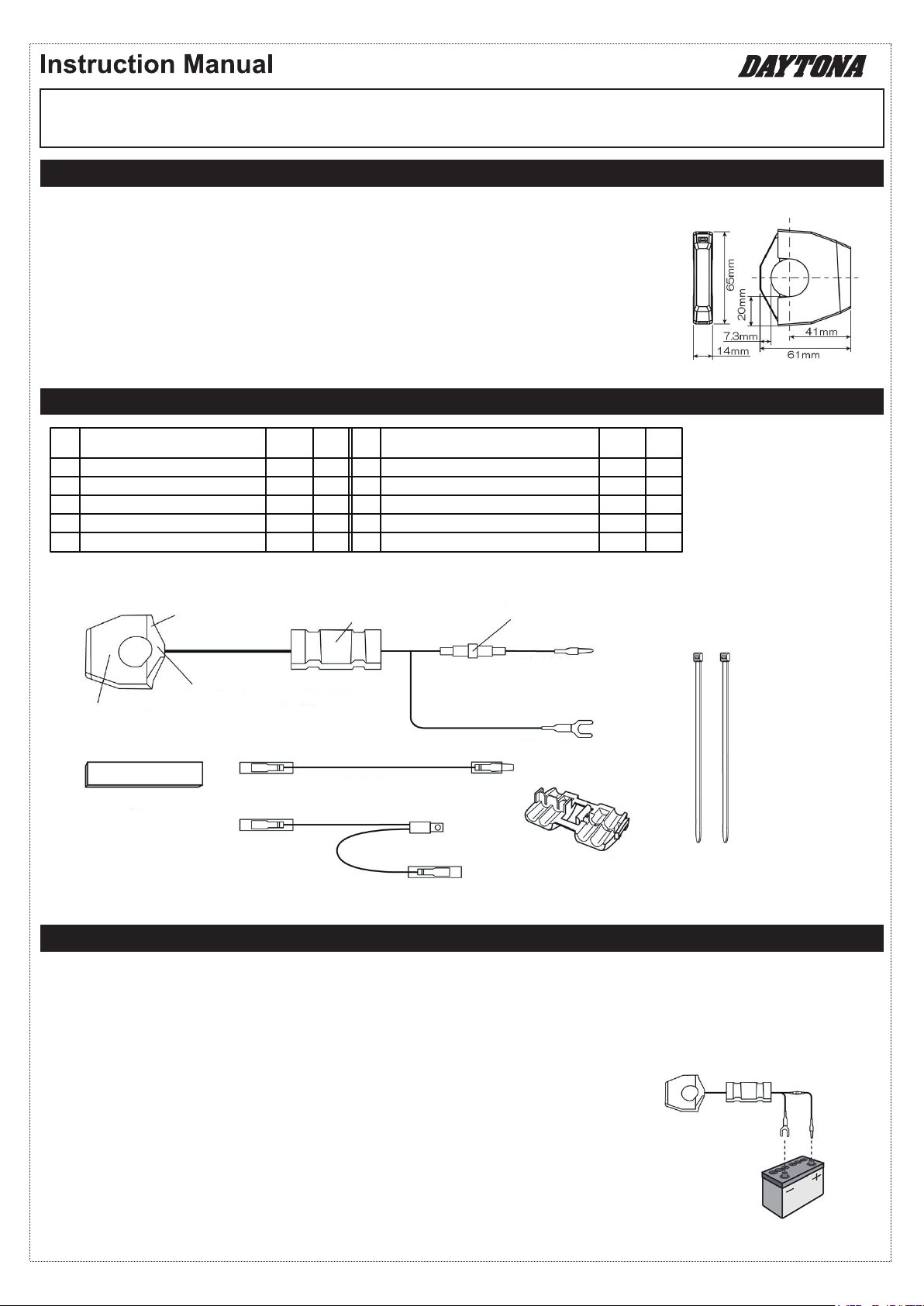
USB power supply body
Underbracket ※Installed
Transformer ※Installed
Screw ※Installed
Rubber band (t=2.0, 1 spare)
No. Part name Size
(mm) Qty
⑥
⑦
⑧
⑨
⑩
①
②
③
④
⑤
Extension wire harness
Brake switch branching wire harness
Wire connector (※1)
Cable tie
Glass tube fuse (※2) ※Installed
14×70
1200
270
150mm
3A
1
1
1
1
2
1
1
1
2
1
No. Part name Size
(mm) Qty
SLIM-MOUNT USB #89371 (98437) 1PORT 2.4A (ACC)
#89372 (98438) 2PORT 4.8A (ACC)
PRODUCT FEATURES
COMPONENTS
INSTALLATION
● Dedicated 12 V DC automotive device.
● The thin body of this USB power supply provides a sleek fit to the vehicle.
● The single-port USB power supply has an output of 5 V, 2.4 A × 1.
The dual-port unit has an output of 5 V, 2.4 A × 2.
● Easily connect the wiring with the included brake switch branching wire harness.
(※Except for some switches)
● The clamp is compatible with handlebar diameters of 22.2 mm / 25.4 mm.
● Safe design with 3A fuse.
● Overcurrent protection feature.
● Reversed-connection prevention feature. (fuse blows and input current is cut)
【Precautions 】
● For details on removing and installing vehicle parts, etc., refer to the service manual published by the vehicle manufacturer.
● Secure the vehicle on a stable location so that it will not fall over while being worked on,
and ensure the safety of your environment while working.
● Before starting work, refer to the following diagram and check the operation of this product.
● Disconnect the cable from the negative battery terminal on the vehicle.
※1. Compatible wires: 18–14 AWG, 0.75–2 sq ※sq = (JIS) Cross-sectional area (mm2)
①USB power supply body
②Underbracket (※Installed)
③Transformer
④Screw (※Installed)
⑤Rubber spacer
⑥Extension wire harness
⑦Brake switch branching wire harness
⑧Wire connector ⑨Cable tie (2pcs)
⑩Glass tube fuse (3A/ Installed)
+ (Red)
- (Black)
[ Pre-installation check ]
● Connect +(Red) wire to the positive post of the battery and –(Black) wire to the negative post.
Then check that this product operates correctly.
※ Be careful, the reversed-connection prevention feature will cause the fuse to blow.
1/4
[Dimensions]

【Installing USB power supply body ① on Φ22.2 mm handlebar 】
03. Wrap the rubber band ⑤around the space provided in steps 01 and 02.
※ The rubber band ⑤ cannot be used with a Φ25.4 mm handlebar.
2/4
[Sample installation:
Between clutch master cylinder and handlebar switches]
※ Be aware of the vehicle wiring.
※ Make sure that there is no improper
contact with the lever or other parts.
Adjust the positions of
the clutch master cylinder,
handlebar switches, etc.
Provide a space of
15 mm or more.
[Assembling the USB power supply body] [Assembly precautions]
Φ22.2 mm handlebar(※3)
Opening
①USB power supply body ② Underbracket
④Screw
Tab
⑤ Rubber band(※3)
※3...Cut to adjust the length to the installation location.
On a Φ25.4 mm handlebar (or pipe), install without the rubber band ⑤.
※ When installing beside the master cylinder or handlebar switches, be sure not to pinch the wires of switches and other electrical
components. Also, make sure that the lever, when fully squeezed, does not come into contact with the product.
Turn the handlebar to the left and right to check that the wires are not pulled.
①USB power supply body
② Underbracket
Opening
Tab
04. Use the screw ④ to temporarily assemble the USB power supply body ①and underbracket ②onto the rubber band ⑤.
At this time, insert the tab on the underbracket ② into the opening in the USB power supply body ①.
※ Remove vehicle parts if necessary for performing the work.
※ Be sure not to pinch any wires.
05. Slowly tighten the screw ④ until the USB power supply body ① can no longer turn.
※ Be sure not to overtighten the screw ④. Since the product is made of resin,
tightening the screw more than necessary may cause the resin to crack or may damage the screw threads.
【Connecting power supply wires 】
When using the brake switch branching wire harness ⑦ to supply + power
06. This can be used if the connector of the wire connected to the brake switch is L-shaped as shown in the diagram.
※ This cannot be used if the connection is made with a coupler. In that case, skip to step 17.
07. Connect the cable to the negative battery terminal. Of the two wires connected to the brake switch,
use a tester to identify the wire that carries 12 V when the ignition switch is turned on. After confirming,
turn off the ignition switch and disconnect the cable from the negative battery terminal.
※ If incorrect connections are made, abnormal operation, such as power being supplied only when the brake is applied, will occur.
08. Refer to the diagram below and connect the brake switch branching wire harness ⑦ to the wire identified in step 07.
【 Checking the installation location 】
01. The thickness of the USB power supply body
is 14 mm. Provide a mounting space of
approximately 15 mm on a straight part of
the handlebar.
02. During installation, refer to the diagram below
and make sure that no parts will come into contact
with the USB power supply body within
the provided space.
※ If there are parts that may come into contact with
the product, make adjustments to the vehicle
or install at a different location.

When the brake switch branching wire harness ⑦cannot be or is not used
09. Connect the + wire (red) of the USB power supply body ①to the brake switch branching wire harness ⑦.
If the + and – wires of the USB power supply body ①are reversed, the reversed-connection prevention feature will cause
the fuse to blow. If the fuse blows, replace the fuse.
10. Connect the cable to the negative battery terminal. Use a tester to identify the location where the – battery cable (ground) is
connected to the vehicle with an M6 or smaller bolt. After identifying the ground, disconnect the cable from the negative battery
terminal.
※ The location of the – battery cable (ground) is where the resistance is nearly 0 Ω.
11. Fasten both the – wire (black) of the USB power supply body ①and the – battery cable (ground) identified in step 10 with the bolt.
12. Use a cable tie ⑨to secure the transformer ③to the vehicle.
13. Connect the cable that was disconnected before performing the work to the negative battery terminal.
14. Install any vehicle parts that were removed before performing the work.
15. Turn the handlebar to the left and right to check that the fuse holder wires are not pulled and that no parts come into contact with
the product.
※ A pulled wire can lead to problems such as sudden operation failure.
16. Check that there are no abnormalities; if there are no problems, the work is completed.
17. Connect the cable to the negative battery terminal. Use a tester to identify the wire that carries 12 V when the ignition switch is
turned ON. After confirming, turn off the ignition switch and disconnect the cable from the negative battery terminal.
18. Cut the male connector end of the extension wire harness ⑥to adjust its length.
19. Use the wire connector ⑧to connect the extension wire harness ⑥to the wire identified in step 17.
※ For details on using the wire connector ⑧, refer to the diagram below.
3/4
[Branching the brake switch power supply] [NG]
To the + wire (red) of
the USB power supply body ①
Wire that carries 12 V when the ignition switch
is turned ON.
※Incorrect installation will cause
symptoms such as power being supplied only
when the lever is squeezed.
※Cannot be used if the connection is
made with a coupler. Go to step 17
⑦Brake switch
branching wire harness
Brake switch
[Sample power supply wire connection] [Using the wire connector ⑧]
⑥Extension wire
harness
Cut
Connect with wire
connector ⑧, etc.
Wire that carries 12 V
when the ignition switch
is turned ON
⑥Extension wire harness
Pliers
⑧Wire connector
⑥Extension wire
harness
Wire that carries 12 V when
the ignition switch is turned ON
20. Connect the + wire of the USB power supply body ①to the extension wire harness ⑥.
If the + and – wires of the USB power supply body ①are reversed, the reversed-connection prevention feature will cause
the fuse to blow. If the fuse blows, replace the fuse.

【Troubleshooting 】
4/4
Symptom
21. Connect the cable to the negative battery terminal. Use a tester to identify the location where the – battery cable (ground) is
connected to the vehicle with an M6 or smaller bolt. After identifying the ground, disconnect the cable from the negative battery
terminal.
※ The location of the – battery cable (ground) is where the resistance is nearly 0 Ω.
22. Fasten both the – wire (black) of the USB power supply body ①and the – battery cable (ground) identified in step 21 with the bolt.
23. Use a cable tie ⑨to secure the transformer ③to the vehicle.
24. Connect the cable that was disconnected before performing the work to the negative battery terminal.
25. Install any vehicle parts that were removed before performing the work.
27. Check that there are no abnormalities; if there are no problems, the work is completed.
26. Turn the handlebar to the left and right to check that the fuse holder wires are not pulled and that no parts come into contact with
the product.
※A pulled wire can lead to problems such as sudden operation failure.
Solution
Not charging
Charging may
stop.
Cause
Make sure that the USB cable is not damaged.The USB cable is damaged.
No power is supplied.
There is improper contact
with wires of other parts.
Make sure that 12 V DC is supplied at the + wire connection.
Make sure that the – wire is connected to the ground.
If the fuse blows immediately after being replaced, the main unit may be damaged.
Gather your purchase information and consult your retailer.
In rare cases, the fuse may blow if the product is supplied with high-voltage power. Consult with
the vehicle retailer to make sure that there are no problems with the electrical system of the vehicle.
Check the wire connections of each part.
A wire of a part or the USB
cable is bent at a sharp angle.
If a wire or cable is held in place bent at a sharp angle, the electric current may not flow correctly.
Reroute the wire to provide sufficient slack.
The rated capacity of
the output is exceeded.
The capacity is maximum 12 W (5 V, 2.4 A) for each port. Check the rating of your electronic devices.
※If the output rating is exceeded, the power will be cut.
A wrong type of USB cable
is used.
Certain mobile phones may not charge unless a communication cable is used. Check the USB cable.
There is improper contact
at the USB port.
Make sure that there is no improper contact at the USB port or in the USB connection with the connected
device.
There is improper contact
with wires of other parts. Check the wire connections of each part for improper contact.
The fuse holder wires are
subjected to strong tension.
Make sure that the fuse holder wires are not pulled when the handlebar is operated or while riding.
In case of tension, reroute the wire.
The voltage drops when
the engine is started.
Certain mobile phones may interpret the voltage drop that occurs when the engine is started to be
abnormal and stop charging. Connect the electronic device to the USB port after starting the engine.
The transformer
becomes hot.
If the transformer is installed near a heat-generating source, the operating temperature will be exceeded
and output may stop. Change the installation location of the transformer.
The USB cable is damaged. Make sure that the USB cable is not damaged.
There is improper contact
at the USB port.
Make sure that there is no improper contact at the USB port or in the USB connection with the connected
device.
The transformer is
exposed to interference.
Is the transformer installed near a noise-generating part? The transformer may be malfunctioning due to
interference. Take measures against noise such as changing the installation location of the transformer
or wrapping it with aluminum tape that is grounded.
The transformer is exposed
to interference.
Is the transformer installed near a noise-generating part? The transformer may be malfunctioning due to
interference. Take measures against noise such as changing the installation location of the transformer
or wrapping it with aluminum tape that is grounded.
The fuse blows.
Make sure that the power supply wires are not reversed.
The charging
indicator is on,
but the charge
does not
increase
or decrease.
The battery charge
drops quickly
during long-term
storage.
The connected electronic
device is hot.
Is your electronic device abnormally hot? If software is used at the same time that the device is being
charged, a protection function on some devices may be activated to reduce the charging current.
Temporarily stop using the device. ※This is likely to occur when the electronic device is used in
midsummer and exposed to direct sunlight.
The transformer
becomes hot.
If the transformer is installed near a heat-generating source, the operating temperature will be exceeded
and output may stop. Change the installation location of the transformer.
The power supply wire is
connected to an unswitched
wire.
This product consumes a small amount of standby power, even when no electronic device is connected to
a USB port. The consumption is small, but battery depletion will be faster than usual if the battery is weak
or during long-term storage. Connect the + wire to the wire that carries 12 V when the ignition key is
turned on.
A wire of a part or the USB
cable is bent at a sharp angle.
If a wire or cable is held in place bent at a sharp angle, the electric current may not flow correctly.
Reroute the wire to provide sufficient slack.
This manual suits for next models
3
Table of contents
Other Daytona Motorcycle Accessories manuals


Popular Motorcycle Accessories manuals by other brands

hepco & becker
hepco & becker Engine guard Mounting instructions

hepco & becker
hepco & becker 630790 Assembling instructions

MadStad Engineering
MadStad Engineering GL1800 quick start guide

ScorpionExo
ScorpionExo COVERT X manual

Black Diamond Equipment
Black Diamond Equipment HALF DOME Instructions for use

LSL
LSL SC59 FITTING INSTRUCTION


