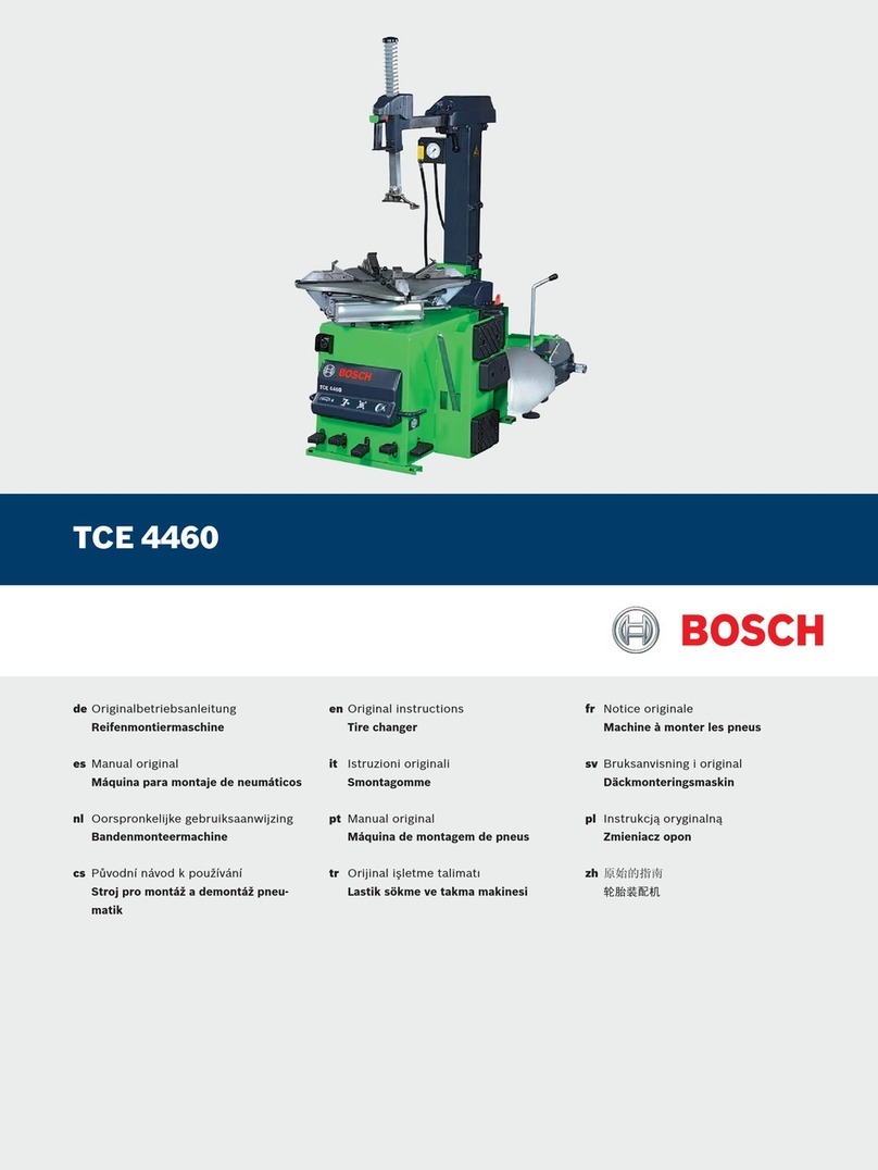
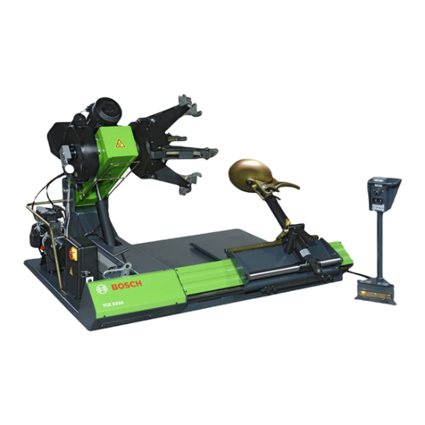
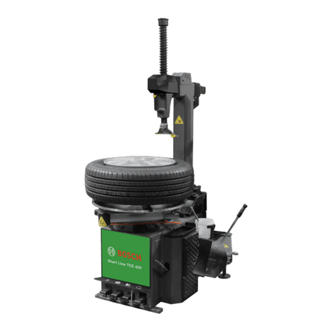
Bosch TCE 260 User manual

TCE 260
操作手册
拆胎机
zhen
Operation manual
Tyre changer

1 987 AT7 374 2015-09-02| Robert Bosch GmbH
2 | TCE 260 |

1 987 AT7 374 2015-09-02| Robert Bosch GmbH
4 | TCE 260 |en
Content English
1. Outline 5
1.1 General provision 5
1.2 Technical Parameter 5
1.3 Application range 6
1.4 Machine diagram 6
2. Safety requirements and notes 7
2.1 Usage 7
2.2 General safety precautions 7
3. Transports 8
3.1 Transport and packing 8
3.2 Transport and storage
environment requirements 8
3.3 Transport method 8
4. Unpacking 8
4.1 Unpacking 8
4.2 Transports 9
4.3 Assemble 9
5. Installation 10
5.1 Installation 10
5.2 Fix of the machine 11
5.3 The connection of the air supply
and power supply to the machine 11
5.4 Test control system 12
6. Operation 12
6.1 Safety notice 12
6.2 Check before operation 12
6.3 Special tips 13
6.4 Operation notice 13
6.5 Separate the tire edge 13
6.6 Rim location direction 14
6.7 Fixed the tire 14
6.8 Demount tire 15
6.9 Mount the tire 16
6.10 The process for mount/ demount
the special wheel 18
7. Inflation 18
7.1 Warning 18
7.2 Vacuum tire inflation 18
7.3 Inflate the tubed tyre 18
7.4 Tire pressure 19
8. Transport, Storage, and Ruin 19
8.1 Transport 19
8.2 Storage 19
8.3 Ruin 19
9. Maintenance 19
9.1 Warning 19
9.2 Maintenance operations 20
9.3 Use of the oil 21
10. Troubleshooting solution 21
11. Pneumatic scheme 22

Outline | TCE 260 | 5 en
1 987 AT7 374 2015-09-02|Robert Bosch GmbH
1. Outline
1.1 General provision
1. This instruction is essential part for products. Please
carefully read the warnings and instructions inclu-
ded in manual before operation which also provide
important information regarding safety usage and
maintenance.
2. Properly keep this manual for the reference in the
future.
3. Careful reading the manual to make the operator use
the machine correctly, the dealer will provide long-
term and effective after-sales services. The producer
and dealers will not be responsible for the problems
caused by any incorrect operation.
4. Notes included in this manual:
RDanger: The process can directly cause the serious
damage or death.
RWarning: The unsafely process maybe cause the ligh-
ty or serious damage.
RNote: The unsafely process can cause the serious
damage or death.
5. Before connect the power supply and air supply,
please carefully read the manual. Keep the operation
notes and warning notes on the manual and machi-
ne. The related information and data in the sales
process should be carefully kept. Different machine
will be equipped with different instruction manual.
The operators should pay attention to the effectiven-
ess of the manual.
Danger
You must use the machine in accordance with the requi-
rements specified in the manual. The manufacturer and
dealers won’t be responsible for the problems caused
by any incorrect operations.
Warning
The machine must be operated by the professional
personnel. The operator must be fully understand the
manual and received the professional training. If the
nonprofessional personnel operate the machine, which
maby because the personal dangerous and also lead to
the damage to the tire and rim.
Notes
The pictures in the manual all comes from the original
design structure of the machine. The structure shown
may be different from the actual structure of the machi-
ne.
The machine is made for the purpose to give guidance
to the personnel with some basis of mechanical and
electrical skills. Therefore, the basic processes such
as how to fix the bolts may be omitted. Do not try to
letting the personnel without experience operate the
machine. If you have any requirement related to this,
please ask the dealer to provide the help.
1.2 Technical Parameter
1. Overall dimension
Overall dimension
Length A=1120mm
Max. length A1=1740mm
Width B=1050mm
Max. width during
operation process
B1=1550mm
Min. height H=1710mm
Max. heigt H1=2170mm
Applicable wheels: standard tire, reverse tire, tire without center
hole, run flat tire.
2. Range of application
!This machine is applicable for following range of
wheels:
Range of wheels
Outside clamp 10"~22"
Inside clamp 12"~26"
Max. tire diameter 1050mm
Max. tire width 13"
3. Turntable styple
Turntable style
Plying-up style Jaw
Fix style Jaw
Clamping style Pneumatic
Drive style Motor
Torque force 1100Nm
Turntable rotation speed 6rpm

1 987 AT7 374 2015-09-02| Robert Bosch GmbH
6 | TCE 260 | Outline
4. Decompression system
Decompression system
Decompression tool Bead breaker blade
Fixed style Manual
Enter style Manual
Max. working size 340mm
Bead breaker
blade pressure
2500KG
5. Power
Power
Single phase 220V/110V-1.1kW 50Hz/60 Hz
Three phase 380V-0.75 kW 50Hz
Air supply pressure 8-10bar
6. Noise< 70dB
1.3 Application range
The equipment is pneumatic/electic tyre changer. The
workable range (weight/size) please refer to the Chap-
ter of Technical parameter.
RApplicable tire types:
$Tire standard tire
$Reverse tire
$Tire without center hole
$Run flat tire (with assist arm)
Warning: Each type of tire has its professional
operation method.
RNotice: When demount/mount the tire of the old car(
exceeding 30 years)/modified car tires/ tire with the
rim modified, it may cause the accident.
1.4 Machine diagram
Warning
Understand all the information related to the machi-
ne; understand how to prevent the appearance of the
accident; understand how to use the tire changer;
understand all the function; understand the entire con-
trol key; understand each operation process to avoid
accident.
The installation of the machine must be correct: opera-
tion correctly and also execute the maintenance perio-
dically.
REquipment structure
1-Hexagon shaft: fixed demounting head
2-Cover: dust prevention
3-Cross arm locking control valve: locking/unlock swing arm and
horizontal arm
4-Demounting head: the tool for demounting/mounting the tire
5-Clamp jaw: clamping the rim
6-Turntable: fixed the tire
7-Pedal control system
7-1Swing arm control pedal: control swing of the horizontal arm
7-2Clamping jaw control pedal: control open/close of the clam-
ping jaw
7-3Blade control pedal: control the blade movement
7-4Turntable rotation control peda: control the rotation of the
turntable
8-Bead breaker blade: decompress the rim of tire
9-Shovel arm: support bead breaker blade
10-Grease container breaker: convenient to install different grea-
se container
11-Column: support horizontal arm
12-PCL Inflation gun: inflating for the tire
13-Air treatment assembly
13-1Pressure reducing valve: adjust the air supply pressure
13-2Water separator: separate the water
13-3Atomized lubricator: provide oil for the air route
en

Safety requirements and notes | TCE 260 | 7 en
1 987 AT7 374 2015-09-02|Robert Bosch GmbH
RMachine nameplate
$Each machine is equipped with the appointed
technical parameter and serial number.
Warning
It is prohibited to dismantle the nameplate on the ma-
chine.
REach machine is equipped with the appointed techni-
cal parameter and serial number.
Symbol Meaning
V Voltage supplied to the machine
A Rated current when the ma-
chine is running
Kw Power
Hz Frequency
Ph Phase of power supply
bar Operating air supply pressure
Serial N. Machine’s serial number
ISO 9001 Certified management system
CE CE safety marks
RThe completed information of machine model and
serial number will be helpful for our technical per-
sonnel to provide you with the service and technical
support and also make it more accurate and easier
to change the parts. If there is difference between
the data in the manual and the data on the name-
plate, the one on the nameplate should be conside-
red to be correct.
2. Safety requirements and
notes
2.1 Usage
1. This machine is used to demount/ mount the car
tire. The dimension of the rim is 10”-26”. The max
diameter of the wheel can reach 1050mm.
2. Any other usage will be incorrect.
3. Special statement: the manufacturer will not bear
any responsibility to any damage arising from the
operation not specified in the manual.
2.2 General safety precautions
1. This machine can only be operated by the authorized
personnel who have received special training.
2. The manufacturer will not bear any responsibility
to any direct or indirect damage arising from the
modification to the machine without the permission
of the manufacturer.
3. When the machine is delivered out of the factory,
which is equipped with the complete instruction
manual and warning signs. If they are damaged or
ruined for some reasons, please ask the manufactu-
rer to change.
4. The machine should be kept away from the inflam-
mable and explosive materials. It should also be kept
from sun and glare. The place to place the machine
should be good ventilation.
5. Make sure to use the original parts and accessories.
6. The machine should be installed by the authorized
personnel as per the manual.
7. During operation, you should pay attention whether
there is any danger. Once you find the danger, stop
the machine at once and contact the dealers.
8. When the machine is running, the unauthorized per-
sonnel should be kept away from the machine.
9. The operator should wear the protective equipments
such as gloves, goggle and overalls to prevent the
accidental injury.
Warning
Secure that the grounding of the machine is perfect.
Warning
When operate the machine, the unauthorized personnel
should be kept away from the machine.
Warning
Non-compliance to the operation requirement or the
warning requirements related to the danger specified
in the manual will cause the injuries to the operators
or personnel nearby. Before connect the machine to
the power supply, please carefully read the manual and
warning notes. The machine must be operated by the
profession personnel. The operator must have received
special training and understood the requirement in the
manual. He or she should also understand related safe-
ty requirement and detailed requirement in the process
of operation. The operator must not operate the machi-
ne after drinking.
RThe operator must pay attention to:
$Understand all the requirements specified in the
manual;
$Understand the function of the machine;
$Unauthorized personnel should be kept away from
the machine;
$Secure the installation of the machine should
comply with the related local law and regulation;
$Secure that the operators have received the trai-
ning and have the skill to operate the machin, and
they must be monitored;
1 987 AT7 374 2015-09-02| Robert Bosch GmbH
8 | TCE 260 | Transports
$Do not detach the bolts, nuts or the other compo-
nents from the machine;
$Before cut off the power supply, you must not
contact the motor and the live parts on the machi-
ne such as power cord;
$Carefully read the manual and learn how to use
the machine correctly and safely;
$Keep the manual for the future reference.
Warning
Do not detach the danger decals, safety warnings and
operation tips on the machine. If there is any damage,
please contact the local dealer in time.
$During the process of use and maintenance, the
operator should pay attention to the danger of the
high electrical voltage.
$Do not modify the machine or use the non-original
parts unauthorized.
$The operators must wear tight overalls, gloves,
goggle or safety shoes etc.
Warning
When the operator makes operation or maintenance,
it is forbidden to wear loose clothes, necklace or long
hair.
3. Transports
3.1 Transport and packing
The machine should use the original package and then
be transported. The package should comply with the
following requirements.
RThe package size requirement:
Package size
Width 1150 mm
Length 1200 mm
Height 1050 mm
3.2 Transport and storage environment
requirements
Temperature : -25°- +55°C.
Warning
Do not place any other objects on the carton.
3.3 Transport method
As shown in the figure,
Open the top package, plug the fork of the forklift from
bottom of the original package.
Note
Keep the original package for the future transporting.
4. Unpacking
4.1 Unpacking
1. When unpacking, the operator should wear the pro-
per protective tool such as gloves.
2. Carefully check the packing list of the machine to
see if there is any mistake related to the quantity of
the parts. If there is any mistake, please contact the
dealer at once.
3. The objects in the carton, such as board, nails,
screws and plastic bags, should be located at the
safe place.
4. If there is any pollutant or the indecomposable sub-
stances, you should treat them as per the regulation
specified in t he local laws and regulations.
Warning
During the process of unpacking, assembly and trans-
porting, you should follow the following requirements
and handle with care. Or it will damage the machine.
5. Detach the upper cover of the carton and make sure
whether there is any damage or not during trans-
porting. Find the fix bolt to fix the machine on the
pallet and prepare to shift out the machine.
en

Unpacking | TCE 260 | 9 en
1 987 AT7 374 2015-09-02|Robert Bosch GmbH
4.2 Transports
1. Hoist up the machine from the pallet. Bind the hoist
tape (mod.DR 750 of 3 m and DR 735 of 1.5 m factor
6:1 ). Hoist tape requirement: more than 1 metric
ton and safety factor 6:1.
2. No matter when to move the machine, you should
take above methods.
3. You cannot move the machine if the machine is not
cut off from its air supply and power supply.
4.3 Assemble
1. Lifting the cross arm to the machine body. As shown
in figure below:
RPut the air pipe that inside column into the machine
body.
RFixed the position of machine, then put the fixed
axis insert the linked hole by hammer then fasten.
RAxis connect the bead breaker cylinder and vertical
column, then fixed.
Note: All above processes must be finish on the pallet,
don’t loosen the bolt; and during moving period, please
make the cross arm stable until finish to assemble.
2. Before lifting the complete machine.

1 987 AT7 374 2015-09-02| Robert Bosch GmbH
10 | TCE 260 | Installation
RFixed the cover then fasten the bolt.
RConnect the air pipe, open the side panel of machine
body, then make the air pipe connect with straight
connector.
RAssemble the bead breaker blade, then fasten the
bolt.
RLoosen the anchor bolt, push the cross arm to the
innermost position, prepare the lifting machine.
Note: The way to lifting the machine, please refer to the
figure, please keep stable while lifting the machine(the
machine center isn’t same with the gravity center) and
protect the plastic cover from damage.
5. Installation
5.1 Installation
1. Installation environment requirement:
Requirement
Temperature 4-40ºC
Sea level <1000m
Humidity 50%40ºC-90%20ºC
2. When you choose the installation position, you
should secure the safety of the machine when it runs
in the normal work condition.
3. This machine must be connect to the main and com-
pressed air system, hence we suggest you to install
the machine near the power source.
4. Installation position should at least leave the space
in the following figure to secure free movement of
each part of the machine.
5. If this machine is installed outdoors, you should take
measures to prevent rain and sun. General speaking,
this machine can not be used outdoors.
en

Installation | TCE 260 | 11 en
1 987 AT7 374 2015-09-02|Robert Bosch GmbH
6. The work are should enjoy enough light to secure the
operators can observe each details of the operation.
Besides the operator, when the machine is run-
ning, any other personnel should not in the work area.
5.2 Fix of the machine
1. Detach the bolts and nuts fixed on the machine
chassis. Bind the hoist tape (mod. DR 750 of 3m and
DR 735 of 1.5m factor 6:1).
2. Lift up the machine.
3. Take out the pallet and position at the preselected
location.
Pay attention that the nozzle and air hose on
the machine should not be damaged during the process
of hoist. Pay more attention when hoist up the machine.
When inflate the tire on the turntable, you must
fix the machine on the ground.
4. Use the M10 bolt grade 12.9, via the hole at the pal-
let, to fix the machine on the ground.
5.3 The connection of the air supply and
power supply to the machine
1. Connect the machine to the electrical circuit. As
per the electrical power specification, the electrical
circuit must be equipped with the fuse and perfect
grounded earth wire and also a protective switch will
be connected.
Note: If the machine is lack of the plug, the user should
prepare a 16A plug adapted to the machine’s operation
voltage as per the electrical power norm.
RThe voltage deviation should be 0.9-1.1 time of rated
voltage range, and the frequency deviation should be
0.99-1.01 time of rated frequency range. You should
take the necessary protective methods.
RThere must be professional personnel to be respon-
sible for the connect of the electrical circuit.
RThe electrical net in the working area should be relia-
ble grounded.
RWhen you do not use the machine, please switch off
the power supply in time to secure the machine not
to be used accidently.
RIf the machine will not be used for a long time and
the machine is directly connected to the electrical
cabinet not via a plug, the electrical cabinet should
be locked. Only the professional personnel can open
it to secure the machine not to be used accidently.
Warning
The machine must be grounded and do not connect the
earth wire to the heater, plumbing and telephone cable
etc.
2. Secure the compressed air supply comply the requi-
rement of the machine. The details of these require-
ments are specified in chapter “Technical parame-
ter”. The pressure and flow of the air supply should
meet the requirement of using the machine. And the
pressure ranges from 8 to 16 bar.
3. Use the special air hose to connect with the water
separator, air regulator and lubricator at the side
of the machine. Please see the figure. Please make
sure that the oil has been fully filled reaching the
standard oil level. The oil contained in the lubrica-
tor should be SAE20 oil, or the air route will not be
lubricated and the sealing kits will be damaged in a
short time.
RThe user must mount a air supply cut off valve and
pressure regulation valve in front of the machine.

1 987 AT7 374 2015-09-02| Robert Bosch GmbH
12 | TCE 260 | Operation
5.4 Test control system
1. Pedal control system
$Step down the turntable rotation control pedal
7-4, the turntable will rotate clockwise. And rise
up the turntable rotation control pedal 7-4, the
turntable will rotate counterclockwise.
$Step down the horizontal arm control pedal 7-1
to the lowest position and the horizontal arm will
swing out. Go on to step down the horizontal arm
control pedal to highest position the horizontal
arm will swing back to the vertical position.
$Step down the blade control pedal 7-3, the blade
will work and release the blade control pedal 7-3,
the blade will back to its original position.
$Step down the clamping jaw open/close control
pedal 7-2 to the first gear and the clamping jaw
will open. Step down the clamping jaw open/
close control pedal 7-2 to the second gear and
the clamping will stop at any moment and Step
down the clamping jaw open/close control pedal
7-2 to the third gear and the clamping jaw will
close.
$If the horizontal arm at the inmost position,
horizontal will be released and tool head will fall.
When at the middle position, horizontal arm will
be released and tool head will rise up. When at
the outmost position, horizontal arm and tool
head will be locked.
2. Air treatment assembly
$Pressure reducing valve 13-1: Pull out the knob at
the top end of pressure reducing valve A. Clock-
wise/counter clockwise turning can adjust the
feeding pressure of the machine. Press down the
knob A after adjustment.
$Water separator 13-2: Clockwise/counter clock-
wise turning knob B at the lower end of water
separator can deflate the water in the water cup.
$Lubricator 13-3: Turning the knob at the top end
of the lubricator. Clockwise/counter clockwise
turning can adjust the oil feeding speed of the
lubricator.
3. Note
$The pressure of the machine should he adjusted
in the range of 8-10bar.
$Regularly deflate the water in the water separator.
$Move back and forward the blade cylinder and
observe the condition of lubricator. Guarantee the
oil will be fed before operation each day.
6. Operation
6.1 Safety notice
RThis machine is only used to mount/demount the car
tires.
RThe instruction manual must be correct. It is the
integrated part of the machine.
Warning
It is prohibited to use this machine to do the other
work.
The machine is equipped with the tire inflation system.
This function is an independent one. You should pay
more attention to this. Refer to the Chapter "Inflation".
Warning
You must use the original parts of the manufacturer.
Warning
You should keep your hand far away from the point to
be crushed.
Warning
When the accident appears, you should stop the run-
ning of the machine at once.
1. Plug out the power plug.
2. Switch the air supply.
6.2 Check before operation
1. Each time before operate the machine, you should
make the bead breaking cylinder run back and
forward to observe the lubricator and make sure
it starts supply the oil to the air route. After you
confirm that the lubricator works normal, you can
guarantee each part of the air route system under
perfect lubrication.
2. Check the air treatment assembly to guarantee the
pressure indicated on the pressure gauge of the
pressure reducing valve is not less than 8bar.
3. Check whether the power supply connection is right
or not.
en

Operation | TCE 260 | 13 en
1 987 AT7 374 2015-09-02|Robert Bosch GmbH
6.3 Special tips
1. Special process to be need for some special tires,
which different from the normal demount/ mount
process.
2. Some special rims as figure below, the groove at
the middle of the rim is very shallow. Or there is no
groove. These rims can not meet the safety regulati-
on regarding the traffic and transportation. In some
countries, these types of rim/wheel are not allowed
in the market.
Danger
Pay special attention when demount/ mount tire, the
rim or tire may be damaged.
3. In the process of inflating the tire, the danger of tire
burst may happen.
4. The cross-section shaft of some rims is the smooth
structure as figure below. The C at rim is very deep.
You will find B is higher than A. When you break the
bead of this type of tire, you must press the bead
which must be lower than B position. When mount
the tire, the bead opposite to the tool head must
over B point. At this moment, the bead can be led
into the groove at the middle of the rim.
5. Some wheels have the tire pressure inspect system
as figure below. Do not damage the tire pressure
inspect system when mount/demount tires.
6.4 Operation notice
Warning
The following information must be read, which is hel-
pful to operator to simplify operation processes and to
reduce unnecessary troubles.
RTips:
To protect the rim, demounting head plastic conver
should changed per two mouth. If damaged, these plas-
tic parts should be changed at once.
Warning
Bead breaking process is very danger, the operator
should operate accordance with the instruction descri-
bed in the manual.
6.5 Separate the tire edge
Before any operation, please detach the weight
attached on the wheel before deflate the tire.
Not using the grease will seriously damage the
tire. Please use the special grease.
1. Check whether the tire has been deflated complete-
ly. If not, you should deflate at first.

1 987 AT7 374 2015-09-02| Robert Bosch GmbH
14 | TCE 260 | Operation
You should be very careful when you break the
bead. When the blade moves, its speed is very fast and
the strength is very strong. In the area of its moving,
any objects will be under the danger of being crushed.
The clamping jaw on the turntable should be closed
completely.
When the clamping jaw is opened, if the opera-
tor undertakes bead breaking, this process will cause
danger to the operator. In this process, the hand should
not touch the pressed surface of the tire.
2. Lean the tire against rubber wheel support.
3. The surface of the blade will keep about 1cm from
the rim and the blade should rightly face the tire.
Pay attention to the position of the blade to avoid it
from touching the rim after bead breaking.
4. Step down blade control pedal 7-3 to make the blade
start working. When the bead is broken, release the
pedal at once.
5. Rotate the tire until the edge of the tire is detached
from the rim and repeat at the other side.
6. Spread some grease on the tire.
Not using the grease that will seriously damage
the tire. Please use the special grease.
6.6 Rim location direction
How to decide from which side of the wheel to de-
mount tire?
1. When fix the wheel, the side of standard rim will
upward as figure.
2. Measure three dimension of A, B and C.
3. When fix the rim, the smallest size of C must be
positioned at the top position.
6.7 Fixed the tire
When the horizontal arm swings out, any one is
forbidden in the range of its movement.
RStep down pedal 7-1, swing out the horizontal arm
and clean the turntable.
When lock the tire, it is absolutely forbidden to
put your hand under the tire. To correctly lock the tire,
you should position the tire at the very center of the
turntable.
RClamp the rim from outside:
$Through step down the clamping jaw, open/ close
pedal 7-2 to control the open position of the
clamping jaw.
$Place the tire on the clamping jaw, keep pressing
down the rim. Step down the pedal 7-2 until the
rim is locked.
During you position the tire on the turntable,
one operator is enough if the weigh is less than 25kg. If
the weight is 25kg-50kg, 2 persons will be enough. And
you will use the tire lifting device if the weight is exceed
50kg.
en

Operation | TCE 260 | 15 en
1 987 AT7 374 2015-09-02|Robert Bosch GmbH
RClamp the rim from inside:
$Close clamping jaw on the turntable.
$Place the tire on the turntable, and step down the
pedal until the rim is locked.
Make sure rim is locked to the clamping jaw
firmly.
6.8 Demount tire
Position the duck head
1. Press the upper bead by hand to leave the space for
positioning the tool head.
2. Step down the horizontal arm swing out pedal to
move the horizontal arm to the work position.
3. Push the horizontal lock plate button to release the
hexangular shaft.
4. Move the tool head to the work position. The plastic
part at the head of the tool head should contact with
the rim.
5. Push the horizontal lock plate button to lock the
hexangular shaft.
Hook out the upper bead
1. Keep crowbar fixedly, reserve space for duck head.
If the space is not enough, please refere to Chapter
“Operation tips”
2. To guarantee bead breaking successfully, the opera-
tor can adopt Chapter "Operation tips" method.
3. Confirm the tire edge have fully catched by duck
head.
Note: If there is inner tube, please turn the valve 10cm
away to the right and then to operate. So that it can not
damage the inner tyre.
Demount the upper bead
1. Step down the pedal 7-4 and rotate the wheel until
upper bead is completely detached from the rim.
2. With the same process, you can rise up the lower
bead to help demount the upper bead.
3. During this process, if the bead slip back into the
groove of the rim, you can take the measures descri-
bed in Chapter "operation tip" to demount the upper
bead.
Demount the down bead(use duck head demounting)
1. If there have inner tube, which should remove inner
tube.
2. Use the same process for the down side tire until
demounting tire successfully.
3. Use crowbar to demount upper tire.
4. Step down pedal 7-4, rotate the wheel until fully
break away from steel rim.

1 987 AT7 374 2015-09-02| Robert Bosch GmbH
16 | TCE 260 | Operation
Move out the tire
RKeep the horizontal arm backward and move the tire.
6.9 Mount the tire
1. Selection the tire
$Before select the tire, you should know the tech-
nical feature, technical parameter, characteristic
and safe grade of the tire. The related information
is marked on the side wall of the tire.
Note
$Before mount the tire, please change the core of
the nozzle to be the nozzle of tubeless tire.
Note
$Confirm whether the related parameter of the tire
matches the parameter of the rim or not. And also
make sure the rim is not deformed and the center
hole not damaged. While you should also secure
that the surface of the rim without the phenome-
non of rusty and broken and there is not any bur
at the nozzle.
$Confirm the tire is under perfect condition and
without any damage.
2. Prepare the tire
$Lubricate the bead with the special tire grease.
$Place the tire on the rim with the tilt angle of 45
degree.
en

Operation | TCE 260 | 17 en
1 987 AT7 374 2015-09-02|Robert Bosch GmbH
3. Position the tool head
$Step down the pedal 7-1 to move the tool head to
the original work position.
Note: If you do not change the rim, the tool head will
automatically back to the correct working position.
4. Mount the bottom bead
$Position the bottom bead at the bottom end of
the head of the tool head, while at the top end of
the tail of the tool head.
$Use your hand to slightly press the tire to lead the
tire into the groove of the rim.
$Rotate the turntable clockwise to mount bottom
bead.
5. Mount the upper bead
$Position the upper bead at the bottom end of the
head of the tool head, while at the top end of the
tail of the tool head.
$Press the tire edge and lead the tire edge into
steel hook slot.
The tire edge can not slide out of the head of
the tool head.
Note: When you mount/ demount the tire, tire
rotates clockwise. If the tire is jamming during the pro-
cess, please stop working and counterclockwise rotate
the tire to remove the jamming.
Do not place your hand on the tire. When the
hexangular shaft comes back to its work position, the
hand between the rim and the tool head may be crus-
hed. Remove the objects may cause the danger to the
operators such as bracelet and loose cloth etc. To avoid
the accident, when the turntable rotates, you should
keep your hand and the other part of your body away
from the tool head as far as possible.

1 987 AT7 374 2015-09-02| Robert Bosch GmbH
18 | TCE 260 | Inflation
6.10 The process for mount/ demount the
special wheel
RSome special rims, the groove at the middle of the
rim is very shallow or without groove. As shown in
figure below:
RThe demounting process for the wheel, demount up-
per tire edge is different, the hook can’t fully catch
the suitable position, the operator need to find best
position according to operation situation, which can
be reduce resistance for wheel.
7. Inflation
7.1 Warning
Warning
The explosion may cause serious damage to the ope-
rator even death. So you should be more careful and
strictly follow the following use instruction. For the rea-
son that some protective devices are not designed and
manufactured, the operator must wear the goggles and
related protection.
Note
During operation, the noise may reach 85dB(A), so the
operator should wear the related protective devices.
Danger
The machine is equipped with inflation pressure limit
valve, but if the condition of tire and rim is not good or
the operation is incorrect, there is still the possibility of
tire burst.
Danger
Do not exceed the max pressure nominated by the ma-
nufacturer.
During the process to inflate, the operator should keep
away from the tire as far as possible.
1. Carefully check if the size of the rim is same to the
size of the tire.
2. Check the wear state of the tire or whether there is
damage or not.
3. During the process to inflate, frequently check the
pressure inside the tire.
4. The max. inflation pressure is 3.5bar, under any cir-
cumstance don't exceed manufacturer recommend
pressure.
5. The hand and body should be kept away from the
tire.
7.2 Vacuum tire inflation
1. Secure the rim is firmly fixed on the turntable and
the tool head and the tire pressing disk has been
kept asway from the tire. If possible, it should be
positioned to the farthest point.
2. Mount a new nozzle at the rim.
3. Secure the tire has been completely lubricated.
4. Take out the cup of the nozzle and clamp the gun at
the top end of the core to inflate the tire.
5. Frequently stop inflation and check the pressure in-
side the tire, not exceeding 3.5bar, until the pressure
inside the tire meet the requirement and avoid the
tire pressure not exceeding the max pressure.
6. Vacuum tire needs relatively large air flow. If air flow
is not enough, the bead should not transit the hump.
To increase the air flow, you can take out the core of
the nozzle. As figure, it is very good for the safety of
the car when in runs on the road.
7. Check. The junction between the bead and rim must
be perfect. If there is problem, you must deflate
the tire and repeat breaking bead and lubricate the
bead. Rotate the tire and then inflate the tire.
8. Attach the core to the nozzle.
9. Connect the inflation gun and then press the deflate
button to remove the residual air.
10. Mount the nozzle.
7.3 Inflate the tubed tyre
1. Secure the rim is firmly fixed on the turntable and
the tool head and the tire pressing disk has been
kept from the tire. If possible, it should be positi-
oned to the farthest point.
2. Secure the tire has been completely lubricated
3. Remove the nozzle, put the inflation gun head to
the air tap head, step down the inflation pedal then
inflate to tire.
4. Push the nozzle on the tube to deflate the air bet-
ween the tube and tire. Or the tube will be damaged.
en

Transport, Storage, and Ruin | TCE 260 | 19 en
1 987 AT7 374 2015-09-02|Robert Bosch GmbH
5. Frequently stop inflation and check the pressure in-
side the tire, not exceeding 3.5bar, un-til the pressu-
re inside the tire meet the requirement and avoid the
tire pressure not ex-ceeding the max pressure.
6. Attach the core to the nozzle.
7. Connect the inflation gun and then press the deflate
button to remove the residual air.
8. Mount the nozzle.
7.4 Tire pressure
1. Securing the correct tire pressure is very important
to the safety of the wheel.
2. The low tire pressure will cause the tire to be too
heat and with serious wear. And the life of the tire
will be shortening. The inside of tire will be damaged
and the oil consumption will be larger.
3. The high tire pressure will cause easy damage when
clamping and the tire wall will be seriously worn.
4. You must check you tire pressure one a week. You
should prepare a spare tire before you start a long
distance journey.
5. Check the tire pressure under the normal tire tem-
perature, not check when the tire temperature is too
high or too low.
6. Normal tire temperature means the vehicle has not
run for more than one hour or the run for not more
than 2-3km in low speed.
7. The tire pressure under normal tire temperature
should meet the requirement of the car and the tire
producer.
8. When the can is under heavy load, if the tire pressu-
re are not special specified, normally speaking, the
tire pressure will increase by 0.3bar.
8. Transport, Storage, and
Ruin
8.1 Transport
1. Switch off the air supply switch and power supply
switch.
2. Transport the machine as per the method in chapter
"Unpacking".
When you hoist the machine, you should not
damage the nozzle and air hose on the machine. Pay
mote attention to the process of hoisting machine.
8.2 Storage
If you want to store the machine for a long
time, you must secure:
1. Switch off the air supply and power supply and lubri-
cate the movable parts to prevent rusting.
2. The storage temperature is -25℃-55℃
3. The machine should be kept away from the inflam-
mable and explosive materials. It should also be kept
from sun and glare. The place to store the machine
should be good ventilation.
8.3 Ruin
If you want to ruin the machine, you must
secure:
1. Switch off the air supply and power supply.
2. Remove all the non-metal substances and treat them
as per the local law and regulation.
3. Collect the oil and treat them at the pointed place as
per the local law and regulation.
4. Ruin the other metal substances.
Environment:
The machine contains some substances which will
pollute the environment and cause the damage to the
human body if they are not treated properly.
9. Maintenance
9.1 Warning
Non-professional personnel should not under-
take maintenance.
RAs per the description in the manual, undertake the
maintenance periodically. This is very necessary to
prolong the life of the machine and guarantee the
normal work condition of the machine.
Do not undertake the periodical maintenance,
the reliability and operation of the machine will not get
guarantee and may cause danger to the machine, opera-
tor and the people nearby.
Before undertake any maintenance, you should
switch off the air supply and power supply. By repea-
ting stepping down the pedal, you can deflate the
residual air in the machine completely.

1 987 AT7 374 2015-09-02| Robert Bosch GmbH
20 | TCE 260 | Maintenance
RThe fault parts must be changed by the original parts
provided by the manufacturer.
Removing or breaking the safety devices such
as safety valve and standard nozzle violate the safety
standard.
Special note: The manufacture will not be
responsible for the claim arising from the apply of the
parts supplied by the other supplier and the damage
caused by removing or breaking the safety devices.
You should not modify the component on the
machine without authorized.
Note
RKeep the working area clean.
RDo not use the compressed air to blow off the debris
on the machine. Reduce the coming out of the dust
around.
9.2 Maintenance operations
RDo the following operation at least one time per 30
days.
1. Check the oil level in the oil cup. If the oil is not
enough, remove the oil cup and fill the lubrication oil
as shown in follow figure. The oil filled in the lubrica-
tor must be the special SAE20 oil.
2. The oil feeding speed regulation: Make the bead
breaking cylinder run back and forward to check
whether the oil feeding speed is one drop of oil per
2 travel of the cylinder. If not, use the bolt B to ad-
just as shown in follow figure.
3. Drainage: Check the water quantity in the water cup.
Turn/ press the valve at the low end of the water cup
to drain.
4. Each time before operate the machine, you should
make the bead breaking cylinder run back and for-
ward to observe the lubricator C and make sure it
starts feeding oil to the air route. After you confirm
that the lubricator works normal, you can guaran-
tee each part of the air route system under perfect
lubrication.
5. Periodically tighten the nut at the fixed equipment.
6. Periodically fill in the lubrication oil components can
move and slide to each other.
7. Periodically adjust the tension of the motor belt as
per the following steps:
$Before this operation, switch off the power supply
and air supply.
$Detach the side panel on the machine cabinet.
$Release the bolt A and nut C. Adjust the bolt B at
the back end of the motor bracket. Tighten the
belt as shown in figure below. The requirement to
the tension of the belt is that the belt will move
inward by 8mm if you apply the force of 8kg.
$After adjust, position the belt and tighten bolt A
and tighten nut C.
$If the tool head is not locked or not located at the
position 2-3mm higher than the rim, it is necessa-
ry to adjust the adjusting nuts A and B at the front
end of hexangular shaft lock plate.
$If the tool head is not locked or not backward
by 2-3mm, it is necessary to adjust the adjusting
nuts A and B at the front end of quartet lock
plate.
en
Table of contents
Other Bosch Tyre Changer manuals

Bosch
Bosch TCE 4510 User manual

Bosch
Bosch TCE 5210 Setup guide

Bosch
Bosch TCE 4460 User manual

Bosch
Bosch TCE 4540 User manual

Bosch
Bosch TCE 4225 User manual

Bosch
Bosch TCE 60 User manual

Bosch
Bosch Start Line TCE 420 Setup guide

Bosch
Bosch TCE 330 User manual

Bosch
Bosch TCE 5310 User manual

Bosch
Bosch Start Line TCE 420 User manual
Popular Tyre Changer manuals by other brands

Ranger Products
Ranger Products R980X Installation and operation manual

Ranger Products
Ranger Products R23LT Installation and operation manual

Launch
Launch TWC-512RMB Operation manual

Hunter
Hunter TCX575 Operation instructions

MW TOOLS
MW TOOLS BT100 manual

Beissbarth
Beissbarth Start Line MS 201 Original instructions