DBI SALA 3M Flexiguard M200 User manual

© 3M 2020
1
A
A
8530886 1
8530887 2
8530888 3
8530889 4
8530920 5
8530921 6
1 2 3 4 6
5
C
8530912
USER INSTRUCTIONS
3MTM DBI-SALA®FlexiguardTM
Modular Jib System M200
Adjustable Jib Boom
W H
x1
x2
B
8530891 115.0 ft.
(4.6 m) 12.3 ft. - 15.0 ft.
(3.8 m - 4.6 m) 945 lb.
(429 kg)
8530892 115.0 ft.
(4.6 m) 14.8 ft. - 20.0 ft.
(4.5 m - 6.1 m) 1,057 lb.
(479 kg)
8530893 115.0 ft.
(4.6 m) 17.3 ft. - 25.0 ft.
(5.3 m - 7.6 m) 1,169 lb.
(530 kg)
8530894 115.0 ft.
(4.6 m) 19.8 ft. - 30.0 ft.
(6.0 m - 9.1 m) 1,281 lb.
(581 kg)
8530895 112.0 ft.
(3.7 m) 12.3 ft. - 15.0 ft.
(3.8 m - 4.6 m) 1,011 lb.
(459 kg)
8530896 112.0 ft.
(3.7 m) 14.8 ft. - 20.0 ft.
(4.5 m - 6.1 m) 1,123 lb.
(509 kg)
8530897 112.0 ft.
(3.7 m) 17.3 ft. - 25.0 ft.
(5.3 m - 7.6 m) 1,235 lb.
(560 kg)
8530898 112.0 ft.
(3.7 m) 19.8 ft. - 30.0 ft.
(6.0 m - 9.1 m) 1,343 lb.
(609 kg)
8530899 215.0 ft.
(4.6 m) 15.0 ft. - 20.0 ft.
(4.6 m - 6.1 m) 818 lb.
(371 kg)
8530900 215.0 ft.
(4.6 m) 20.0 ft. - 25.0 ft.
(6.1 m - 7.6 m) 930 lb.
(422 kg)
8530901 215.0 ft.
(4.6 m) 25.0 ft. - 30.0 ft.
(7.6 m - 9.1 m) 1,041 lb.
(472 kg)
8530902 212.0 ft.
(3.7 m) 15.0 ft. - 20.0 ft.
(4.6 m - 6.1 m) 850 lb.
(386 kg)
8530903 212.0 ft.
(3.7 m) 20.0 ft. - 25.0 ft.
(6.1 m - 7.6 m) 961 lb.
(436 kg)
8530904 212.0 ft.
(3.7 m) 25.0 ft. - 30.0 ft.
(7.6 m - 9.1 m) 1,073 lb.
(487 kg)
OSHA 1926.502 OSHA 1910.140
EN 795:2012
Type E
CEN/TS 16415:2013
Type E
CE Type Test
No. 2797
BSI
The Netherlands B.V.
Say Building
John M. Keynesplein 9
1066 EP
Amsterdam
Netherlands
CE Production Quality Control
No. 2797
BSI
The Netherlands B.V.
Say Building
John M. Keynesplein 9
1066 EP
Amsterdam
Netherlands
W
H
12
W
H
AA

2
2
F
M
D
E
C
A
K
K
H
I
G
H
K
H
D
E
D
C
K
G
A
J
B
F
N
L
N
N
N
N
3 4
A

3
5 6
A. B. C. D.
E. F. G.
A B C
7
A
AA
A
A
A
B
A
1 2
3 4
4
7
C
A
B
AA
=0°
=360°
AB
X
5
6

5
8
A
B
B
A
B
C
H
R
L
X
X
1 2
3

6
9
B
A
A
10
B
A
A
B
CC
B
A
A
A
1 2 3
1 2 3
4 5

7
10
A
B
x2
11
A
B
1
6
8
11
A
B
A
B
12
1
2
3
A
1
A
3
2
B
B
A
A
2 3

9
13
C
B
A
A
B
D
14
9515101 REV. A
=360°
=0°
C
A
B
C
9515111 Rev. A
D
A
9514429 Rev. B
Mfrd. (yr, mo) Model No.:
Fabr. (aa, mm) N° de Modelo:
Serial no / N° de serie:
3M.com/FallProtection
Red Wing, MN 55066, USA
B
A B
C
D
AC
B
D
E
F
G
2797
EN795:2012 "TYPE E"
CEN/TS 16415:2013 "TYPE E"
OSHA 1926.502 & 1910.140
8530902 850 lbs. (386 kg)
8530903 961 lbs. (436 kg)
8530895 1,011 lbs. (459 kg)
8530896 1,123 lbs. (509 kg)
9515112 REV. A
8530904 1,073 lbs. (487 kg)
8530897 1,235 lbs. (560 kg)
8530898 1,343 lbs. (609 kg)
x
≤ 6 kN
(1350 lbs.)
≤ 140 kg
(310 lbs.)
≤ 140 kg
(310 lbs.)
#
+
lb.(kg)
AC
B
D
E
F
G
A A

FORM NO: 5908278 REV: A 10
SAFETY INFORMATION
Please read, understand, and follow all safety information contained in these instructions prior to the use of this Flexiguard System.
FAILURE TO DO SO COULD RESULT IN SERIOUS INJURY OR DEATH.
These instructions must be provided to the user of this equipment. Retain these instructions for future reference.
Intended Use:
This Flexiguard System is intended for use as part of a complete fall protection or rescue system.
Use in any other application including, but not limited to, material handling, recreational or sports related activities, or other activities not described in
the User Instructions, is not approved by 3M and could result in serious injury or death.
This system is only to be used by trained users in workplace applications.
!WARNING
This Flexiguard System is part of a personal fall protection or rescue system. It is expected that all users be fully trained in the safe installation and
operation of the complete system. Misuse of this system could result in serious injury or death. For proper selection, operation, installation,
maintenance, and service, refer to all Product Instructions and all manufacturer recommendations, see your supervisor, or contact 3M Technical Service.
• To reduce the risks associated with transporting a Flexiguard system which, if not avoided, could result in serious injury or death:
- Ensure the system is properly secured or congured prior to transport. Refer to the User Instructions for detailed transportation requirements.
- Only transport below 5 mph (8 km/h) and at inclines of 10° or less, or as outlined in the User Instructions.
- Ensure the system will not contact overhead objects or electrical hazards while transporting or in use.
• To reduce the risks associated with working with a Flexiguard system which, if not avoided, could result in serious injury or death:
- Inspect all components of the system before each use, at least annually, and after any fall event, in accordance with the User Instructions.
- If inspection reveals an unsafe or defective condition, remove the system from service and repair or replace according to the User Instructions.
- Any system that has been subject to fall arrest or impact force must be immediately removed from service. Refer to the User Instructions or
contact 3M Fall Protection.
- The substrate or structure on which the system is attached/positioned must be able to sustain the static loads specied for the system in the
orientations permitted in the User Instructions or Installation Instructions.
- Do not exceed the number of allowable users as per the User Instructions.
- Never attach to a system until it is fully assembled, positioned, adjusted, and installed. Do not adjust the system while a user is attached.
- Never work outside the safe work area as dened by the User Instructions.
- Do not connect to the system while it is being transported or installed.
- Always maintain 100% tie-o when transferring between anchor points on the system.
- Use caution when installing, using, and moving the system as moving parts may create potential pinch points.
- Ensure proper lockout/tagout procedures have been followed when applicable.
- Only connect fall protection subsystems to the designated anchorage connection point on the system.
- When drilling holes for assembly or installation of the system, ensure no electric lines, gas lines, or other critical materials or equipment will be
contacted by the drill.
- Ensure that fall protection systems/subsystems assembled from components made by dierent manufacturers are compatible and meet the
requirements of applicable standards, including the ANSI Z359 or other applicable fall protection codes, standards, or requirements. Always
consult a Competent or Qualied Person before using these systems.
• To reduce the risks associated with working at heights which, if not avoided, could result in serious injury or death:
- Ensure your health and physical condition allow you to safely withstand all of the forces associated with working at height. Consult with your
doctor if you have any questions regarding your ability to use this equipment.
- Never exceed allowable capacity of your fall protection equipment.
- Never exceed maximum free fall distance of your fall protection equipment.
- Do not use any fall protection equipment that fails pre-use or other scheduled inspections, or if you have concerns about the use or suitability
of the equipment for your application. Contact 3M Technical Services with any questions.
- Some subsystem and component combinations may interfere with the operation of this equipment. Only use compatible connections. Consult
3M prior to using this equipment in combination with components or subsystems other than those described in the User Instructions.
- Use extra precautions when working around moving machinery (e.g. top drive of oil rigs) electrical hazards, extreme temperatures, chemical
hazards, explosive or toxic gases, sharp edges, or below overhead materials that could fall onto you or the fall protection equipment.
- Use Arc Flash or Hot Works devices when working in high heat environments.
- Avoid surfaces and objects that can damage the user or equipment.
- Ensure there is adequate fall clearance when working at height.
- Never modify or alter your fall protection equipment. Only 3M or parties authorized in by 3M may make repairs to the equipment.
- Prior to use of fall protection equipment, ensure a rescue plan is in place which allows for prompt rescue if a fall incident occurs.
- If a fall incident occurs, immediately seek medical attention for the fallen worker.
- Do not use a body belt for fall arrest applications. Use only a Full Body Harness.
- Minimize swing falls by working as directly below the anchorage point as possible.
- If training with this device, a secondary fall protection system must be utilized in a manner that does not expose the trainee to an unintended
fall hazard.
- Always wear appropriate personal protective equipment when installing, using, or inspecting the device/system.
EN

11
;Prior to installation and use of this equipment, record the product identication information from the ID label in the
Inspection and Maintenance Log (Table 2) at the back of this manual.
;Always ensure you are using the latest revision of your 3M instruction manual. Visit the 3M website or contact 3M
Technical Services for updated instruction manuals.
PRODUCT DESCRIPTION:
Figure 1 illustrates the 3M™ DBI-SALA®Flexiguard™ Modular Jib System M200 Adjustable Jib Boom. The M200 Jib System
is used to to provide an adjustable Fall Arrest anchor point for one or two workers. These instructions cover use of the
M200 Jib Boom, but use of the M200 Jib System requires use of a Jib Base (sold separately) in addition to the Jib Boom. For a
list of compatible Jib Base models, see Figure 1.
Figure 2 illustrates components of the M200 Jib Boom. See Table 1 for Component Specications.
The Fixed Upright Assembly (A) serves as the main body of the Jib Boom. The Gusset (C) braces the Rail Assembly (D), which
lets the user move within the established work area. The Connection Eye (E) secures an SRD as a connection point for the user.
The Lifting Ring (F) is used to secure a chain or web strap for transporting the system. For B2 Jib Boom models, the Adjustment
Channel (M) enables height adjustment of the Jib Boom. For B1 Jib Boom models, the Adjustable Upright Assembly (B) enables
height adjustment in coordination with the Adjustment Winch (G). The cable of the Adjustment Winch is connected to the Jib
Boom through a series of pulleys, including the Lower Pulley of the Locking Assembly (I) and Upper Pulley (J). The Rotation
Handle (H) allows for rotation of the Jib Boom after placement. The Rotation Pin (K) may be engaged to prevent rotation of the
Jib Boom. The Rotation Stops (N) may be used to limit Jib Boom rotation when the Rotation Pin is not engaged. For B1 Jib Boom
models, the Transportation Pin (L) is used to secure the Jib Boom during transportation.
Table 1 – Specications
System Specications:
Capacity: Each user must have a combined weight (clothing, tools, etc.) of no more than 310 lb. (140 kg).
Anchorage: See the User Instructions for your Jib base for more information on loading requirements of structure.
Dimensions: See Figure 1 for the dimensions of each M200 Jib Boom model.
Product Weight: See Figure 1 for the weight of each M200 Jib Boom model.
Maximum
Arresting Force: All connecting subsystems (SRDs, Energy Absorbing Lanyards, etc.) used with the Jib Boom must limit
the Maximum Arresting Force to 1,350 lbf (6 kN).
Maximum
Deection: The Maximum Deection of the system during a fall arrest is measured to be 20.0 in. (508 mm). This
value should be added to any calculated Fall Clearance requirements for your connecting subsystem.
Certication:
The Jib Boom models covered by this instruction meet the test requirements of the standards listed on
the front cover of these instructions. The certication of your Jib Boom depends on the Series it is part
of. See Figure 1 for more information.
Jib Boom
Series Max Users Applicable Standards Jib Boom
Series Max Users Applicable Standards
11 user EN795.2012, Type E
OSHA 1910.140
OSHA 1926.502
21 user EN795.2012, Type E
OSHA 1910.140
OSHA 1926.502
2 users EN795.2012, Type E
CEN/TS 16415.2013, Type E
OSHA 1910.140
OSHA 1926.502
2 users EN795.2012, Type E
CEN/TS 16415.2013, Type E
OSHA 1910.140
OSHA 1926.502
M200 Adjustable Jib Booms when used with 3M Jib Bases:
Portable Bases EN795.2012 CEN/TS
16415.2013 OSHA 1926.502
OSHA 1910.140
8530886 Certied (Type E) Certied (Type E) Certied
8530887 Certied (Type E) Certied (Type E) Certied
Permanent Bases
8530888 Meets (Type A) Meets (Type A) Certied
8530889 Meets (Type A) Meets (Type A) Certied
8530920 Meets (Type A) Meets (Type A) Certied
8530921 Meets (Type A) Meets (Type A) Certied
Jib Boom
Compatibility: The M200 Jib Boom models covered in these instructions are compatible only with those Jib Base models
listed on the front cover of these instructions.

12
Table 1 – Specications
Component Specications:
Figure 2
Reference Component Materials
A Fixed Upright Assembly Steel
B Adjustable Upright Assembly Steel
CGusset Steel
D Rail Assembly Aluminum
EConnection Eye Stainless steel, plastic wheels
F Lifting Ring Steel
G Adjustment Winch Plastic, steel, aluminum
HRotation Handle Rubber, steel
I Locking Assembly Plastic, steel
J Upper Pulley Plastic
KRotation Pin Steel
L Transportation Pin Steel
M Adjustment Channel Steel
N Rotation Stop Steel

13
1.0 PRODUCT APPLICATION
1.1 PURPOSE: Jib Booms are designed to provide anchorage connection points for a Fall Protection system.
1.2 STANDARDS: Your Jib Boom conforms to the national or regional standard(s) identied on the front cover of these
instructions. If this product is resold outside the original country of destination, the re-seller must provide these
instructions in the language of the country in which the product will be used.
1.3 SUPERVISION: Installation of this equipment must be supervised by a Qualied Person1. Use of this equipment must be
supervised by a Competent Person2.
1.4 TRAINING: This equipment must be installed and used by persons trained in its correct application. This manual is to be
used as part of an employee training program as required by national, regional, or local standards. It is the responsibility
of the users and installers of this equipment to ensure they are familiar with these instructions, trained in the correct care
and use of this equipment, and are aware of the operating characteristics, application limitations, and consequences of
improper use of this equipment.
1.5 RESCUE PLAN: When using this equipment and connecting subsystem(s), the employer must have a rescue plan and
the means at hand to implement and communicate that plan to users, authorized persons3, and rescuers4. A trained, on-
site rescue team is recommended. Team members should be provided with the equipment and techniques to perform a
successful rescue. Training should be provided on a periodic basis to ensure rescuer prociency.
1.6 AFTER A FALL: If this equipment is subjected to fall arrest or impact forces, remove it from service immediately. Clearly
tag it “DO NOT USE”. See Section 5 for more information.
2.0 SYSTEM REQUIREMENTS
2.1 ANCHORAGE: Anchorage requirements vary with the fall protection application. Structure on which the Flexiguard
Anchorage System is placed or mounted must meet the Anchorage specications dened in Table 1.
2.2 FALL ARREST SYSTEM: Fall Arrest systems used with the Jib Boom must meet applicable Fall Protection standards,
codes, and requirements. Refer to the instructions included with your connecting subsystem for additional fall
requirements. The Fall Arrest system must incorporate a Full Body Harness and limit Arresting Force to the values
specied in Table 1.
2.3 FALL PATH AND SRD LOCKING SPEED: A clear path is required to assure positive locking of an SRD. Situations
which do not allow for an unobstructed fall path should be avoided. Working in confined or cramped spaces may not allow
the body to reach sufficient speed to cause the SRD to lock if a fall occurs. Working on slowly shifting material, such as
sand or grain, may not allow enough speed buildup to cause the SRD to lock.
2.4 HAZARDS: Use of this equipment in areas with environmental hazards may require additional precautions to prevent
injury to the user or damage to the equipment. Hazards may include, but are not limited to: heat, chemicals, corrosive
environments, high voltage power lines, explosive or toxic gases, moving machinery, sharp edges, or overhead materials
that may fall and contact the user or Personal Fall Arrest System.
2.5 FALL CLEARANCE: There must be sucient clearance below the user to arrest a fall before the user strikes the ground
or other obstruction. Fall Clearance is dependent on the following factors:
• Deceleration Distance • Worker Height • Elevation of Anchorage Connector
• Free Fall Distance • Movement of Harness Attachment Element • Connecting Subsystem Length
See the instruction manual of your connecting subsystem for specics regarding Fall Clearance calculation.
2.6 SWING FALLS: Swing Falls occur when the anchorage point is not directly above the point where a fall occurs (see Figure
3). The force of striking an object in a swing fall may cause serious injury or death. Minimize swing falls by working as
directly below the anchorage point as possible. Do not permit a swing fall if injury could occur. Swing falls will signicantly
increase the clearance required when a Self-Retracting Device or other variable length connecting subsystem is used.
2.7 SHARP EDGES: Avoid working where Lifeline or Lanyard components of the Fall Arrest system can contact or abrade
against unprotected sharp edges or abrasive surfaces (see Figure 4). Where contact with a sharp edge or abrasive surface
is unavoidable, cover the edge with protective material (A).
2.8 COMPONENT COMPATIBILITY: 3M equipment is designed for use with 3M-approved components and subsystems
only. Substitutions or replacements made with non-approved components or subsystems may jeopardize compatibility of
equipment and may aect the safety and reliability of the complete system.
2.9 CONNECTOR COMPATIBILITY: Connectors are considered to be compatible with connecting elements when they
have been designed to work together in such a way that their sizes and shapes do not cause their gate mechanisms to
inadvertently open regardless of how they become oriented. Contact 3M if you have any questions about compatibility.
Connectors must comply with EN 362. Connectors must be compatible with the anchorage or other system components.
Do not use equipment that is not compatible. Non-compatible connectors may unintentionally disengage (see Figure 5).
Connectors must be compatible in size, shape, and strength. If the connecting element to which a snap hook or carabiner
attaches is undersized or irregular in shape, a situation could occur where the connecting element applies a force to the
gate of the snap hook or carabiner (A). This force may cause the gate to open (B), allowing the snap hook or carabiner to
disengage from the connecting point (C).
1 Qualied Person: A person with a recognized degree, certicate or professional standing, or who by extensive knowledge, training and
experience has successfully demonstrated his ability to solve or resolve problems relating to Fall Protection systems to the extent required by
OSHA or other applicable federal, state, and local regulations.
2 Competent Person: One who is capable of identifying existing and predictable hazards in the surroundings or working conditions which are
unsanitary, hazardous, or dangerous to employees, and who has authorization to take prompt corrective measures to eliminate them.
3 Authorized Person: A person assigned by the employer to perform duties at a location where the person will be exposed to a fall hazard.
4 Rescuer: Person or persons other than the rescue subject acting to perform an assisted rescue by operation of a rescue system.

14
2.10 MAKING CONNECTIONS: Snap hooks and carabiners used with this equipment must be self-locking. Ensure all
connections are compatible in size, shape and strength. Do not use equipment that is not compatible. Ensure all
connectors are fully closed and locked.
3M connectors (snap hooks and carabiners) are designed to be used only as specied in each product’s user’s instructions.
See Figure 6 for examples of inappropriate connections. Do not connect snap hooks and carabiners:
A. To a D-ring to which another connector is attached.
B. In a manner that would result in a load on the gate. Large throat snap hooks should not be connected to standard
size D-rings or similar objects which will result in a load on the gate if the hook or D-ring twists or rotates, unless the
snap hook complies is equipped with a 16 kN (3,600 lbf) gate. Check the marking on your snap hook to verify that it
is appropriate for your application.
C. In a false engagement, where features that protrude from the snap hook or carabiner catch on the anchor, and
without visual conrmation seems to be fully engaged to the anchor point.
D. To each other.
E. Directly to webbing or rope lanyard or tie-back (unless the manufacturer’s instructions for both the lanyard and
connector specically allows such a connection).
F. To any object which is shaped or dimensioned such that the snap hook or carabiner will not close and lock, or that
roll-out could occur.
G. In a manner that does not allow the connector to align properly while under load.

15
3.0 INSTALLATION
3.1 PLANNING: Plan your Fall Protection system prior to installation of the Jib Boom. Account for all factors that may aect
your safety before, during and after a fall. Consider all requirements, limitations, and specications dened in Section 2
and Table 1.
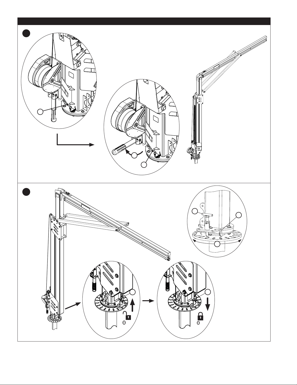
3.2 PLACING THE JIB BOOM: Before the Jib Boom can be used, it must be secured to a Jib Base. See Figure 7 for
reference. To secure the Jib Boom to a Jib Base:
1. Install and prepare the Jib Base (A) per its User Instructions. See Figure 1 for a list of compatible Jib Base models.
2. Secure the Rail Assembly and Gusset to the Upright Assembly using the 1.0 in. hardware provided. Torque hardware
to 130 ft-lb (176 N-m).
3. Connect the Jib Boom to the lifting device (forklift, overhead crane, etc.) that will transport the system. Insert the
Transportation Pin (B) before lifting the Jib Boom. Ensure that the Jib Boom is lifted by the Lifting Ring (A) located
atop the Gusset.
4. Transport the Jib Boom to the Jib Base. Lower the Jib Boom onto the Jib Base (A).
;When transporting the Jib Boom via forklift, driving speed must not exceed 5 mph (8 kpm).
5. After placement of the Jib Boom, rotate the Jib Boom to its desired work position by means of the Rotation Handle.
First, remove the Locking Pin (A) from the Rotation Handle. Then, lift the Rotation Handle to its perpendicular position
(B), and secure the handle by reinserting the Locking Pin (C).
6. To lock rotation of the Jib Boom, position the Locking Pin (A) over one of the holes on the Jib Base and then engage
the Locking Pin to secure the Jib Boom. Alternatively, the Locking Pin may be kept retracted to allow the Jib Boom to
rotate freely. Rotation Stops (B) may be inserted to limit System Rotation (X) within a desired range.
3.3 TRANSPORTING AFTER PLACEMENT: The Jib System may be moved after placement on some Jib Base models. For
more information, see the manufacturer instructions for your Jib Base model.
3.4 ADJUSTING THE HEIGHT OF THE JIB BOOM: After securing the Jib Boom to the Jib Base, you may adjust the
height of the Jib Boom. Height adjustment procedures vary based on your Jib Boom model. See Figure 1 for Jib Boom
identication.
• B1 MODELS: This series of M200 Jib Boom models is adjustable through means of an Adjustment Winch attached to
the base of the Jib Boom. See Figure 8 for reference.
INSTALLING THE ADJUSTMENT WINCH CABLE:
;This series of the M200 Jib Boom is shipped with the cable of the Adjustment Winch already routed through the
M200 Jib Boom. If the cable is already routed, skip to “Using the Adjustment Winch”.
1. Pay out the Cable (B) of the Adjustment Winch (A) by rotating the handle counterclockwise.
2. Extend the cable slowly as you thread it rst through the Upper Pulley (A), then around the Lower Pulley (B) of
the Locking Assembly. From the Lower Pulley, guide the cable back towards the Upper Pulley, then attach the cable
thimble to the 1/2 in. Anchor Bolt (C) between the spacer washers. Torque hardware to 60 ft-lb (81 N-m).
USING THE ADJUSTMENT WINCH:
3. After securing the cable through the system, the System Height (H) of the Jib Boom may be adjusted by turning
the handle of the Adjustment Winch. By turning the handle clockwise (R), the Jib Boom is raised. By turning the
handle counterclockwise (L), the Jib Boom is lowered. The height of the Jib Boom may be set anywhere between
the Side Plates (X) at the top and bottom of the Jib Boom. The Jib Boom may be raised until the Side Plates touch
at the top of the system.
• B2 MODELS: This series of M200 Jib Boom models is adjustable through means of the Adjustment Channel attached
to the Fixed Upright Assembly. See Figure 9 for reference. To adjust the height of the Jib Boom:
1. Remove the two Channel Fasteners (A) from the Adjustment Channel (B).
2. Set the Jib Boom to the desired height. Each hole in the Adjustment Channel adjusts the height of the system by
6.0 in. (15 cm).
3. Fasten the two Channel Fasteners (A) to secure the Adjustment Channel at its new height. Torque 3/4 in. hardware
to 130 ft-lb (176 N-m).
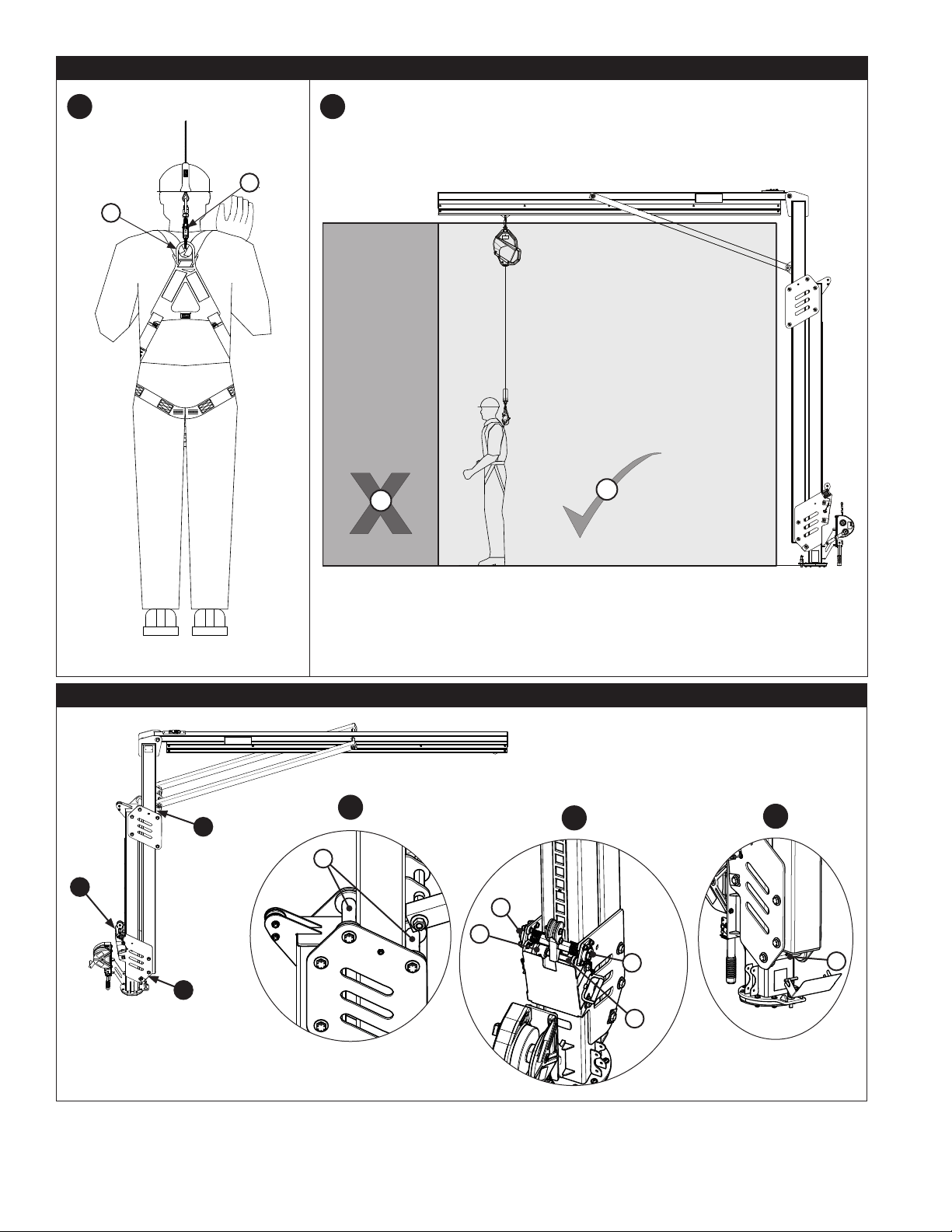
3.5 CONNECTING A SELF-RETRACTING DEVICE (SRD): To connect to the M200 Jib System, the user must rst connect
an SRD to the Jib Boom. See Figure 11 for reference. To connect an SRD to the Jib Boom:
1. Secure the top connector of your SRD (A) to the Connection Eye (B) on the Rail Assembly.
2. Secure the end connector of your SRD (B) to the D-Ring (A) on your Full Body Harness.
3. When using the SRD with the Jib System, stay within the Safe Working Area (A) of the Jib Boom. The user should
remain as directly below the Connection Eye as possible when using the system. For more information on safe work
area, see Section 4.
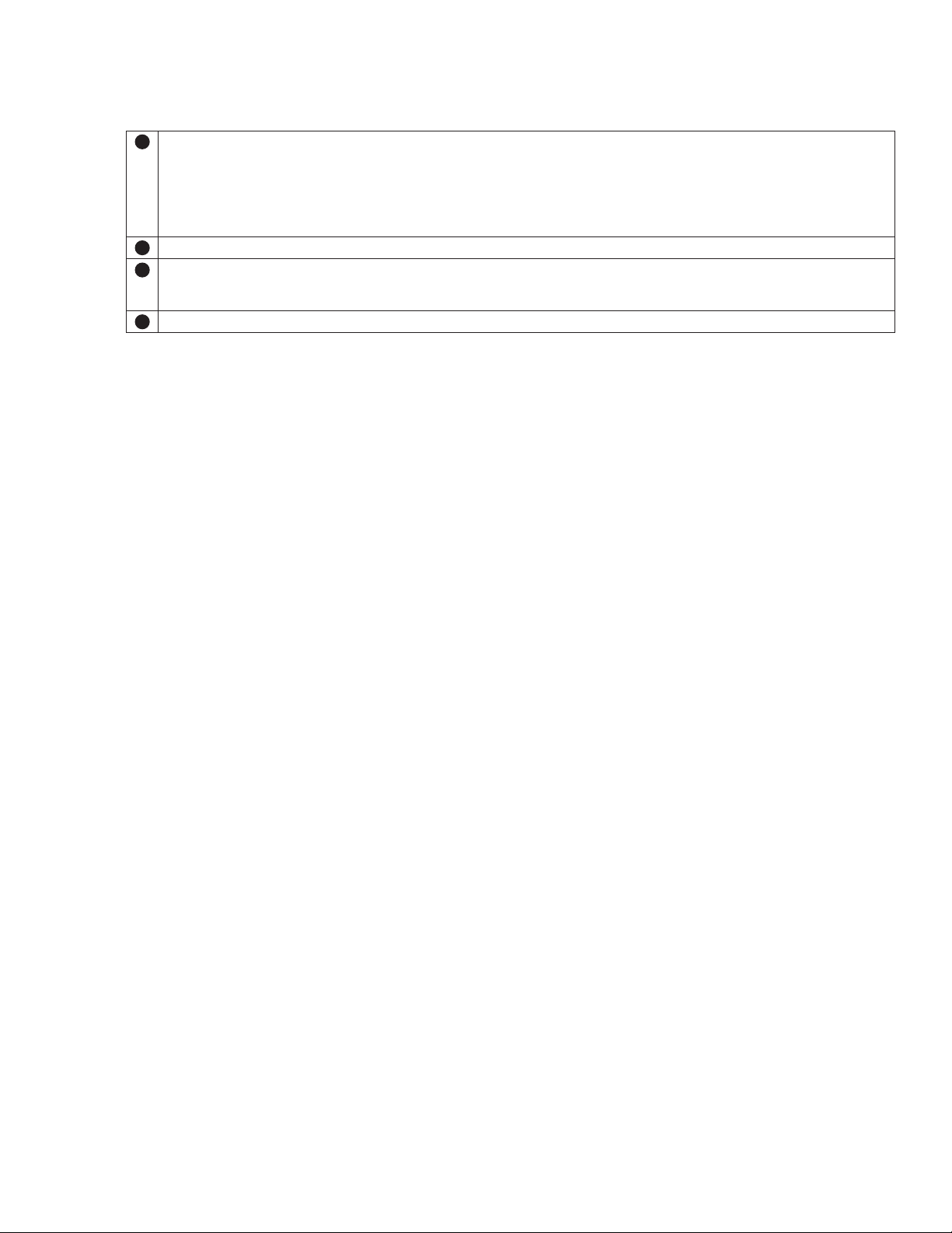
3.6 INSTALLATION AND USE OF THE FORK POCKET KIT (8530912): For B1 Jib Boom models, a Fork Pocket kit (sold
separately) may be secured to the Jib Boom to facilitate easy transport without use of a Jib Base or the D-Ring atop the
Gusset. See Figure 10 for reference. To connect the Fork Pockets to the Jib Boom and transport:
1. Remove the Fasteners (A) from the Steel Plates (B) at the base of the Upright Assembly.
2. Place the Fork Pockets (C) on either side of the Jib Boom, ush against the Steel Plates (B) with their mounting holes
aligned. Insert the new Fasteners (A) to secure, threading through both the Fork Pockets and both the Steel Plates.
Torque 5/8 in. hardware to 75 ft-lb (102 N-m).
3. Verify that the Fork Pockets are securely installed. The Tri-Screws located on the bottom of the forks should be facing
downward.

16
4. To transport, insert the blades of the forklift through the Fork Pockets. Raise the forklift blades to the top of the Fork
Pocket tubes.
;When using the Fork Pockets, always approach from the front of the Jib Boom.
;Use caution when inserting the blades of the forklift through the Fork Pockets. Moving parts may create pinch
points and cause injury.
6. Tighten the Tri-Screws (A) at the base of each Fork Pocket tube to secure each tube to the forklift blades.
7. Verify that the Jib Boom is secured by its Fork Pockets to the forklift. Secure the Fork Pockets to the forklift by
attaching a Chain (A) from each Fork Pocket Connection Ring (B) to the forklift.
4.0 USE
4.1 BEFORE EACH USE: Verify that your work area and Fall Protection system meet all criteria dened in these instructions.
Verify that a formal Rescue Plan is in place. Inspect the system per the ‘User’ inspection points dened in the
“Inspection
and Maintenance Log” (Table 2).
If inspection reveals an unsafe or defective condition, or if there is any doubt about its
condition for safe use, remove the system from service immediately. Clearly tag the system “DO NOT USE”. See Section 5
for more information.
4.2 SAFE WORKING AREA: The Safe Working Area of the Jib Boom does not extend beyond the length of the Jib Boom
itself. See Figure 11.3 for reference. When using the M200 Jib Boom, the user should remain within the indicated Safe
Working Area (A). Leaving the Safe Working Area to an Outside Location (B) is dangerous and could result in serious
injury or death. When working on either side of the M200 Jib System, it is recommended that the user keep the anchor
point as directly overhead as possible. This will minimize the potential for swing falls and any fall distance, in addition to
ensuring the safety of a second user, should the rst user fall.
When two users are attached to the system, it is recommended that rotation of the Jib Boom is locked with the rotation
pin. See Section 3.2. Each user must stay within 30 degrees of either side of the anchor point and never work past the
end of the rail.
5.0 INSPECTION
;After product has been removed from service, it may not be returned to service until a Competent Person conrms in
writing that it is acceptable to do so.
5.1 INSPECTION FREQUENCY: The product shall be inspected before each use by the user and, additionally, by a
Competent Person other than the user at intervals of no longer than one year. A higher frequency of equipment use
and harsher conditions may require increasing the frequency of Competent Person inspections. The frequency of these
inspections should be determined by the Competent Person per the specic conditions of the worksite.
5.2 INSPECTION PROCEDURES: Inspect this product per the procedures listed in the “Inspection and Maintenance Log”.
Documentation of each inspection should be maintained by the owner of this equipment. An inspection and maintenance
log should be placed near the product or be otherwise easily accessible to users. It is recommended that the product is
marked with the date of next or last inspection.
5.3 DEFECTS: If the Jib Boom cannot be returned to service because of an existing defect or unsafe condition, then either
destroy the system or contact 3M or a 3M-authorized service center about possible repair.
5.4 PRODUCT LIFE: The functional life of the Jib Boom is determined by work conditions and maintenance. As long as the
product passes inspection criteria, it may remain in service.
6.0 MAINTENANCE, SERVICE, and STORAGE
6.1 CLEANING: Periodically clean the metal components of the Jib Boom with a soft brush, warm water, and a mild soap
solution. Ensure parts are thoroughly rinsed with clean water.
6.2 SERVICE: Only 3M or parties authorized in writing by 3M may make repairs to this equipment.
6.3 STORAGE: If applicable, store the Jib Boom and associated Fall Protection equipment in a cool, dry, clean environment
out of direct sunlight. Avoid areas where chemical vapors may exist. Thoroughly inspect components after extended
storage.
;Some Jib Base models used with the M200 Jib System are permanent. The Jib Boom may be removed from these
Jib Bases for storage or transport, but the Jib Base will have to remain.
17
7.0 LABELS and MARKINGS
7.1 LABELS: Figures 13 and 14 illustrate labels present on the Jib Boom. Figure 13 illustrates label locations and Figure
14 displays those associated labels. Labels must be replaced if they are not present or are not fully legible. Information
provided on each label is as follows:
AThe label present on Location A varies based upon whether your system allows one or two simultaneous users.
Label 9515103 - 1 user
Label 9515112 - 2 users
A) 3M Logo B) Applicable Standards C) Read all instructions.
D) Jib Boom Model Numbers and Weight Values E) Maximum Arresting Force 1,350 lbf (6 kN)
F) Capacity - Each user must have a combined weight (clothing, tools, etc.) of no more than 310 lb. (140 kg).
BA) Manufactured (Year/Month) B) Model Number C) Serial Number
CA) Engage the Locking Pin to prevent rotation of the system.
B) Disengage the Locking Pin to enable full rotation of the system.
C) Maximum System Rotation is equivalent to the limits allowed by engagement or disengagement of the pin.
DA) 3M Logo
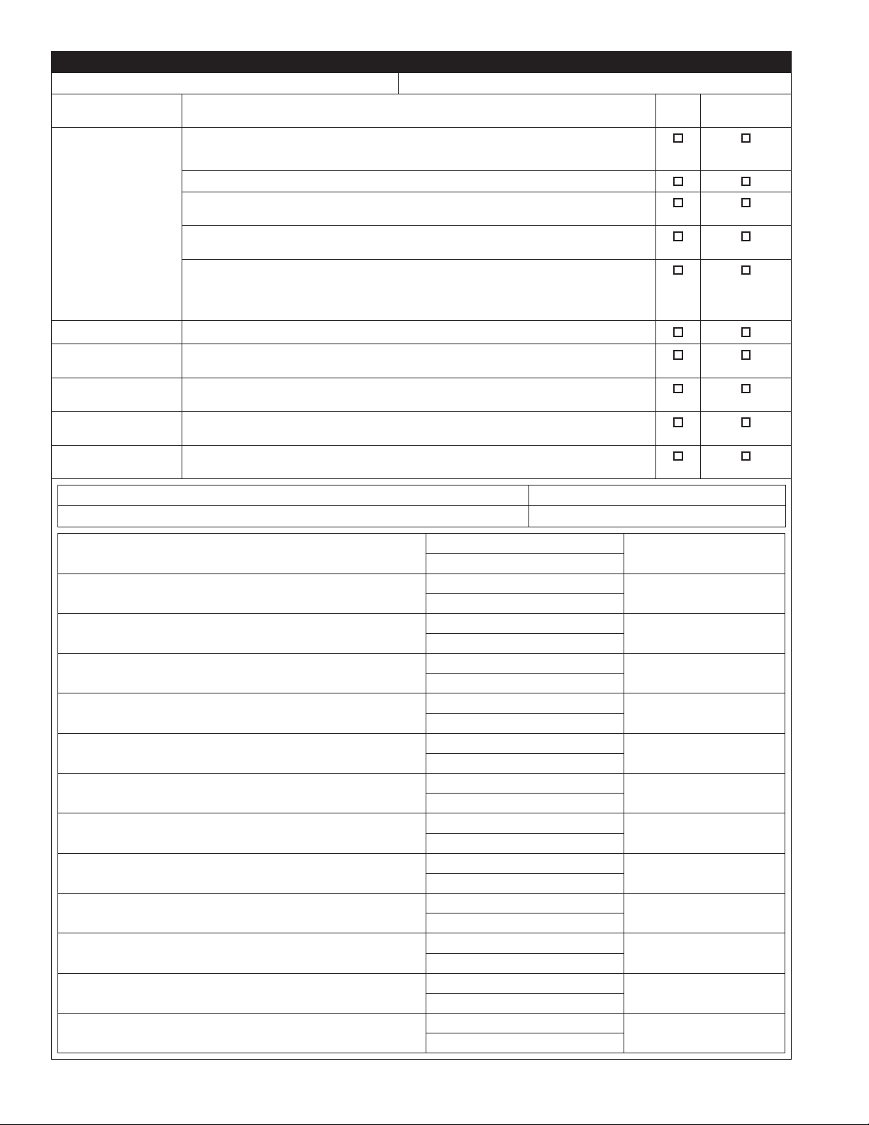
Table 2 – Inspection and Maintenance Log
Inspection Date: Inspected By:
Components: Inspection: (See Section 1 for Inspection Frequency)User Competent
Person
Jib Boom
(Figure 2)
Inspect the entire system for damage, deformation, corrosion, and rust. Look
for cracks, bends, dents, or wear that could aect strength and operation of the
system.
Inspect all fasteners for damage or corrosion. Tighten as necessary.
Inspect all moving parts for chips, cracks, breaks, or worn areas that can cause
malfunction during operation.
Verify that all adjustment points (pins, bolts, tri-screws, adjusting screws, etc.)
are in full functional condition and are adjusted properly.
Fully lower the Jib Boom to take tension o the cable. Verify that the springs in
the Lower Pulley (I) are functional and free of rust or other obstructions. Verify
that the cable of the Adjustment Winch (G) has no frays or tearing. Ensure the
locking assembly engages.
Winch Assembly Inspect the Winch Assembly per 3M instruction manual 8511324.
Rollers and Bearings
(Figure 12) Grease the Rollers (A) and Bearings (B) of the Adjustable Upright Assembly for
B1 Jib Boom models. Ensure that all Roller locations are greased.
Anchor Connection
Points Ensure Anchor Connection Points are free of corrosion, cracks, or other
imperfections that my cause malfunction during operation.
Labels
(Figures 13 and 14) Verify that all labels are present and fully legible.
Fall Protection
System Additional Fall Protection equipment (winches, SRDs, etc.) that are used with
the system should be inspected per the manufacturer instructions.
Serial Number(s): Date Purchased:
Model Number: Date of First Use:
Corrective Action/Maintenance: Approved By: Next inspection due:
Date:
Corrective Action/Maintenance: Approved By: Next inspection due:
Date:
Corrective Action/Maintenance: Approved By: Next inspection due:
Date:
Corrective Action/Maintenance: Approved By: Next inspection due:
Date:
Corrective Action/Maintenance: Approved By: Next inspection due:
Date:
Corrective Action/Maintenance: Approved By: Next inspection due:
Date:
Corrective Action/Maintenance: Approved By: Next inspection due:
Date:
Corrective Action/Maintenance: Approved By: Next inspection due:
Date:
Corrective Action/Maintenance: Approved By: Next inspection due:
Date:
Corrective Action/Maintenance: Approved By: Next inspection due:
Date:
Corrective Action/Maintenance: Approved By: Next inspection due:
Date:
Corrective Action/Maintenance: Approved By: Next inspection due:
Date:
Corrective Action/Maintenance: Approved By: Next inspection due:
Date:

GLOBAL PRODUCT WARRANTY, LIMITED REMEDY
AND LIMITATION OF LIABILITY
WARRANTY: THE FOLLOWING IS MADE IN LIEU OF ALL WARRANTIES OR CONDITIONS, EXPRESS
OR IMPLIED, INCLUDING THE IMPLIED WARRANTIES OR CONDITIONS OF MERCHANTABILITY OR
FITNESS FOR A PARTICULAR PURPOSE.
Unless otherwise provided by local laws, 3M fall protection products are warranted against factory
defects in workmanship and materials for a period of one year from the date of installation or fi rst use
by the original owner.
LIMITED REMEDY: Upon written notice to 3M, 3M will repair or replace any product determined by
3M to have a factory defect in workmanship or materials. 3M reserves the right to require product be
returned to its facility for evaluation of warranty claims. This warranty does not cover product damage
due to wear, abuse, misuse, damage in transit, failure to maintain the product or other damage beyond
3M’s control. 3M will be the sole judge of product condition and warranty options.
This warranty applies only to the original purchaser and is the only warranty applicable to 3M’s fall
protection products. Please contact 3M’s customer service department in your region for assistance.
LIMITATION OF LIABILITY: TO THE EXTENT PERMITTED BY LOCAL LAWS, 3M IS NOT LIABLE
FOR ANY INDIRECT, INCIDENTAL, SPECIAL OR CONSEQUENTIAL DAMAGES INCLUDING, BUT NOT
LIMITED TO LOSS OF PROFITS, IN ANY WAY RELATED TO THE PRODUCTS REGARDLESS OF THE
LEGAL THEORY ASSERTED.
GLOBAL PRODUKTGARANTI, BEGRÆNSEDE RETSMIDLER
OG BEGRÆNSNING AF GARANTIFORPLIGTELSER
GARANTI: FØLGENDE ERSTATTER ALLE GARANTIER ELLER BETINGELSER, UDTRYKKELIGE ELLER
UNDERFORSTÅEDE, HERUNDER DE UNDERFORSTÅEDE GARANTIER ELLER BETINGELSER FOR
SALGBARHED ELLER EGNETHED TIL ET SPECIFIKT FORMÅL.
Bortset fra hvad der sikres ved gældende love, er 3M’s produkter til faldsikring omfattet af en garanti
mod fabriksdefekter i den håndværksmæssige udførelse og materialer i en periode på et år fra
installationsdatoen eller den første ejers ibrugtagningsdato.
BEGRÆNSEDE RETSMIDLER: Ved skriftlig henvendelse til 3M vil 3M reparere eller erstatte ethvert
produkt, der af 3M vurderes at have en fabriksdefekt i den håndværksmæssige udførelse eller
materialer. 3M forbeholder sig ret til at kræve produktet returneret til dets anlæg for at vurdere krav
om garanti. Denne garanti dækker ikke skade på produktet slid, misbrug, forkert brug, transportskade,
manglende vedligeholdelse af produktet eller anden skade uden for 3M’s kontrol. 3M vil alene fastslå
produktets tilstand og mulighederne for garanti.
Denne garanti gælder kun for den oprindelige køber og er den eneste garanti gældende for 3M’s
produkter til faldsikring. Kontakt venligst 3M’s kundeserviceafdeling i dit område for at få hjælp.
BEGRÆNSNING AF GARANTIFORPLIGTELSER: I DEN UDSTRÆKNING DET TILLADES AF LOKALE
LOVE ER 3M IKKE ANSVARLIG FOR NOGEN INDIREKTE, TILFÆLDIGE, SPECIELLE ELLER PÅFØLGENDE
SKADER, HERUNDER MEN IKKE BEGRÆNSET TIL TAB AF FORTJENESTE, DER PÅ NOGEN MÅDE ER
RELATERET TIL PRODUKTERNE UANSET DEN UDLAGTE JURIDISKE TEORI.
GLOBALE PRODUKTGARANTIE, BESCHRÄNKTES RECHTSMITTEL
UND HAFTUNGSBESCHRÄNKUNG
GARANTIE: FOLGENDES GILT STELLVERTRETEND FÜR ALLE GARANTIEN ODER BEDINGUNGEN,
EINSCHLIESSLICH STILLSCHWEIGEND ANGENOMMENER GARANTIEN ODER BEDINGUNGEN
HINSICHTLICH DER TAUGLICHKEIT ODER EIGNUNG FÜR EINEN BESTIMMTEN ZWECK.
Soweit gesetzlich nicht anders vorgeschrieben, werden bei 3M-Produkten für die Absturzsicherung
werksseitige Mängel bei Verarbeitung und Material für einen Zeitraum von einem Jahr ab dem Datum
der Installation oder der erstmaligen Benutzung durch den ursprünglichen Eigentümer garantiert.
BESCHRÄNKTES RECHTSMITTEL: Nach schriftlicher Mitteilung an 3M wird 3M jedes Produkt ersetzen
oder austauschen, bei dem durch 3M ein werkseitiger Material- oder Verarbeitungsfehler festgestellt
wird. 3M behält sich das Recht vor, die Rücksendung des Produkts an das Werk zur Beurteilung der
Garantieansprüche zu verlangen. Unter dieser Garantie sind keine Schäden am Produkt gedeckt, die auf
Verschleiß, Missbrauch, Transportschäden, Versäumnis der Instandhaltung des Produkts oder sonstige
außerhalb der Kontrolle von 3M liegende Schäden zurückzuführen sind. 3M triff t allein die Entscheidung
über Produktzustand und Garantieoptionen.
Diese Garantie gilt ausschließlich für den ursprünglichen Käufer und ist die einzige, die für
Absturzsicherungsprodukte von 3M maßgeblich ist. Kontaktieren Sie bitte die Kunden-Service-Abteilung,
um Unterstützung zu erhalten.
HAFTUNGSBESCHRÄNKUNG: SOWEIT NACH GELTENDEM RECHT ZULÄSSIG, IST 3M NICHT
HAFTBAR FÜR UNMITTELBARE, MITTELBARE, BESONDERE SCHÄDEN ODER FOLGESCHÄDEN JEDER
ART, EINSCHLIESSLICH VON VERLUST VON GEWINN, DER IM ZUSAMMENHANG MIT DEN PRODUKTEN
ENTSTEHT, UNGEACHTET DER ANGEFÜHRTEN RECHTSTHEORIE.
GARANTÍA GLOBAL DE PRODUCTO, COMPENSACIÓN LIMITADA
Y LIMITACIÓN DE RESPONSABILIDAD
GARANTÍA: LAS SIGUIENTES DISPOSICIONES PREVALECERÁN SOBRE CUALQUIER GARANTÍA O
CONDICIÓN, EXPRESA O IMPLÍCITA, INCLUIDAS LAS CONDICIONES O GARANTÍAS IMPLÍCITAS DE
COMERCIABILIDAD O IDONEIDAD PARA UN FIN ESPECÍFICO.
Salvo que la legislación local estipule lo contrario, los productos de protección contra caídas de 3M están
garantizados contra defectos de fabricación de mano de obra y materiales durante un periodo de un año
a partir de la fecha de instalación o del primer uso por parte del propietario original.
COMPENSACIÓN LIMITADA: Tras recibir comunicación por escrito, 3M reparará o sustituirá los
productos que considere que tienen un defecto de fabricación de mano de obra o materiales. 3M se reserva
el derecho a solicitar la devolución del producto a sus instalaciones para evaluar las reclamaciones de
garantía. Esta garantía no cubre los daños en el producto resultantes de desgaste, mal uso, uso indebido,
daños durante el tránsito, mantenimiento inapropiado del producto o daños que escapen al control de
3M. 3M será el único con derecho a determinar el estado del producto y las opciones de garantía.
Esta garantía puede ser utilizada únicamente por el comprador original y es la única que cubre
los productos de protección contra caídas de 3M. Si necesita ayuda, póngase en contacto con el
departamento de servicios de atención al cliente de 3M.
LIMITACIÓN DE RESPONSABILIDAD: EN LA MEDIDA QUE LO PERMITA LA LEGISLACIÓN LOCAL,
3M NO SE RESPONSABILIZARÁ DE LOS DAÑOS INDIRECTOS, FORTUITOS, ESPECIALES O
RESULTANTES, INCLUIDA LA PÉRDIDA DE GANANCIA, RELACIONADOS DE MANERA ALGUNA CON
LOS PRODUCTOS, INDEPENDIENTEMENTE DE LOS FUNDAMENTOS LEGALES QUE SE ALEGUEN.
GLOBAALI TUOTETAKUU, RAJATTU KORVAUS
JA VASTUUNRAJOITUS
TAKUU: SEURAAVA ON LAADITTU KAIKKIEN SUORIEN TAI EPÄSUORIEN TAKUIDEN TAI EHTOJEN
SIJAAN, MUKAAN LUKIEN EPÄSUORAT TAKUUT MYYNTIKELPOISUUDESTA TAI SOPIVUUDESTA TIETTYYN
TARKOITUKSEEN.
Ellei muutoin paikallisissa laeissa säädetä, 3M-putoamisenestotuotteilla on yhden vuoden takuu
valmistusvirheitä ja materiaalivirheitä koskien asennuspäivästä tai alkuperäisen käyttäjän
ensimmäisestä käyttöpäivästä alkaen.
RAJATTU KORVAUS: Kirjallisella 3M:lle lähetetyllä ilmoituksella 3M korjaa tai vaihtaa kaikki tuotteet,
joissa on 3M:n määrittelemä valmistus- tai materiaalivirhe. 3M pidättää oikeuden vaatia tuotetta
palautettavaksi tehtaalle takuuvaatimusten arvioimiseksi. Tämä takuu ei kata kulumisesta, tuotteen
väärinkäytöstä, kuljetusvahingoista tai tuotteen epäonnistuneesta huollosta aiheutunutta vauriota tai
muuta vauriota, johon 3M ei pysty vaikuttamaan. Tuotteen kunnosta ja takuuvaihtoehdoista päätöksen
tekee ainoastaan 3M.
Tämä takuu koskee vain alkuperäistä ostajaa, ja sitä sovelletaan ainoastaan 3M:n putoamisenestotuotteisiin.
Ota yhteyttä paikalliseen 3M:n asiakaspalveluun saadaksesi apua.
VASTUUNRAJOITUS: PAIKALLISTEN LAKIEN SALLIMISSA MÄÄRIN 3M EI OLE VASTUUSSA MISTÄÄN
EPÄSUORASTA, SATTUMANVARAISESTA, ERITYISESTÄ TAI AIHEUTUNEESTA VAHINGOSTA, MUKAAN
LUKIEN, MUTTA SIIHEN KUITENKAAN RAJOITTUMATTA, TUOTTOJEN MENETTÄMINEN, MILLÄÄN TAVALLA
TUOTTEISIIN LIITTYEN OIKEUSTEORIASTA HUOLIMATTA.
GARANTIE PRODUIT INTERNATIONALE, RECOURS LIMITÉ
ET LIMITATION DE LA RESPONSABILITÉ
GARANTIE : LES DISPOSITIONS SUIVANTES SONT PRISES EN LIEU ET PLACE DE TOUTES LES GARANTIES
OU CONDITIONS, EXPRESSES OU IMPLICITES, Y COMPRIS LES GARANTIES OU CONDITIONS IMPLICITES
DE QUALITÉ MARCHANDE OU D'ADAPTATION À UN USAGE SPÉCIFIQUE.
À moins d’un confl it avec une législation locale, les produits antichute de 3M sont garantis contre les défauts
de fabrication en usine et de matériaux pendant une période d'un an à compter de la date d'installation ou
de la première utilisation par le propriétaire initial.
RECOURS LIMITÉ : Sur demande écrite à 3M, 3M s’engage à réparer ou remplacer tout produit considéré
par 3M comme souff rant d’un défaut de fabrication en usine ou de matériaux. 3M se réserve le droit d’exiger
que le produit lui soit retourné pour une évaluation de la réclamation au titre de la garantie. Cette garantie
ne couvre pas les dommages du produit liés à l’usure, aux abus, à la mauvaise utilisation, aux dommages
liés aux transports, au manque d’entretien du produit ou tout autre dommage indépendant du contrôle
de 3M. 3M sera l’unique juge de la condition du produit et des options de la garantie.
Cette garantie ne s’applique qu’au propriétaire initial et elle constitue l’unique garantie s’appliquant aux
produits antichute de 3M. Veuillez contacter le service à la clientèle 3M de votre région pour obtenir de
l’assistance.
LIMITATION DE LA RESPONSABILITÉ : DANS LES MESURES PERMISES PAR LA LÉGISLATION
LOCALE, 3M N’EST PAS RESPONSABLE POUR TOUT DOMMAGE INDIRECT, ACCESSOIRE, SPÉCIFIQUE OU
CONSÉCUTIF, Y COMPRIS, MAIS SANS S'Y LIMITER, LA PERTE DE PROFITS, LIÉE DE QUELQUE MANIÈRE
QUE CE SOIT AUX PRODUITS, MALGRÉ LA THÉORIE JURIDIQUE REVENDIQUÉE.
GARANZIA GLOBALE SUL PRODOTTO, RIMEDIO LIMITATO
E LIMITAZIONE DI RESPONSABILITÀ
GARANZIA: LA SEGUENTE GARANZIA SOSTITUISCE TUTTE LE GARANZIE O CONDIZIONI, ESPRESSE O
IMPLICITE, COMPRESE LE GARANZIE O CONDIZIONI IMPLICITE DI COMMERCIABILITÀ O IDONEITÀ PER
UN PARTICOLARE SCOPO.
Salvo ove diversamente specifi cato dalle leggi locali, i prodotti di protezione anticaduta 3M sono
garantiti da difetti di fabbricazione e dei materiali per un periodo di un anno dalla data di installazione o
di primo utilizzo da parte del proprietario originale.
RIMEDIO LIMITATO: previa comunicazione scritta a 3M, 3M riparerà o sostituirà qualsiasi prodotto
in cui 3M avrà individuato un difetto di fabbricazione o dei materiali. 3M si riserva il diritto di richiedere
la restituzione del prodotto all'impianto per la valutazione della richiesta di risarcimento in garanzia.
La presente garanzia non copre i danni al prodotto causati da usura, abuso, utilizzo errato, trasporto
o mancata manutenzione del prodotto o altri danni avvenuti fuori dal controllo di 3M. 3M è la sola che
potrà giudicare le condizioni del prodotto e le opzioni di garanzia.
La presente garanzia è valida solo per l’acquirente originale ed è l’unica applicabile ai prodotti di
protezione anticaduta 3M. Per assistenza, contattare il Servizio Clienti di 3M della propria area.
LIMITAZIONE DI RESPONSABILITÀ: NELLA MISURA CONSENTITA DALLE LEGGI LOCALI, 3M NON
RISPONDE DI EVENTUALI DANNI INDIRETTI, INCIDENTALI, SPECIALI O CONSEQUENZIALI COMPRESI,
SENZA LIMITAZIONE, DANNI PER PERDITA DI PROFITTO, IN QUALSIASI MODO COLLEGATI AI
PRODOTTI INDIPENDENTEMENTE DALLA TEORIA LEGALE ASSERITA.
WERELDWIJDE PRODUCTGARANTIE, BEPERKTE VERHAALSMOGELIJKHEID
EN BEPERKING VAN AANSPRAKELIJKHEID
GARANTIE: DE VOLGENDE BEPALING VERVANGT ALLE GARANTIES OF VOORWAARDEN, EXPLICIET
OF IMPLICIET, INCLUSIEF DE IMPLICIETE GARANTIES OF VOORWAARDEN VAN VERKOOPBAARHEID OF
GESCHIKTHEID VOOR EEN BEPAALD DOEL.
Tenzij anders is bepaald door lokale wetgeving, zijn valbeschermingsproducten van 3M voorzien van een
garantie op fabrieksfouten door fabricage- en materiaalgebreken gedurende een periode van één jaar
na de datum van installatie of het eerste gebruik door de oorspronkelijke eigenaar.
BEPERKTE VERHAALSMOGELIJKHEID: Na schriftelijke kennisgeving aan 3M zal 3M eender welk
product repareren of vervangen waarvan 3M heeft vastgesteld dat het een fabrieksfout heeft door
een fabricage- of materiaalgebrek. 3M behoudt zich het recht voor om te eisen dat het product naar
zijn vestiging wordt geretourneerd om garantieaanspraken te beoordelen. Deze garantie is niet van
toepassing op productschade door slijtage, oneigenlijk gebruik, misbruik, transportschade, nalatigheid
bij onderhoud van het product of andere schade waarover 3M geen controle heeft. 3M zal als enige
oordelen over de toestand van het product en garantieopties.
Deze garantie is alleen van toepassing op de oorspronkelijke koper en is de enige garantie die van
toepassing is op valbeschermingsproducten van 3M. Neem contact op met de klantendienst van 3M voor
uw regio als u assistentie wenst.
BEPERKING VAN AANSPRAKELIJKHEID: VOOR ZOVER TOEGESTAAN DOOR LOKALE WETGEVING,
IS 3M NIET AANSPRAKELIJK VOOR ENIGE INDIRECTE, INCIDENTELE, SPECIALE OF GEVOLGSCHADE,
INCLUSIEF, MAAR NIET BEPERKT TOT, WINSTVERLIES, DIE OP ENIGE WIJZE VERBAND HOUDT MET DE
PRODUCTEN, ONGEACHT DE RECHTSLEER DIE WORDT AANGEHAALD.
GLOBAL PRODUKTGARANTI, BEGRENSET AVHJELP
OG BEGRENSNING AV ERSTATNINGSANSVAR
GARANTI: DET FØLGENDE KOMMER I STEDET FOR ALLE GARANTIER ELLER VILKÅR, UTTRYKKELIGE
ELLER UNDERFORSTÅTTE, INKLUDERT DE UNDERFORSTÅTTE GARANTIENE ELLER VILKÅRENE OM
SALGBARHET ELLER EGNETHET FOR ET BESTEMT FORMÅL.
Med mindre annet er bestemt av lokale lover, er 3Ms fallsikringsprodukter garantert mot fabrikasjonsfeil
i håndverksmessig utførelse og materialer for en periode på ett år fra installasjonsdatoen eller første
bruk av den opprinnelige eieren.
BEGRENSET AVHJELP: Ved skriftlig melding til 3M, vil 3M reparere eller erstatte ethvert produkt som
av 3M fastslås å ha en fabrikasjonsfeil i håndverksmessig utførelse eller materialer. 3M forbeholder
seg retten til å kreve at produktet blir levert tilbake til fabrikken for evaluering av garantikrav. Denne
garantien dekker ikke produktskade grunnet slitasje, misbruk, skade i transitt, unnlatelse av å
vedlikeholde produktet eller annen skade utenfor 3Ms kontroll. 3M vil være den eneste til å bedømme
produktvilkår og garantialternativer.
Denne garantien gjelder kun den opprinnelige kjøperen og er den eneste garantien som er anvendelig
for 3Ms fallsikringsprodukter. Vennligst kontakt 3Ms kundeserviceavdeling i ditt område for hjelp.
BEGRENSNING AV ERSTATNINGSANSVAR: I DEN UTSTREKNING DET ER TILLATT AV LOKALE
LOVER, ER IKKE 3M ERSTATNINGSANSVARLIG FOR NOEN SOM HELST INDIREKTE, HENDELIGE,
SPESIELLE ELLER FØLGEMESSIGE SKADER INKLUDERT, MEN IKKE BEGRENSET TIL TAP AV
FORTJENESTE, PÅ NOEN SOM HELST MÅTE FORBUNDET MED PRODUKTENE, UAVHENGIG AV HVILKEN
JURIDISK TEORI SOM PÅBEROPES.
GLOBAL PRODUKTGARANTI, BEGRÄNSAD KOMPENSATION
OCH BEGRÄNSAD ANSVARSSKYLDIGHET
GARANTI: FÖLJANDE GÄLLER SOM ERSÄTTNING FÖR ALLA GARANTIER ELLER VILLKOR, UTTRYCKLIGA
ELLER UNDERFÖRSTÅDDA, INKLUSIVE UNDERFÖRSTÅDDA GARANTIER ELLER VILLKOR FÖR
SÄLJBARHET ELLER LÄMPLIGHET FÖR ETT VISST ÄNDAMÅL.
Såvida inte annat stipuleras i lokala lagar, garanteras 3M:s fallskyddsprodukter mot fabrikationsfel
avseende tillverkning och material under en period av ett år från datum för ursprunglig ägares
installation eller första användning.
BEGRÄNSAD KOMPENSATION: Efter skriftlig avisering till 3M, kommer 3M att reparera eller byta
ut varje produkt, som av 3M fastställts vara behäftad med fabrikationsfel vad gäller tillverkning eller
material. 3M förbehåller sig rätten att kräva att produkt returneras till företagets anläggning för
utvärdering av garantianspråk. Denna garanti omfattar inte produktskada till följd av slitage, felaktig
användning, missbruk, skada under transport, underlåtenhet att sköta produkten eller annan skada
utom 3M:s kontroll. 3M är ensam bedömare av produktskick och garantialternativ.
Denna garanti avser enbart den ursprunglige köparen och är den enda garanti som gäller för
3M:s fallskyddsprodukter. Kontakta 3M:s kundtjänstavdelning i din region för assistans.
BEGRÄNSNING AV ANSVARSSKYLDIGHET: I DEN OMFATTNING SOM TILLÅTS AV LOKALA LAGAR,
ANSVARAR 3M INTE FÖR NÅGRA INDIREKTA, OFÖRUTSEDDA, SPECIELLA ELLER FÖLJDSKADOR,
INKLUSIVE MEN INTE BEGRÄNSAT TILL FÖRLUST AV VINSTER, VILKA PÅ NÅGOT SÄTT HÄNFÖRTS TILL
PRODUKTERNA, OAVSETT HÄVDAD RÄTTSLIG GRUND.

USA
3833 SALA Way
Red Wing, MN 55066-5005
Distributed by Engineered Fall Protection
www.EngineeredFallProtection.com
Tel: (314) 492-4422
ISO
9001
FM534873
EU DECLARATION OF CONFORMITY:
3M
Table of contents
Other DBI SALA Protection Device manuals

Popular Protection Device manuals by other brands


nxt
nxt BIA-nXt-DPC 1-22 Installation and operation manual

TFortis
TFortis SG-Switch operating manual

BERNINI DESIGN
BERNINI DESIGN Be172 instruction manual

Rayleigh Instruments
Rayleigh Instruments RI-ENERGYSET-3P-ESS-50-100 manual

E.K.T.
E.K.T. ke-DP01 quick start guide

Sola HD
Sola HD STV100K Series instruction manual


