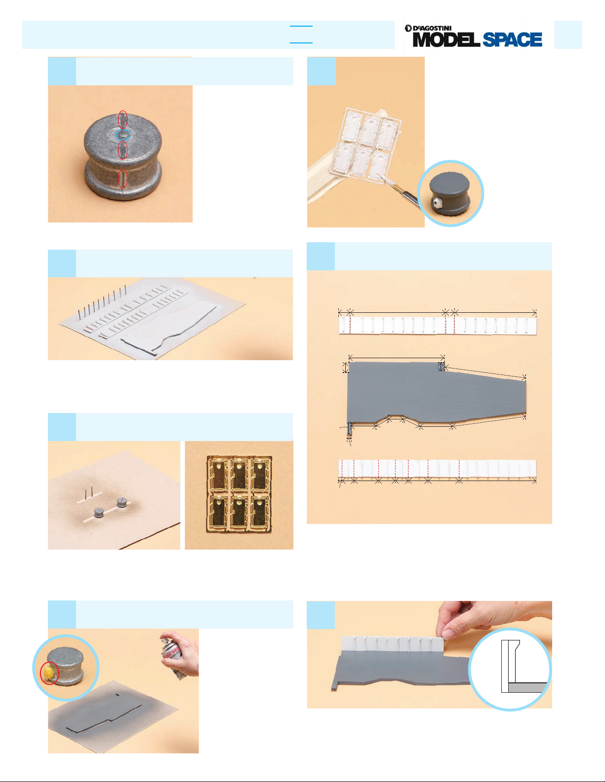
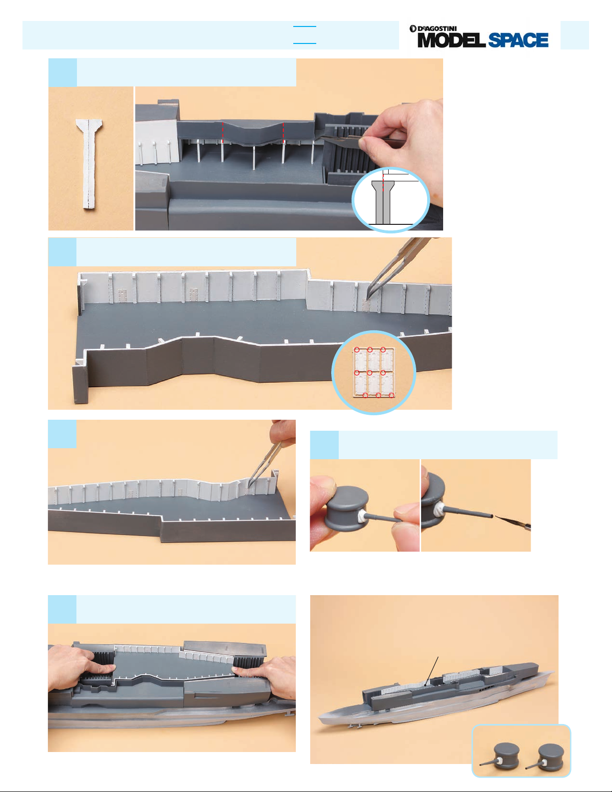
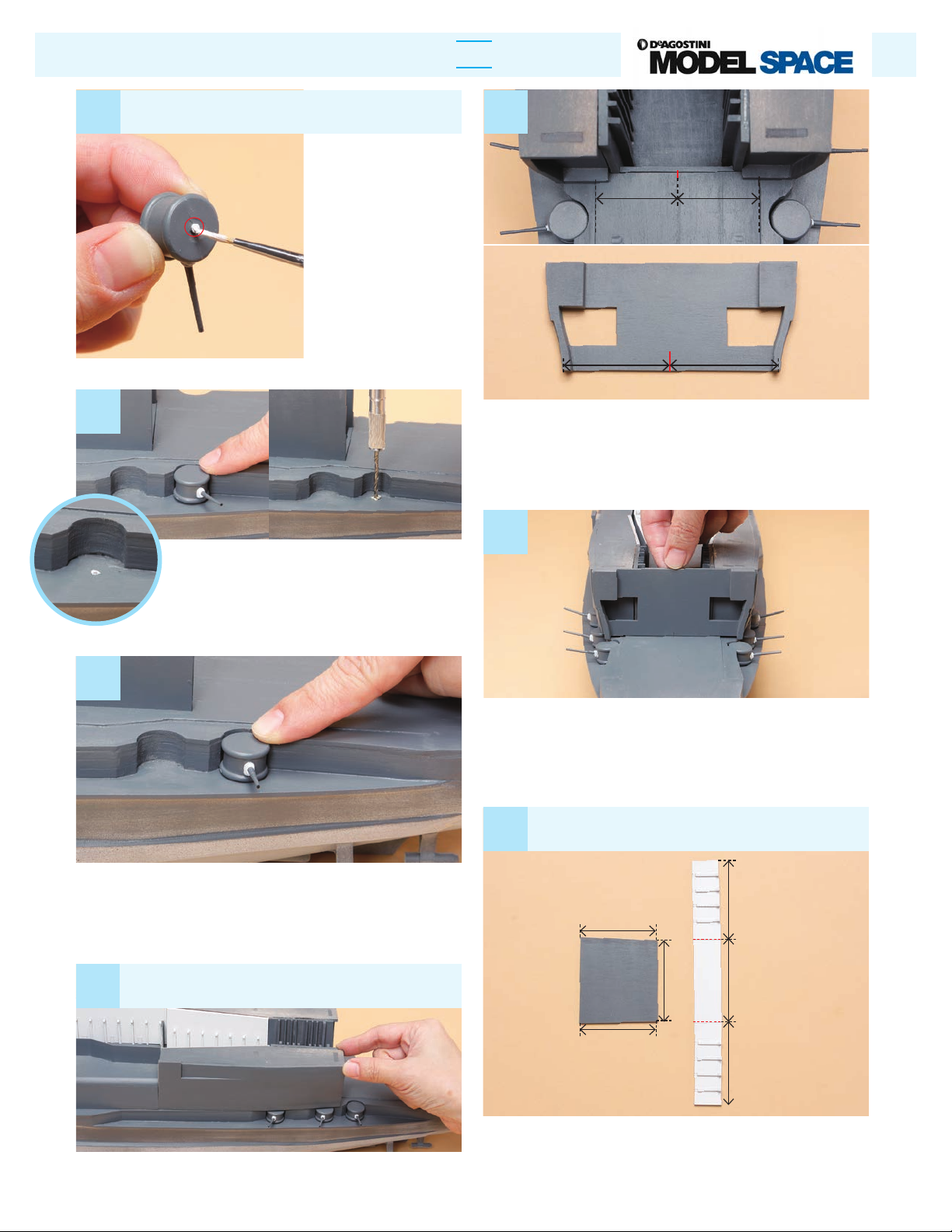
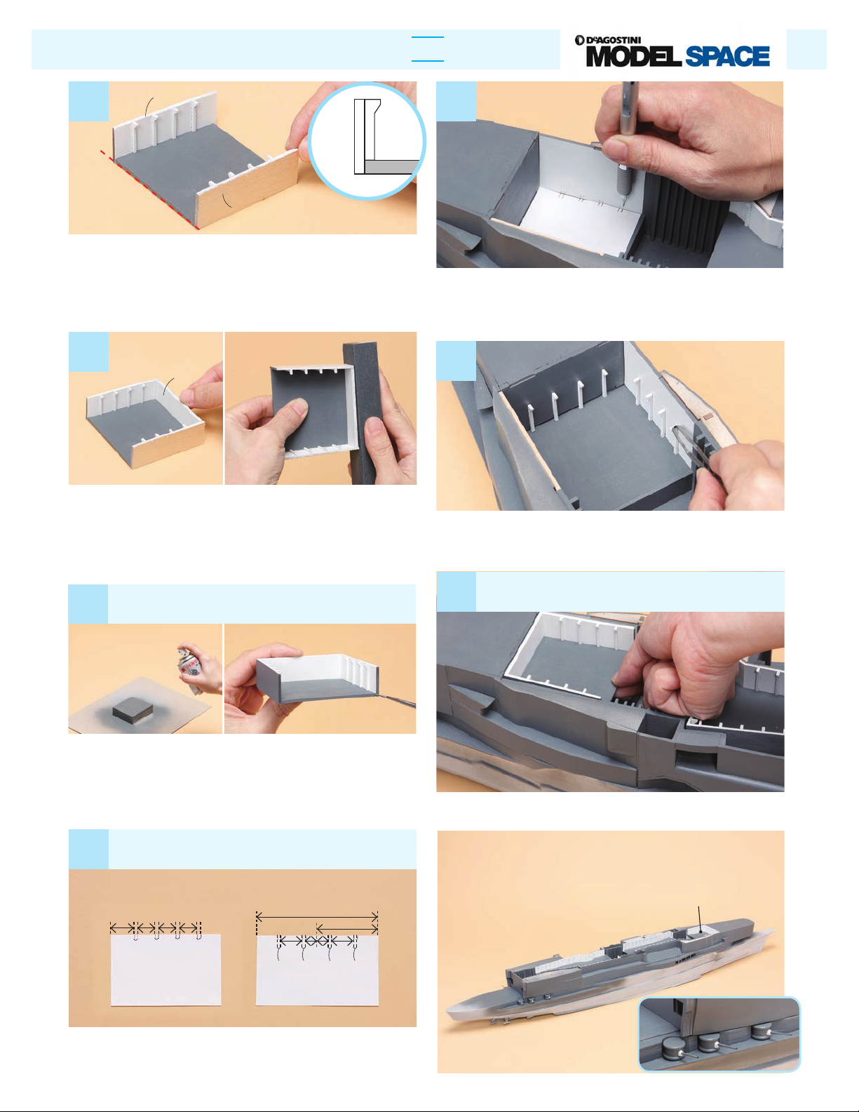
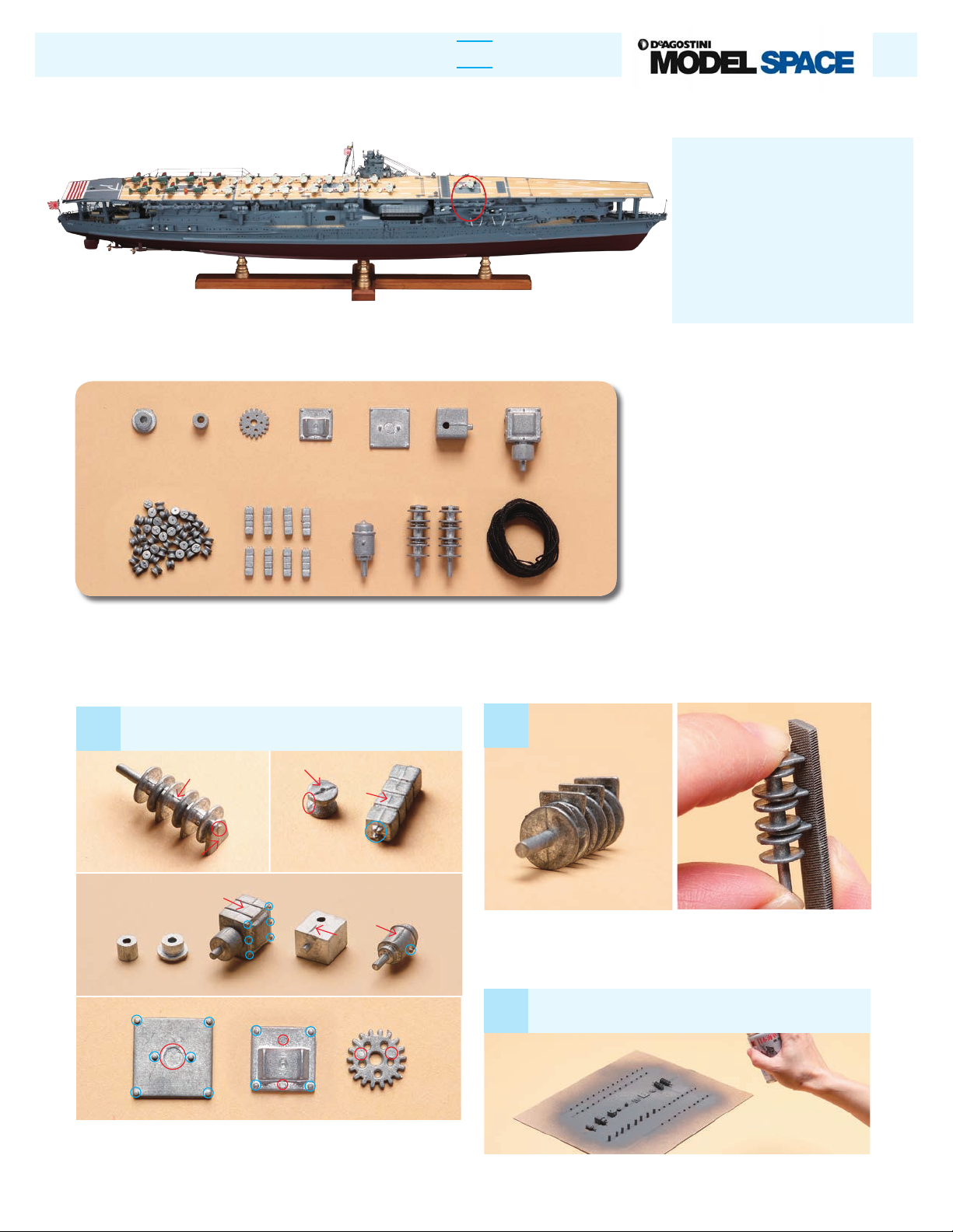
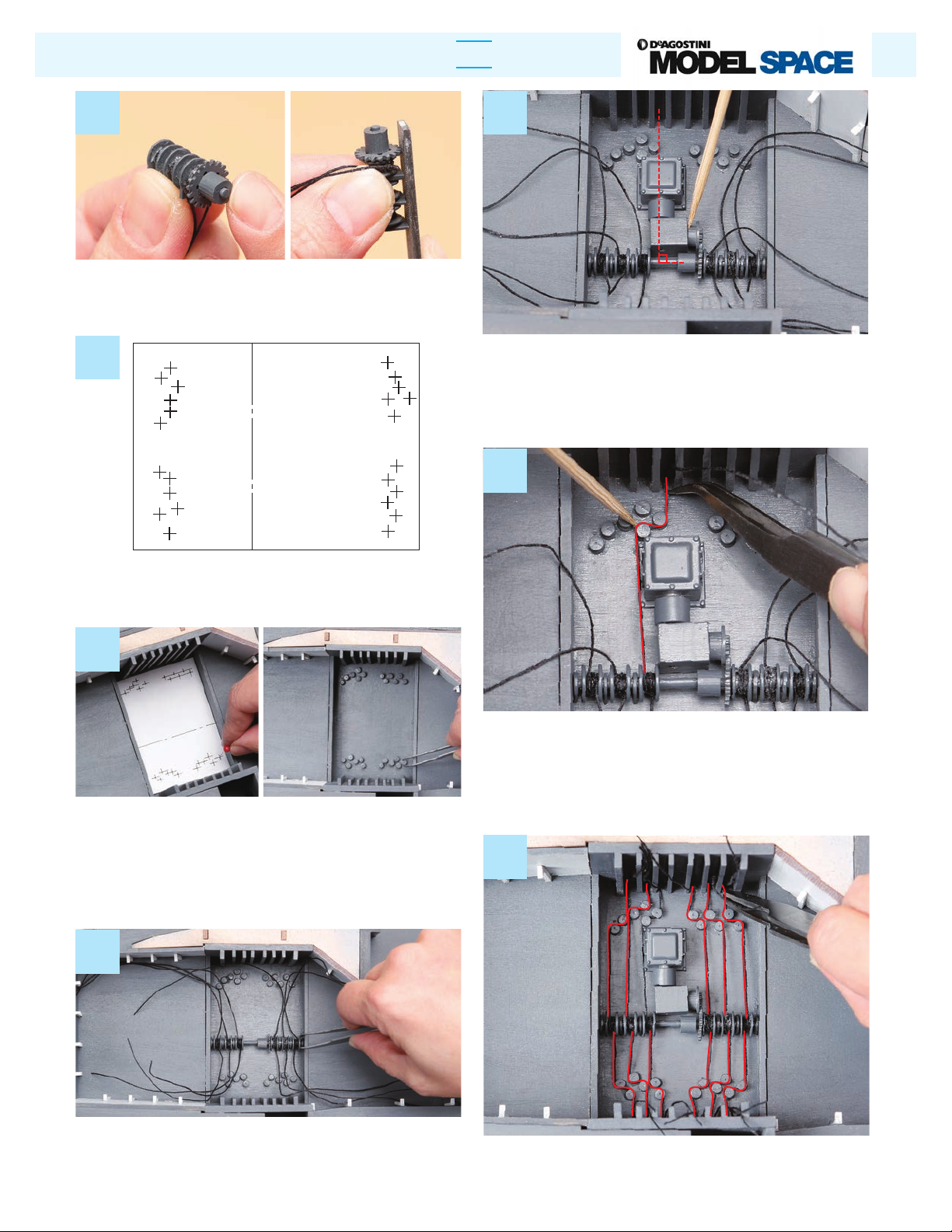
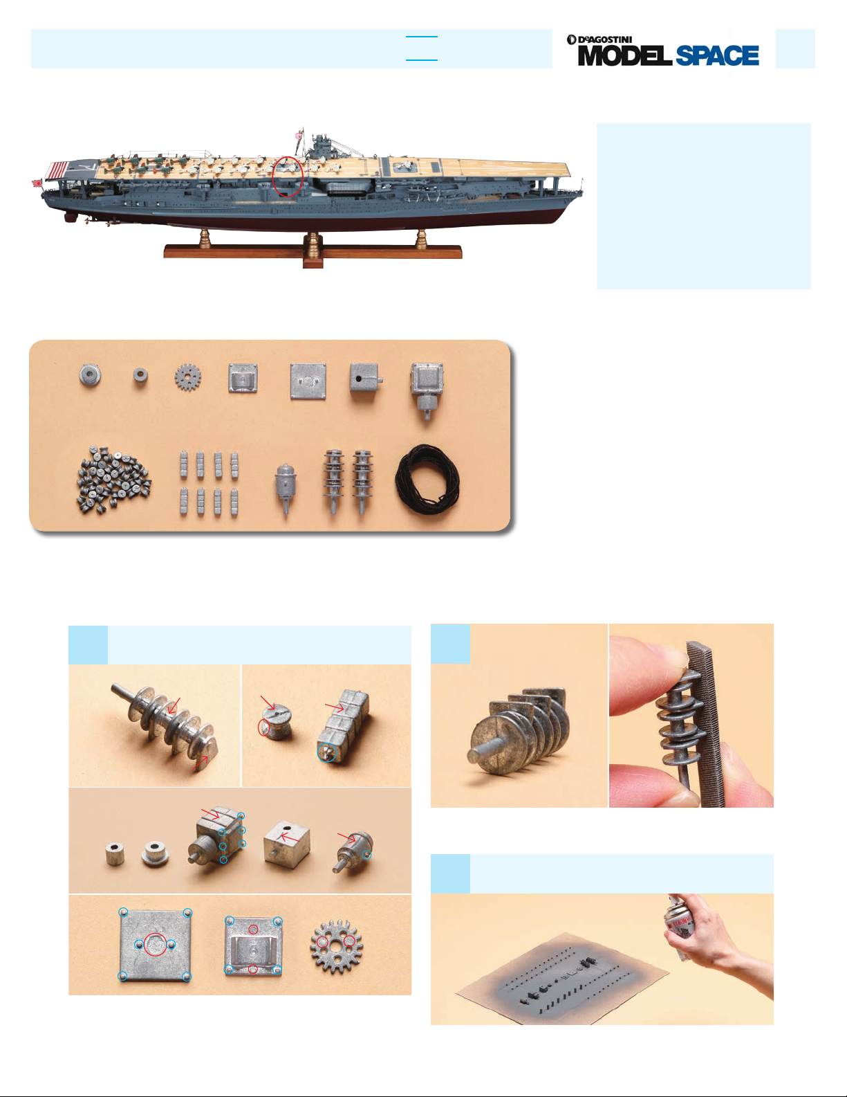
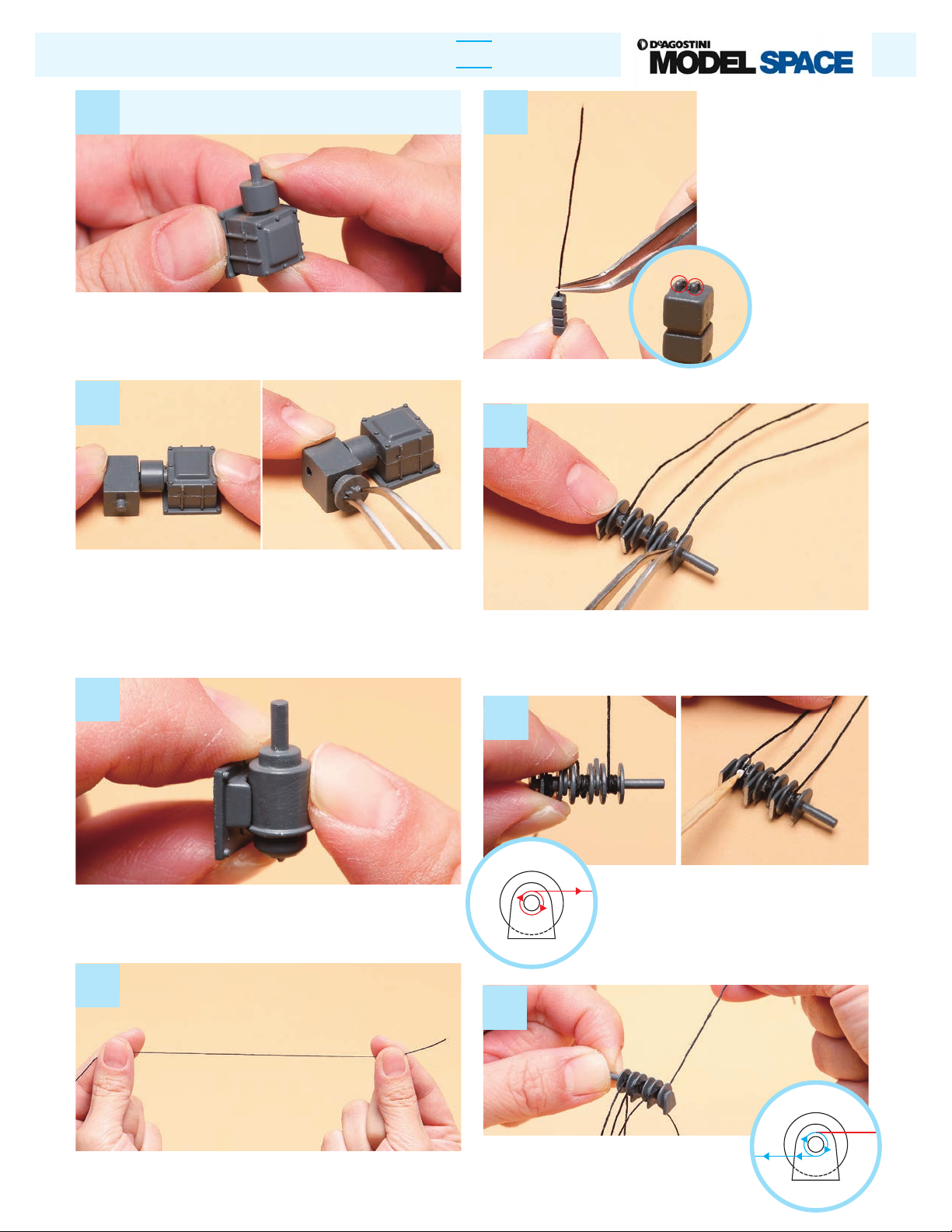
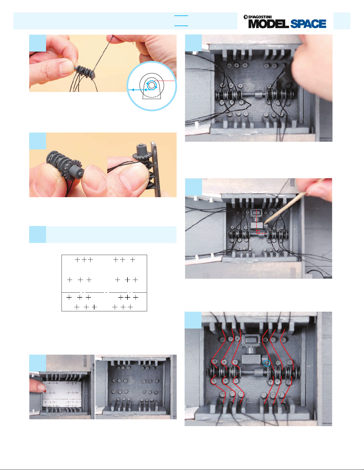
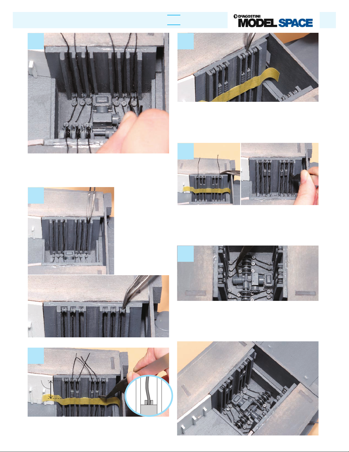
De Agostini Model Space IJN Akagi User manual


Other De Agostini Toy manuals

De Agostini
De Agostini Model Space HUMMER H1 User manual

De Agostini
De Agostini MODEL SPACE Honda CB750 FOUR User manual

De Agostini
De Agostini MODEL SPACE Honda CB750 FOUR User manual

De Agostini
De Agostini MODEL SPACE SUZUKI GSX 1300R HAYABUSA User manual

De Agostini
De Agostini Model Space T-72 User manual

De Agostini
De Agostini Model Space C57 User manual

De Agostini
De Agostini MODEL SPACE Honda CB750 FOUR User manual

De Agostini
De Agostini MODEL SPACE SUZUKI GSX 1300R HAYABUSA User manual

De Agostini
De Agostini Model Space MiG-29 User manual

De Agostini
De Agostini Model Space ROBI Pack 03 Instruction Manual

De Agostini
De Agostini Model Space SANTISIMA TRINIDAD User manual

De Agostini
De Agostini Model Space Harley-Davidson FLSTF Fat Boy User manual

De Agostini
De Agostini Model Space C57 User manual

De Agostini
De Agostini MODEL SPACE Honda CB750 FOUR User manual

De Agostini
De Agostini Model Space MiG-29 User manual

De Agostini
De Agostini MODEL SPACE Honda CB750 FOUR User manual

De Agostini
De Agostini Model Space H.M.S. Bounty Admiralty User manual

De Agostini
De Agostini Model Space T-72 User manual

De Agostini
De Agostini Model Space MiG-29 User manual

De Agostini
De Agostini MODEL SPACE Honda CB750 FOUR User manual


Popular Toy manuals by other brands


Carson
Carson Rapscallion brushless instruction manual

Carl Goldberg Products
Carl Goldberg Products Laser 200 instruction manual

Fisher-Price
Fisher-Price R8526 instruction sheet

Eduard
Eduard B-26 Marauder manual

Fisher-Price
Fisher-Price Laugh & Learn Learning Bunny K0468 quick start guide

THUNDER TIGER
THUNDER TIGER Mister Mulligan 4321 manual

Aircraft Modelers Research
Aircraft Modelers Research Extra 300 Mid-Wing manual

Eduard
Eduard M-ATV OGPK overhead cover manual

REVELL
REVELL P-47D Thunderbolt Razorback manual

IncrediBuilds
IncrediBuilds Animal Collection Koala Building instructions

LEGO
LEGO City 4441 Building instructions

Fisher-Price
Fisher-Price Thomas & Friends Take-n-Play Daring Dragon... instructions