manuals.online logo
Brands
  1. Home
  2. •
  3. Brands
  4. •
  5. De Agostini
  6. •
  7. Toy
  8. •
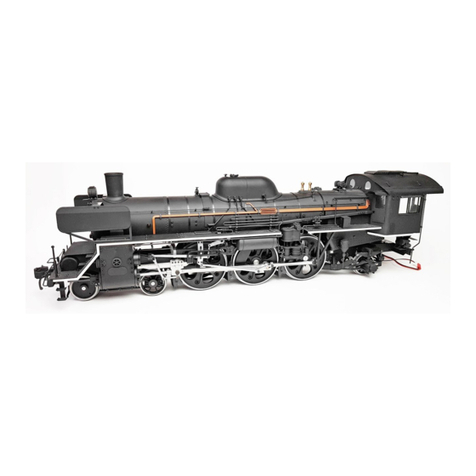
  9. De Agostini Model Space C57 User manual

De Agostini Model Space C57 User manual

Build the
Steam
Locomotive
Pack 05
Contents
Step by step Page
Editorial and design by Continuo Creative, 39-41 North Road, London N7 9DP.
Published in the UK by De Agostini UK Ltd, Battersea Studios 2, 82 Silverthorne Road, London SW8 3HE.
Published in the USA by De Agostini Publishing USA, Inc.,121 E. Calhoun Street, Woodstock, IL 60098.
All rights reserved © 2016
Warning: Not suitable for children under the age of 14. is product is not a toy and is not designed or
intended for use in play. Items may vary from those shown.
Build the
Steam
Locomotive
Stage 29: The leading truck 3
Stage 30: The leading truck 4
Stage 31: The headlamp
Stage 32: The smokebox door lock
Stage 33: The boiler 1
Stage 34: The boiler 2
Stage 35: The boiler 3
Stage 36: The rebox 1
68
70
72
74
76
78
81
83
Step by step: Stage
Tools
Where your parts t
68
29
The leading truck 3
Equaliser (outer) × 2
Equaliser (inner) × 2
Leaf springs × 2
Hanging links × 4
Nuts (M2) × 4
Screws (2 × 10mm) × 3
Hex head screws (2 × 8mm) × 5
Phillips screwdriver
Pliers
PVA glue
Socket wrench
1
Pass the threaded part of the link
through the hole in the leaf spring,
and tighten a nut onto it.
Lay out a leaf spring, two hanging links and
two nuts, as shown.
Repeat this process to create
two sets, as shown.
Equalisers
Your parts
69
23
The holes in the outer and
inner equalisers are dierent,
as shown above.
Place the equalisers on either side of the leaf
spring. Tighten a hex head screw through the
aligned holes of the outer equaliser, the links
and the inner equaliser.
Make a second set.
Place one of the leaf springs between an
inner and an outer equaliser, along with
two 2 × 8mm hex head screws.
4
Loosen the hex head screws
slightly and then apply some
PVA glue to the ends of them.
Place the assembly over the side frame of
the leading truck, with the equalisers either
side of the frame.
Threaded
Larger hole
without thread
Inner
Outer
Tighten a 2 × 10mm
screw into the hole in
the centre of the leaf
spring, to secure it to
the truck. Secure the
second leaf spring
assembly to the other
side of the truck in the
same way.
Complete
Step by step: Stage
Tools
Where your parts t
70
30
The leading truck 4
Leading wheel A
Leading wheel B (spoked)
Phillips screwdriver
Flat head driver
1
As well as the two leading
wheels from this stage, you will
also need the leading truck, as
well as the side stays, washers,
centre pin and 2 × 4mm screws
from Stage 28.
Make sure that when you are tting the wheels of the leading truck that you have the spoked
wheels at the rear (above left).
Side stays
Washers
Centre pin
Screws 2 × 4mm
Wheels
Your parts
71
2 3
Lay a side stay (Stage 28) over the
left underside of the truck, aligning
the holes (circled).
Tighten a 2 ×
4mm screw
(Stage 28)
into each of
the holes.
4
Place the leading
truck upside-
down and lower
the rst leading
wheels into the
U-shaped area
just behind the
guard irons.
Position the two axles
properly in the frames.
Fit the second
leading wheel
into the
U-shaped area
at the rear of
the truck in the
same way as
the rst wheels.
Pass the centre pin
(Stage 28) down through
the aligned holes.
Align the hole in the centre of
the leading truck with the hole
in the truck support.
Tighten the centre
pin into place.
Axles
Side stay
Washer
2 × 4mm screws
2 × 4mm screws
Fit another side stay to the other side of the
truck with four more 2 × 4mm screws.
Place a washer (Stage 28)
over the hole in the centre of
the truck support. Complete
Step by step: Stage
Tools
Where your parts t
72
31
The headlamp
Headlamp
Lens
Smokebox door handle
LED
Terminals × 2
Connector
Tweezers
Epoxy adhesive
Instant adhesive
1
HeadlampSmokebox door handle
Position the handle so that there is a 1mm
gap between it and the door.
Apply instant adhesive to the ends
of the handle to secure it in place.
Insert the handle into the two holes on the
smokebox door.
1mm
Your parts
73
2
4
3
Apply a small amount of
epoxy adhesive to the
base of the headlamp
(circled, above).
Pass the LED cable into the hole, down into
the smokebox, and then back to the right
side of the spark arrester.
Prepare the LED cable by removing
the cable tie. Straighten the end of the
cable that does not have the LED on it.
Insert the
post at the
bottom of the
headlamp
into the hole
at the top of
the smokebox
(circled).
Continue to feed the cable through the
hole until the LED is in the headlamp.
Align the end of the cable with the
hole in the headlamp.
Adjust the position
of the headlamp
to match the one
shown here. Make
sure it’s aligned
centrally with the
smokebox.
Epoxy adhesive
Complete
Step by step: Stage
Tools
Where your parts t
74
32
The smokebox
door lock
Lock bar
Smokebox door handle
Smokebox door lever
Lock
Superheater header
Handrail A
Handrail B
Handrail brackets × 5
Tweezers
Epoxy adhesive
Synthetic rubber adhesive
1
Smokebox door handle
Handrail
Your parts
Locate the two ridges on either side of
the inside of the smokebox door (circled).
Open the smokebox door, and insert the
lock bar from the front.
Glue the bar between the two ridges on
either side of the smokebox. The hole
in the centre should be positioned as
shown above.
Apply some epoxy adhesive to the space
between the ridges.
75
2
4
3
Turn the lever
onto the handle
as far as it will go.
Insert the end of the
smokebox handle into the
hole in the lever.
Pass the end of the handle into
the hole in the centre of the
smokebox door.
Apply some epoxy adhesive to
the end of the handle. Place the
lock onto the end of the handle.
Adjust the position of the
lock to match the one
shown above.
Apply synthetic
rubber adhesive
to the ends of
the two brackets
holding handrail
B, and insert them
into the two holes
(circled).
Place three
brackets on
handrail A, and
two onto handrail
B, as shown.
Move handrail
B through the
brackets and apply
synthetic rubber
adhesive to the
points where the
brackets were. Then
move the handrail
back into position.
When the lever is rotated
the lock on the inside of the
smokebox turns in the hole
in the centre of the lock bar,
holding the door shut.
Fit handrail A and the
three brackets in the
same way as B. Remove
any excess adhesive from
the rails and brackets.
Epoxy adhesive
Complete
Step by step: Stage
Tools
Where your parts t
76
33
The boiler 1
Lower boiler half
Boiler joints × 2
Screws (2 × 3mm) × 15
Phillips screwdriver
1
Boiler bottom
Place the boiler joints in front
of you, as shown. Identify the
outer and inner sides.
Your parts
Outside
Inside
Front
Hold a boiler joint up against the
lower boiler half, aligning the
circled holes of both parts.
77
2
3
The lower boiler half should now look like this.
Secure the boiler joint to
the lower boiler half with
seven 2 × 3mm screws.
These seven holes
should still be visible.
Fix the second boiler
joint to the other side of
the lower boiler half with
seven 2 × 3mm screws.
Complete
Step by step: Stage
Tools
Where your parts t
78
34
The boiler 2
1
Locate the six holes on the left and right
of the boiler upper half. Prepare six
handrail brackets and six nuts.
Insert a handrail bracket into
one of the holes.
Fit the remaining ve handrail brackets
to the other holes of the boiler upper
half. Before the adhesive dries, make
sure that the holes in the brackets are
aligned, as indicated by the red lines.
Apply some synthetic rubber adhesive
to the inside of the boiler half at the
base of the bracket, and tighten a nut
onto the end of it.
Boiler upper half
Water supply pipe
Safety valve
Handrail brackets × 10
Screws (2 × 4mm) × 5
Screws (2 × 3mm) × 13
Nuts (M2) × 10
Phillips screwdriver
Epoxy adhesive
Synthetic rubber adhesive
Tweezers
Toothpick
Boiler top Safety valve
Your parts
79
2
4 5
3
Apply epoxy adhesive to the underside of
the lip of the safety valve. Make sure the
hole is facing to the right of the boiler half,
then lower the valve into the circled hole.
Prepare two handrail brackets which
t into the two circled holes in the
smokebox, and two nuts which go
with the brackets.
Lower the
upper boiler
half onto the
lower boiler
half, aligninig
the holes of
both parts.
Tighten a 2 ×
3mm screw into
the four circled
holes on either
side of the
boiler.
Remove the screws
holding the boiler
joint in position.
Apply some synthetic
rubber adhesive to the
threaded part of the
handrail brackets and then
insert them into the two
circled holes and secure
with two nuts.
Apply synthetic rubber
adhesive to the step
(highlighted) on the
superheater header
(Stage 32), and place it
into the boiler joint.
Align the holes of the handrail brackets
before the adhesive dries.
Fit another two
handrail brackets
on the other side
of the smokebox.
Epoxy
adhesive
Boiler joint
Hold this way up
Synthetic rubber adhesive
Upper boiler half
Lower boiler half
Align at the front
Tap the four holes in the sides of the
joint (circles) with 2 × 3mm screws.
80
6 7
8 9
Place the boiler joint
into the front of the
boiler, aligning the
holes at the sides.
Apply synthetic rubber
adhesive to the inside of the
upper half of the boiler.
Insert the boiler
joint into the rear
of the smokebox.
Tighten the
four screws
removed in
Step 4 into the
holes in the
bottom of the
smokebox.
Apply a small
amount of
synthetic rubber
adhesive to the
end of the water
supply pipe and
insert it into the
hole in the valve.
Adjust the position
of the water supply
pipe so that it is
in front of the two
circled screws.
Tighten two more 2
× 3mm screws into
the two holes on
the other side.
Pass the end of the headlamp
cable through the hole in the top
of the superheater.
Tighten a 2 × 4mm
screw into each of
the four holes in the
bottom of the boiler.
If any synthetic
rubber adhesive
comes through
the seam between
the smokebox and
boiler, remove it
with a toothpick.
Tighten a 2 × 3mm
screw into the two
circled holes.
Hole
Complete
Step by step: Stage
Tools
Where your parts t
81
35
The boiler 3
Boiler (tapered section)
Safety valve cover
Safety valve base
Safety valves × 2
Screws (2 × 3mm) × 7
Phillips screwdriver
1
Boiler upper rear
Place the tapered section of the boiler, the safety valve base and safety valve cover out, as
shown above, to identify the fronts of each of the parts.
Higher at the rear
Higher at the front
Front
Your parts
82
4
2 3
Place the safety
valve base on
the inside of the
boiler section,
aligning the
circled holes.
Place the valve cover over
the top of the base, resting
on the boiler.
Fully tighten the
two screws.
Screw the two safety
valves into the holes in
the cover and base.
This is how the tapered
section of the boiler
should now look.
Half-tighten a 2 x
3mm screw into
each of the two
circled holes.
Place the tapered section of the boiler at the
back of the boiler, aligning the circled holes.
Tighten a 2 x 3mm
screw into the circled
holes on the left side
of the boiler.
Tighten two 2 x 3mm
screws into the holes
on the right side of the
boiler to secure the
tapered section of the
boiler in place.
Complete
Step by step: Stage
Tools
Where your parts t
83
36
The rebox 1
Fusible plugs × 4
Control valve lever
Handrail brackets × 2
Nuts (M2) × 2
Screws (2 × 3mm) × 6
Firebox joint
Control valve rod
Left rebox half
Phillips screwdriver
Synthetic rubber adhesive
Instant adhesive
Tweezers
1
Control valve lever Firebox (left)
Align the holes of the tapered
section of the boiler and the
control valve lever.
Tighten a 2 × 3mm screw
into the aligned holes.
Your parts
84
23
4 5
Align the holes in
the joint plate with
the holes in the left
rebox half.
The four holes are the locations for the
fusible plugs. Apply synthetic rubber
adhesive around the hole on the right on
the inside of the rebox half.
The two circled holes in the rebox
half are the locations for the handrail
brackets. Insert the rst bracket into
the hole as indicated.
Repeat this process for the remaining
three plugs.
Apply a drop of synthetic rubber
adhesive to the end of the bracket,
and then tighten a nut onto it.
Fit the second handrail bracket
in the same way. Before the
glue dries, make sure the holes
are aligned.
Align the circled
holes of the rebox
half with those of
the safety valve base
and boiler joint.
Tighten a 2 x 3mm
screw into the two
circled holes in the
rebox.
Tighten a 2 x 3mm
screw into the holes
in the rebox.
Apply instant adhesive to the
contact area between the plugs and
the inside of the rebox half.
Place the
rst plug
into the hole,
positioned as
shown.
Instant adhesive
Complete

Other manuals for Model Space C57

4

Other De Agostini Toy manuals

De Agostini Model Space C57 User manual

De Agostini

De Agostini Model Space C57 User manual

De Agostini MODEL SPACE SUZUKI GSX 1300R HAYABUSA User manual

De Agostini

De Agostini MODEL SPACE SUZUKI GSX 1300R HAYABUSA User manual

De Agostini Model Space MiG-29 User manual

De Agostini

De Agostini Model Space MiG-29 User manual

De Agostini Model Space MiG-29 User manual

De Agostini

De Agostini Model Space MiG-29 User manual

De Agostini Model Space D51 200 User manual

De Agostini

De Agostini Model Space D51 200 User manual

De Agostini MODEL SPACE Honda CB750 FOUR User manual

De Agostini

De Agostini MODEL SPACE Honda CB750 FOUR User manual

De Agostini Model Space T-72 User manual

De Agostini

De Agostini Model Space T-72 User manual

De Agostini Model Space MiG-29 User manual

De Agostini

De Agostini Model Space MiG-29 User manual

De Agostini Model Space T-72 User manual

De Agostini

De Agostini Model Space T-72 User manual

De Agostini Model Space T-72 User manual

De Agostini

De Agostini Model Space T-72 User manual

De Agostini Model Space T-72 User manual

De Agostini

De Agostini Model Space T-72 User manual

De Agostini MODEL SPACE Honda CB750 FOUR User manual

De Agostini

De Agostini MODEL SPACE Honda CB750 FOUR User manual

De Agostini Model Space T-72 User manual

De Agostini

De Agostini Model Space T-72 User manual

De Agostini Model Space T-72 User manual

De Agostini

De Agostini Model Space T-72 User manual

De Agostini Model Space H.M.S. Bounty Admiralty User manual

De Agostini

De Agostini Model Space H.M.S. Bounty Admiralty User manual

De Agostini MODEL SPACE Honda CB750 FOUR User manual

De Agostini

De Agostini MODEL SPACE Honda CB750 FOUR User manual

De Agostini Model Space T-72 User manual

De Agostini

De Agostini Model Space T-72 User manual

De Agostini MODEL SPACE Honda CB750 FOUR User manual

De Agostini

De Agostini MODEL SPACE Honda CB750 FOUR User manual

De Agostini Model Space MiG-29 User manual

De Agostini

De Agostini Model Space MiG-29 User manual

De Agostini Model Space ROBI Pack 03 Instruction Manual

De Agostini

De Agostini Model Space ROBI Pack 03 Instruction Manual

De Agostini Model Space D51 200 User manual

De Agostini

De Agostini Model Space D51 200 User manual

De Agostini Model Space C57 User manual

De Agostini

De Agostini Model Space C57 User manual

De Agostini Model Space MiG-29 User manual

De Agostini

De Agostini Model Space MiG-29 User manual

De Agostini Model Space MiG-29 User manual

De Agostini

De Agostini Model Space MiG-29 User manual

Popular Toy manuals by other brands
Costway TY327934 user manual

Costway

Costway TY327934 user manual

Hornet F/A-18 Assembly instructions

Hornet

Hornet F/A-18 Assembly instructions

Mattel Disney Frozen CGH15 instructions

Mattel

Mattel Disney Frozen CGH15 instructions

Horizon Hobby Night Vapor RTF instruction manual

Horizon Hobby

Horizon Hobby Night Vapor RTF instruction manual

Rail King AeroTrain Diesel Locomotive Operator's manual

Rail King

Rail King AeroTrain Diesel Locomotive Operator's manual

Nine Eagles NE C 210A instruction manual

Nine Eagles

Nine Eagles NE C 210A instruction manual

THUNDER TIGER hawk 1400 Assembly manual
THUNDER TIGER

THUNDER TIGER hawk 1400 Assembly manual

NOCH 14306 manual

NOCH

NOCH 14306 manual

juguettos Pasarela user guide

juguettos

juguettos Pasarela user guide

Freewing F9F-8 Cougar user manual

Freewing

Freewing F9F-8 Cougar user manual

Fisher-Price BOUNCE N GO Coupe G4815 manual

Fisher-Price

Fisher-Price BOUNCE N GO Coupe G4815 manual

DOCYKE S-04 Construction manual

DOCYKE

DOCYKE S-04 Construction manual

Mattel Pixel Chix Babysitter instructions

Mattel

Mattel Pixel Chix Babysitter instructions

Sawn Craft Zero 32 Assembly and setup manual

Sawn Craft

Sawn Craft Zero 32 Assembly and setup manual

Eduard 53 188 manual

Eduard

Eduard 53 188 manual

goliath Fish Food quick start guide

goliath

goliath Fish Food quick start guide

eRCMarket Millennium 90 IIse user manual

eRCMarket

eRCMarket Millennium 90 IIse user manual

Seagull Models AT-6 TEXAN Assembly manual

Seagull Models

Seagull Models AT-6 TEXAN Assembly manual

manuals.online logo
manuals.online logoBrands
  • About & Mission
  • Contact us
  • Privacy Policy
  • Terms and Conditions

Copyright 2025 Manuals.Online. All Rights Reserved.