manuals.online logo
Brands
  1. Home
  2. •
  3. Brands
  4. •
  5. De Agostini
  6. •
  7. Toy
  8. •
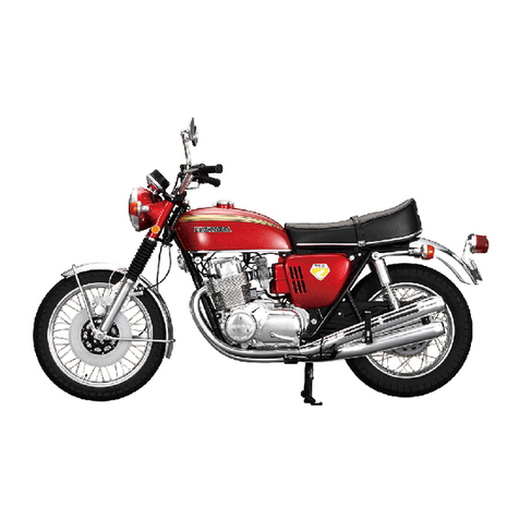
  9. De Agostini MODEL SPACE Honda CB750 FOUR User manual

De Agostini MODEL SPACE Honda CB750 FOUR User manual

01
BUILD YOUR OWN
Pack 15
TM
CONTENTS
Assembly Guide
Stage 48: The fuel cock and tank base
Stage 49: The left frame half
Stage 50: The horn
227
Editorial and design by Continuo Creative, 39-41 North Road, London N7 9DP.
Published in the UK by De Agostini UK Ltd, Battersea Studios 2,
82 Silverthorne Road, London SW8 3HE.
Published in the USA by De Agostini Publishing USA, Inc., 915 Broadway,
Suite 609, New York, NY 10010.
All rights reserved © 2015
Warning: Not suitable for children under the age of 14. is product is not a toy
and is not designed or intended for use in play. Items may vary from those shown.
TM
www.model-space.com
227
Honda CB750 FOUR: Assembly Guide
Stage 48
Fuel tank base (right)
Fuel cock A
Fuel cock B
Washers × 2
Screws (type A) × 2
Screws (type G) × 3
Rear brake spindle
Switch box
Fuel cock tube A
Fuel cock tube B
The fuel cock and
tank base
Tools Prepare
Phillips screwdriver Right frame half (Stage 36)
Masking tape
Pliers
Paper towel
File
Locate the recess in the open end of
fuel cock A, and the corresponding
projection on the side of fuel cock B
(both circled).
Push fuel cock B into fuel cock A.
Locate the U-shaped recess in the fuel
tank base (right) and align the projection
on the end of fuel cock B with the hole in
the recess.
Push the fuel cock into the fuel tank
base (right).
Fuel cock A
Fuel cock B
Your parts
1
2
3
4
228
Honda CB750 FOUR: Assembly Guide
Insert a type G screw into one of
the washers.
Locate the holes in
the right frame half
(Stage 36). Check
the holes for any burrs or pieces of ash
left over from the casting process, such
as those circled in the inset. Turn the screw into the washer.
Push the projections into the holes.
Tighten one of the type G screws with
washer attached (from Step 9) into the
hole nearer the front of the frame half.
Use a le to remove any burrs or ash
you have found in the holes.
Repeat the process to combine another
type G screw and washer.
Take the fuel tank base and align the
projections with the corresponding
holes on the underside of the frame half,
as indicated by the arrows.
5
6
7
8
9
10
11
12
229
Honda CB750 FOUR: Assembly Guide
Take the rear brake spindle and align the
semi-circular hole with the semi-circular
projection of the rear brake pedal.
Screw the second type G screw and
washer into the hole nearer the rear of
the frame half. Push the spindle onto the rear brake
pedal.
Remove the masking tape from around
the bottom of the right frame half. Make
sure the brake pedal stays in place.
Push the rear brake into the spindle to
fully engage the two parts.
If the rear brake spindle doesn’t fit
If you have trouble tting the rear brake spindle onto the projection of the rear brake, you may need to open the hole in the
spindle up a bit more.
Inside of the hole of the rear brake
spindle are two raised parts that help
to hold it in place. You should avoid
altering these.
Use a le to reduce the thickness of the
wall of the other side of the hole, all the
way through.
When combining the spindle and
pedal, cover them with paper towel
and carefully squeeze together with
pliers. If the spindle still won’t t,
reduce the wall thickness a little more.
13
14
15
16
17
230
Honda CB750 FOUR: Assembly Guide
Turn the U-shaped end of the switch box
around and align it with the raised hole
in the frame.
The brake pedal and spindle should now
be engaged, as shown.
Temporarily secure the switch box cable
to the frame with masking tape.
Tighten the type A screw into the hole.
The head of the screw will hold the
U-shaped end of the switch box in place.
Insert a type A screw into the hole in the
frame, where the U-shaped end of the
switch box is.
Insert the projection of the switch box
into the hole in the frame (green arrow).
When you push the brake pedal down,
the end of the spindle will hit the button
in the switch box (inset). When all the
wiring is connected, this will activate the
brake light.
Stage complete
18
19
20
21
22
23
24
231
Honda CB750 FOUR: Assembly Guide
Tools Prepare
Your parts
Left frame half
Washers × 2
Screws (type J) × 3
The left frame half
Phillips screwdriver
Tweezers
Needle-nose pliers
Cross wrench
File
Carburettor (Stage 17)
Air lter case (Stage 25)
Centre stand (Stage 37)
Engine (Stage 47)
Right frame half (Stage 48)
Screws (type E) × 3 (Stage 32)
Screws (type Q) × 2 (Stage 32)
Fuel cock tube A(Stage 48)
Fuel cock tube B (Stage 48)
Instant adhesive
You will need the carburettor from Stage
17, the air lter from Stage 25, the centre
stand from Stage 37, and the engine
from Stage 47.
Align the projections at the ends of the
carburettor with the holes in the air lter.
Push the projections into the holes,
as shown.
Place the end of fuel cock tube A (from
Stage 48) over the circled hole in
the carburettor.
Stage 49
1
2
3
4
232
Honda CB750 FOUR: Assembly Guide
Push the tube into the hole until it stopsPush the tube into the hole until it stops.
The two fuel cock tubes should now look
like this.
Bring together the four tubes attached
to the bottom of the carburettor.
Insert the ends of the four tubes into
the hole from which the IR sensor cable
is projecting.
Place the end of fuel cock tube B into the
other hole in the carburettor (circled).
Align the projections of the carburettor
with the four corresponding holes in the
rear of the cylinders.
Push the carburettor into place.
Fuel cock tube B (long)
Fuel cock tube A (short)
5
6
7 8
9
10
11
12
233
Honda CB750 FOUR: Assembly Guide
Place the two frame halves next to each other, as shown. Locate the matching
screw holes (circled) on both.
Push the four tubes into the hole, as
shown above.
When viewed from the side, your
assembly should now look like this.
Place the engine on a at surface so that the right side is facing up. Then place the
right frame half over the engine.
Check each of the holes for burrs or ash,
and remove any you nd with a le.
Push the pin at the top of the air lter
into the corresponding hole in the
frame half.
Left Right
13
14
15
16
17
18
234
Honda CB750 FOUR: Assembly Guide
Place a type E screw into the aligned
holes at the rear of the crankcase.
Align the circled hole in the right
frame half with the hole at the rear of
the crankcase.
After a while, the wrench may start to
slip. At this point, you should use pliers
to tighten the screw further.
Place a type Q screw into the aligned
holes at the front of the crankcase.
Tighten the type E screw into place.Then align this circled hole in the
frame half with the hole at the front of
the crankcase.
Use the cross wrench to tighten the type
Q screw into place.
The engine and air lter will now be secured to
the right frame half, as shown.
19
20
21
22
23
24
25
26
235
Honda CB750 FOUR: Assembly Guide
Using tweezers, remove the fuel cock
from the fuel tank base and pull the
two fuel cock tubes out to the right of
the engine. Apply a small amount of instant adhesive
to the highlighted projections on the
fuel cock.
Place the circled hole of the left frame
half over the projection at the side of the
centre stand.
Push the free ends of the tubes onto the
projections on the fuel cock.
Place the hole at the top of the left frame
half onto the projection of the air lter,
as shown. Then align the holes in the
frame with those at the front and rear of
the crankcase.
Glue the fuel cock back into position on
the underside of the tank base.
Place the left frame over the left side of
the engine.
Turn the frame over and place the
projection at the side of the centre stand
into the circled hole.
Fuel cock
tube B (long)
Fuel cock
tube A (short)
27
28
29
30
31
32
33
34
236
Honda CB750 FOUR: Assembly Guide
Place a type Q screw into the aligned holes at the front
of the crankcase.
Place a type E screw into the aligned holes at the rear
of the crankcase.
Turn the type Q screw into place.
Turn the type E screw into place, but leave it a bit
loose to allow for easy removal during later assembly
stages.
35 36
37 38
237
Honda CB750 FOUR: Assembly Guide
Tighten the type E screw into place, again leaving it a
bit loose.
As before, leave the screw a bit loose to allow for easy
removal during later assembly stages.
Place a type E screw into the aligned holes of the two
frame halves, behind the engine.
Stage complete
39 40
41
238
Honda CB750 FOUR: Assembly Guide
Tools Prepare
Your parts
Horn
Rear left indicator
Screws (type G) × 2
The horn
Phillips screwdriver
Cross wrench
Main frame (Stage 49)
Masking tape
Plastic bag
Remove the two type E screws and the
type Q screw holding the left frame half
in place.
Align the projections on the horn with
the holes at the front of the left frame
half (arrowed).
Push the projections into the holes
(circled).
Insert a type G screw into the aligned
holes of the frame half and horn.
Stage 50
1
2
3
4
239
Honda CB750 FOUR: Assembly Guide
Keeping the cable within the circular
hole, gently pull it to bring the indicator
closer to the frame.
Tighten the type G screw into place.
Align the square projection on the
forward edge of the indicator with the
corresponding notch in the frame.
Take the rear left indicator and place the
cable through the circled gap at the end
of the frame half.
Push the indicator into the hole in the
frame.
Using masking tape, temporarily secure
the indicator cable to the left frame half.
5
6
7
8
9
10
Stage complete
20
Honda CB750 FOUR:
TM

Other manuals for MODEL SPACE Honda CB750 FOUR

7

Other De Agostini Toy manuals

De Agostini Millennium Falcon 3 Series User manual

De Agostini

De Agostini Millennium Falcon 3 Series User manual

De Agostini MODEL SPACE Soleil Royal User manual

De Agostini

De Agostini MODEL SPACE Soleil Royal User manual

De Agostini Model Space C57 User manual

De Agostini

De Agostini Model Space C57 User manual

De Agostini Model Space MiG-29 User manual

De Agostini

De Agostini Model Space MiG-29 User manual

De Agostini MODEL SPACE Honda CB750 FOUR User manual

De Agostini

De Agostini MODEL SPACE Honda CB750 FOUR User manual

De Agostini Model Space ROBI Pack 03 Instruction Manual

De Agostini

De Agostini Model Space ROBI Pack 03 Instruction Manual

De Agostini MODEL SPACE Honda CB750 FOUR User manual

De Agostini

De Agostini MODEL SPACE Honda CB750 FOUR User manual

De Agostini Model Space MiG-29 User manual

De Agostini

De Agostini Model Space MiG-29 User manual

De Agostini Model Space T-72 User manual

De Agostini

De Agostini Model Space T-72 User manual

De Agostini Model Space T-72 User manual

De Agostini

De Agostini Model Space T-72 User manual

De Agostini Model Space H.M.S. Bounty Admiralty User manual

De Agostini

De Agostini Model Space H.M.S. Bounty Admiralty User manual

De Agostini Model Space MiG-29 User manual

De Agostini

De Agostini Model Space MiG-29 User manual

De Agostini Model Space T-72 User manual

De Agostini

De Agostini Model Space T-72 User manual

De Agostini Model Space T-72 User manual

De Agostini

De Agostini Model Space T-72 User manual

De Agostini Model Space MiG-29 User manual

De Agostini

De Agostini Model Space MiG-29 User manual

De Agostini Model Space T-72 User manual

De Agostini

De Agostini Model Space T-72 User manual

De Agostini Model Space C57 User manual

De Agostini

De Agostini Model Space C57 User manual

De Agostini Model Space HUMMER H1 User manual

De Agostini

De Agostini Model Space HUMMER H1 User manual

De Agostini MODEL SPACE Honda CB750 FOUR User manual

De Agostini

De Agostini MODEL SPACE Honda CB750 FOUR User manual

De Agostini MODEL SPACE Honda CB750 FOUR User manual

De Agostini

De Agostini MODEL SPACE Honda CB750 FOUR User manual

De Agostini Model Space C57 User manual

De Agostini

De Agostini Model Space C57 User manual

De Agostini MODEL SPACE SUZUKI GSX 1300R HAYABUSA User manual

De Agostini

De Agostini MODEL SPACE SUZUKI GSX 1300R HAYABUSA User manual

De Agostini Model Space D51 200 User manual

De Agostini

De Agostini Model Space D51 200 User manual

De Agostini Model Space T-72 User manual

De Agostini

De Agostini Model Space T-72 User manual

Popular Toy manuals by other brands

HD Inept ELB0101 Assembly instructions

HD

HD Inept ELB0101 Assembly instructions

Dancing Wings Hobby S20 1.2M Fokker-E instruction manual

Dancing Wings Hobby

Dancing Wings Hobby S20 1.2M Fokker-E instruction manual

Mattel Enchantimals FRH50 Assembly

Mattel

Mattel Enchantimals FRH50 Assembly

Arrows Hobby 620 MM PIONEER operating manual

Arrows Hobby

Arrows Hobby 620 MM PIONEER operating manual

Eduard GMC Bofors 40mm manual

Eduard

Eduard GMC Bofors 40mm manual

Staufenbiel L-13 BLANIK instruction manual

Staufenbiel

Staufenbiel L-13 BLANIK instruction manual

Viessmann 1969 Operation manual

Viessmann

Viessmann 1969 Operation manual

marklin 26566 instruction manual

marklin

marklin 26566 instruction manual

Mattel PIXEL CHIX H8330 user manual

Mattel

Mattel PIXEL CHIX H8330 user manual

Eduard BAC Lightning F.2A/F.6 exterior quick start guide

Eduard

Eduard BAC Lightning F.2A/F.6 exterior quick start guide

Smoby Frozen Ice Cream Shop Assembly instructions

Smoby

Smoby Frozen Ice Cream Shop Assembly instructions

AerodromeRC Fokker Dr.1 46.7" instructions

AerodromeRC

AerodromeRC Fokker Dr.1 46.7" instructions

Horizon Hobby AerBird3 instruction manual

Horizon Hobby

Horizon Hobby AerBird3 instruction manual

Zapf Creation Baby born  Brother User instructions

Zapf Creation

Zapf Creation Baby born Brother User instructions

Faller Saloon Shooting Stand Assembly instructions

Faller

Faller Saloon Shooting Stand Assembly instructions

REVELL Fokker D VII Assembly manual

REVELL

REVELL Fokker D VII Assembly manual

Rail King The Silver Bullet 3V PS2 Operation manual

Rail King

Rail King The Silver Bullet 3V PS2 Operation manual

LeapFrog LeapBuilders 123 Counting Train Parents' guide

LeapFrog

LeapFrog LeapBuilders 123 Counting Train Parents' guide

manuals.online logo
manuals.online logoBrands
  • About & Mission
  • Contact us
  • Privacy Policy
  • Terms and Conditions

Copyright 2025 Manuals.Online. All Rights Reserved.