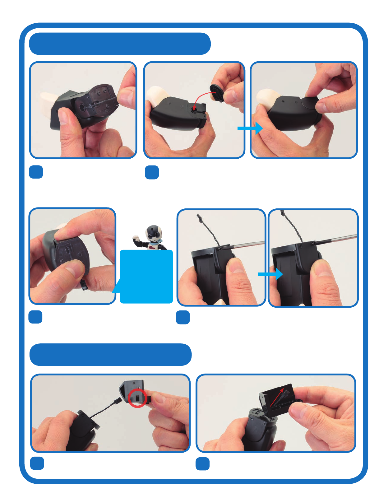
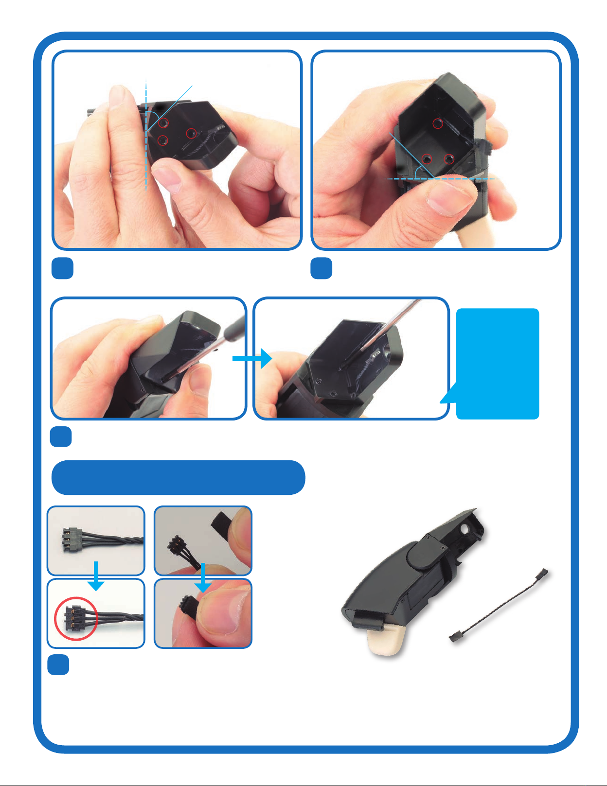
De Agostini Model Space ROBI Pack 03 Instruction Manual


Other De Agostini Toy manuals

De Agostini
De Agostini Model Space Harley-Davidson FLSTF Fat Boy User manual

De Agostini
De Agostini Model Space MiG-29 User manual

De Agostini
De Agostini Model Space MiG-29 User manual

De Agostini
De Agostini MODEL SPACE Honda CB750 FOUR User manual

De Agostini
De Agostini MODEL SPACE SUZUKI GSX 1300R HAYABUSA User manual

De Agostini
De Agostini Model Space D51 200 User manual

De Agostini
De Agostini Model Space IJN Akagi User manual

De Agostini
De Agostini Model Space SANTISIMA TRINIDAD User manual

De Agostini
De Agostini Model Space MiG-29 User manual

De Agostini
De Agostini Model Space D51 200 User manual

De Agostini
De Agostini Model Space C57 User manual

De Agostini
De Agostini Model Space T-72 User manual

De Agostini
De Agostini Model Space T-72 User manual

De Agostini
De Agostini MODEL SPACE Honda CB750 FOUR User manual

De Agostini
De Agostini MODEL SPACE Honda CB750 FOUR User manual

De Agostini
De Agostini Model Space MiG-29 User manual

De Agostini
De Agostini MODEL SPACE Honda CB750 FOUR User manual

De Agostini
De Agostini Model Space T-72 User manual

De Agostini
De Agostini Model Space HUMMER H1 User manual

De Agostini
De Agostini Model Space C57 User manual


Popular Toy manuals by other brands


Smoby
Smoby 7600220376 quick start guide

Eduard
Eduard Nashorn quick start guide

electrifly
electrifly L-39 instruction manual

Agora Models
Agora Models JAGUAR E-TYPE Build instructions

TP active fun
TP active fun TP295 Instructions for assembly, maintenance and safe use

The Learning Journey
The Learning Journey Techno Gears Bionic Bug instruction manual


