manuals.online logo
Brands
  1. Home
  2. •
  3. Brands
  4. •
  5. De Agostini
  6. •
  7. Toy
  8. •
  9. De Agostini Model Space C57 User manual

De Agostini Model Space C57 User manual

Build the
Steam
Locomotive
Pack 11
Contents
Step by step Page
Editorial and design by Continuo Creative, 39-41 North Road, London N7 9DP.
Published in the UK by De Agostini UK Ltd, Battersea Studios 2, 82 Silverthorne Road, London SW8 3HE.
Published in the USA by De Agostini Publishing USA, Inc.,121 E. Calhoun Street, Woodstock, IL 60098.
All rights reserved © 2016
Warning: Not suitable for children under the age of 14. is product is not a toy and is not designed or
intended for use in play. Items may vary from those shown.
Build the
Steam
Locomotive
Stage 83: Detailing the tender 4
Stage 84: The base 1
Stage 85: The base 2
Stage 86: The base 3
Stage 87: The base top
Stage 88: The speaker
Stage 89: The switchboard and battery box
Stage 90: The sound eects generator
Stage 91: The track
190
192
194
196
198
200
202
204
206
Tools
Where your parts t
190
Step by step: Stage 83
Detailing the tender 4
Tender upper plate
Buer
Coupling buer
Brake hose
Drawbar pin
Screws (2 x 4mm) x 7
Phillips screwdriver
Synthetic rubber adhesive (SRA)
Tweezers
Pliers
1
Familiarise yourself with the coupling
buer using the photo above as a guide.
Line the part up to the circled holes at the
rear of the tender.
Use two 2 x 4mm screws to secure it.
Your parts
Shorter side on top
Tender upper plate Brake hoseBuer
191
Your assembly
should look like
this.
Complete
Instant adhesive
54
2
Lower the
tender upper
plate into the
top of the
tender, as
shown.
Turn the tender
upside down and
t the drawbar
pin into the
circled hole using
tweezers. You can
remove the front
truck to make
this easier.
Now line up the
buer to the
circled holes at
the front of the
tender. It does
not matter
which way
round it goes.
Use pliers to
tighten the pin
into place.
Use two 2 x 4mm
screws to secure
the upper plate to
the tender via the
circled holes.
Use two more
2 x 4mm screws to
secure the buer
to the tender.
3
Fit the brake hose,
positioned as
shown on the rear
of the tender, into
the circled hole and
secure with SRA.
Once everything
is in place,
reinforce the
brake hose from
the back, using
instant adhesive.
Your assembly
should look
like this.
Now take the
overow pipe
from Stage 81
and use SRA to
secure it via the
two circled holes.
Forward Front
Overhang at bottom
Complete
Tools
Where your parts t
192
Step by step: Stage 84
The base 1
Front end frame
Side frame A
Side frame B
Frame joint
Cap bolts x 8
Hex wrench
1
Familiarise yourself
with side frames A
and B.
Now do the same for
the front end frame and
frame joint.
Longer space between
holes and frame ends
Painted edge on top
Frame joint
Frame joint
Front end frame
Front end frame
Indent
Front Front
Front
Front
A
A
B
B
Your parts
Work of this issue
Front base section
Hex wrench
193
2
4
3
Lay out all four parts as shown above.
Lay the base face down on a at surface to ensure all the holes are aligned,
then secure the frame joint with four half-tightened cap bolts.
Line up the holes at each joint,
and insert a cap bolt into each.
Then use the hex wrench to
further tighten the bolts – but
only lightly at this stage to allow
room for adjustment.
Tighten the cap bolts by hand, as far
as you can.
Painted top faces down
All parts upside down
B
A
Front end
frame
Complete
Indent
Tools
Where your parts t
194
Step by step: Stage 85
The base 2
Frame joint
Side frame C
Side frame D
Rear end frame
Hex bolts x 8
Hex wrench
1
Note the dierence
between the side
frames C and D –
there is a long hole
in D.
Now do the same for the rear
end frame and frame joint.
Your parts
Rear
Long hole
Painted tops
Rear base section
This stage’s parts
Front
Frame joint
Rear end frame
C
D
195
2
4
3
Complete
Rear
Lay out all four parts as shown above.
Lay the base face down on a at surface to ensure all the holes are aligned,
then secure the frame joint with four half-tightened cap bolts.
Line up the holes at each joint,
and insert a cap bolt into each.
Then use the hex wrench to further
tighten the bolts – but only lightly
at this stage to allow room for
adjustment later.
Tighten the cap bolts by hand, as far
as you can.
Painted top faces down
All parts upside down
D
C
Indent
Tools
Where your parts t
196
Step by step: Stage 86
The base 3
Side frames E x 3
Frame joint
Side frame F
Cap bolts x 16
Hex wrench
1
Note the dierence between the three side frames E and the single F. There is an indent cut
into frame F.
E
F
Your parts
Indent
Front
Middle base section
This stage’s parts
197
2
4
3
Lay out this stage’s parts, along with the front and rear base sections, upside
down on your work surface as shown.
Lay the assembly out on a at surface and connect the central section to the
two end sections. Then tighten all 16 cap bolts fully.
Complete
Front
EE
E F
Indents
Front base
section
Rear base
section
Indents
Indent
Long hole
Long hole
Front
All parts upside down Line up the holes in the side frames with
those in the centre joint, and insert a cap
bolt into each.
Then use the hex wrench to further
tighten the bolts – but only lightly
at this stage to allow room for
adjustment. Repeat this for all sides
(E and F).
Tighten the cap bolts by hand, as far
as you can.
Tools
Where your parts t
198
Step by step: Stage 87
Top plate A
Top plate B
Top plate C
Top plate D
Cap bolts x 16
Hex wrench
1
The above photo shows how the base’s top plates will t, so make a note of their order and
orientations.
A
D
B
B
C
C
D
A
Your parts
Small holes
Long hole
Speaker holes slightly towards front of plate Hole towards centre
Front
Top plates
The base top
199
2
4
3
Each top plate has four bolt holes that will match up to those on the frames,
as shown. Lay these plates out now.
Fit all 16 cap bolts by hand and then fully tighten once all are in place to
secure the top plates.
Fit the cap bolts by hand.
Then continue tightening with the hex
wrench, but not fully.
Tighten by hand as
far as you can.
Complete
Front
Tools
Where your parts t
200
Step by step: Stage 88
1
Turn the base upside down and locate
the speaker holes.
Place the speaker protector
onto the base so it covers
the speaker holes, but
not the four circled ones.
Smooth any wrinkles out.
Speaker (underside)
Your parts
The speaker
Speaker
Speaker cover
Speaker protector
Speaker cable
Speaker screws x 11
Tweezers
201
3
Complete
2
Lower the speaker
cover onto the
speaker. It does
not matter which
way round it goes,
but be careful not
to trap any wiring.
Secure the cover
with six more
speaker screws.
4
Use tweezers to slot
the speaker’s circuit
board into the mount
at the end of the
speaker housing.
Use four of the speaker screws
to secure it.
Lay the speaker down over
the protector, so that the
four holes at the edges
match those in the plate.
Feed the speaker cable through the
slot in the frame joint, then plug its
connector into the socket.
Make sure the part is tted securely.
Front Socket
Pins at top of connector
Tools
Where your parts t
202
Step by step: Stage 89
The switchboard
and battery box
Battery box
Battery box cover
Switchplate
Switchboard
Switches
Motor cable
Battery cable
Light cable
Hex nuts x 10
Washers x 5
Screws (2.6 x 8mm) x 5
Screws (2.3 x 8mm) x 6
Tweezers
Phillips screwdriver
Pliers
(Optional)
Synthetic rubber adhesive (SRA)
1
Locate the pin and tab on each washer
before you use it.
Lay the switchboard with its at face down,
then t the washers to it as shown above.
There is no need to fully adhere
the washers, but a dot of SRA will
help hold them in place for the
rest of the assembly.
Your parts
Battery box (underneath)
Switches
Tab
Tabs in these holes
Pin
203
23
4
Fit a hex nut over each of the
switches. Now line up the switches, with the
pin/groove side facing up, to the
switchplate, as shown.
Now t the switchplate to the
long rectangular hole in the
side of the base, as shown.
Use four of the smaller screws (2.3
x 8mm) to secure the plate.
Lay the switches out by the
switchboard, as shown – none
of the wires should cross. The
ridges on the connector block
should be positioned at the top.
Turn the hex nut until the end
of the threaded part of the
switch is ush with it.
Turn the nuts onto the threaded
part of the switches to about two
thirds of the way in.
Hold the parts together, then
place a hex nut onto the thread
of the rst switch.
Fit the switches into the washers, one by
one. The grooves through the threaded
section of the switches and the pin on
the washers will orient the parts.
Tighten the rear hex nut until the
switch is held securely in place. Then
repeat for the other four switches.
Complete
Ridges at top
Groove
Pin
Ridges at top
Wires must not
cross!
Pins/grooves
Flush
Front
Tools
Where your parts t
204
Step by step: Stage 90
The sound eects
generator
1
Line the generator up to the circled
holes on the underside of the base.
Secure the generator
with four screws.
The sound eects generator has ve sockets,
which are labelled in English.
Sound
eects
generator
Your parts
Sound eects generator
Generator screws x 5
Phillips screwdriver
205
2 3
Take the wide connector leading from
the switches and t it into the socket
marked SWITCHES. Then take the
smaller connector leading from the
speaker and plug it into the socket
marked SPEAKER.
Now take Stage 89’s battery box and,
making sure its connectors are facing
towards the generator, lower it into
the base.
Fetch the 2.6 x 8mm screws from
Stage 89, and use them to ax the
battery box.
Now use the smaller-headed 2.3 x
8mm) screws from Stage 89 to secure
the lid.
Complete
4
Use the photo
to dierentiate
between the
three cables
supplied with
Stage 89. Top to
bottom, these are
the motor cable,
battery cable and
light cable.
Battery box position
The battery box is hidden on the underside
of the base, but if you’d rather have it
more readily accessible, you can leave it
unattached, with the wires tracing through
the notch indicated below.
Plug the small white
connectors of each into
their relevant, marked
sockets on the sound
eects generator.
Connectors
Small, white
connectors
Long,
red
Large,
black
Small, beige
Notch
Now feed the
cables’other ends
through the slot
in the frame joint.
The battery cable’s
black connector
can be tted to the
connectors on the
battery box, while
the other two should
be fed through the
indicated hole in the
top of the base.
Tools
Where your parts t
206
Step by step: Stage 91
Ballasts A x 2
Ballasts B x 17
Ballasts C x 2
Ballasts D x 2
Sleepers x 20
Rail fasteners x 42
Long rails x 4
Short rails x 2
1
Lay a ballast A at the front end of the base,
then place a ballast B next to it.
Lay four more ballasts B (making ve in
total), then place a ballast C, as shown.
A C
D
B
Your parts
Now lay all the remaining ballasts, using the photo above as a guide.
Rails
Sleepers Ballast
Longer arm
Long arms
Front
Front
B
A
B x 5
C
B x 5 C x 2 B x 3 B x 9
D x 2
AA
The track
207
2 3
Lay the rst sleepers into the gaps
between the ballast pieces, starting
at the front. It does not matter which
way round the parts go.
Now begin tting the rail fasteners. Each
one has two pins on its underside, which
will t into the sleepers’holes, as shown.
Fit all the fasteners.
4
Do this for
all the rails,
making sure
there is no
visible gap
where the
paired longer
rails meet.
The above photo shows where the long and short
rails will go.
The rails will be
tted by sliding
them through
the fasteners,
one by one.
6 14
Lay six at the front, and 14 at the rear, in each of the thinner ballast holes.
Short x 2 Long x 4
Complete

Other manuals for Model Space C57

4

Other De Agostini Toy manuals

De Agostini Model Space MiG-29 User manual

De Agostini

De Agostini Model Space MiG-29 User manual

De Agostini Model Space T-72 User manual
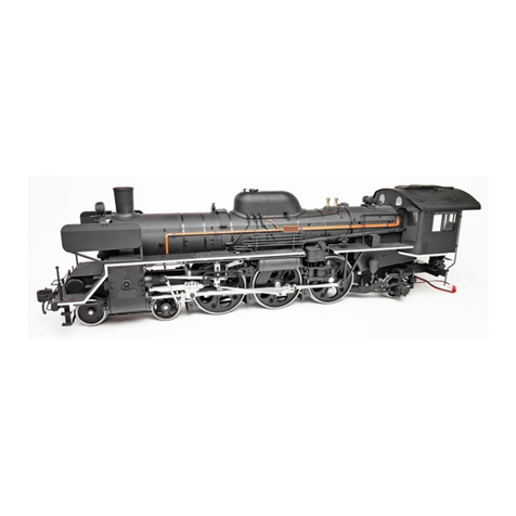
De Agostini

De Agostini Model Space T-72 User manual

De Agostini Model Space C57 User manual

De Agostini

De Agostini Model Space C57 User manual

De Agostini MODEL SPACE Soleil Royal User manual

De Agostini

De Agostini MODEL SPACE Soleil Royal User manual

De Agostini Model Space C57 User manual

De Agostini

De Agostini Model Space C57 User manual

De Agostini Model Space T-72 User manual

De Agostini

De Agostini Model Space T-72 User manual

De Agostini Model Space MiG-29 User manual

De Agostini

De Agostini Model Space MiG-29 User manual

De Agostini Model Space MiG-29 User manual

De Agostini

De Agostini Model Space MiG-29 User manual

De Agostini MODEL SPACE Honda CB750 FOUR User manual

De Agostini

De Agostini MODEL SPACE Honda CB750 FOUR User manual

De Agostini Model Space MiG-29 User manual

De Agostini

De Agostini Model Space MiG-29 User manual

De Agostini Model Space D51 200 User manual

De Agostini

De Agostini Model Space D51 200 User manual

De Agostini Model Space T-72 User manual

De Agostini

De Agostini Model Space T-72 User manual

De Agostini Model Space T-72 User manual

De Agostini

De Agostini Model Space T-72 User manual

De Agostini Model Space MiG-29 User manual

De Agostini

De Agostini Model Space MiG-29 User manual

De Agostini Model Space C57 User manual

De Agostini

De Agostini Model Space C57 User manual

De Agostini MODEL SPACE Honda CB750 FOUR User manual

De Agostini

De Agostini MODEL SPACE Honda CB750 FOUR User manual

De Agostini Model Space T-72 User manual

De Agostini

De Agostini Model Space T-72 User manual

De Agostini MODEL SPACE Honda CB750 FOUR User manual

De Agostini

De Agostini MODEL SPACE Honda CB750 FOUR User manual

De Agostini Model Space T-72 User manual

De Agostini

De Agostini Model Space T-72 User manual

De Agostini Model Space MiG-29 User manual

De Agostini

De Agostini Model Space MiG-29 User manual

De Agostini MODEL SPACE Honda CB750 FOUR User manual

De Agostini

De Agostini MODEL SPACE Honda CB750 FOUR User manual

De Agostini Millennium Falcon 3 Series User manual

De Agostini

De Agostini Millennium Falcon 3 Series User manual

De Agostini Model Space H.M.S. Bounty Admiralty User manual

De Agostini

De Agostini Model Space H.M.S. Bounty Admiralty User manual

De Agostini Model Space ROBI Pack 03 Instruction Manual

De Agostini

De Agostini Model Space ROBI Pack 03 Instruction Manual

Popular Toy manuals by other brands
LEGO FIRST LEGO League Challenge City Shaper manual

LEGO

LEGO FIRST LEGO League Challenge City Shaper manual

FMS P-51 D Mustang V8 operating manual

FMS

FMS P-51 D Mustang V8 operating manual

Apogee Midge user manual

Apogee

Apogee Midge user manual

Seagull Models SEA53A_1 YAK 54 Assembly manual

Seagull Models

Seagull Models SEA53A_1 YAK 54 Assembly manual

The World Models Manufacturing P-40 WARHAWK instruction manual

The World Models Manufacturing

The World Models Manufacturing P-40 WARHAWK instruction manual

fischertechnik Ping Pong Bowling instructions

fischertechnik

fischertechnik Ping Pong Bowling instructions

Elenco Electronics 21-881 Assembling manual

Elenco Electronics

Elenco Electronics 21-881 Assembling manual

Mattel FHV66-4B70-G1 instructions

Mattel

Mattel FHV66-4B70-G1 instructions

Authentic Models AS167 instructions

Authentic Models

Authentic Models AS167 instructions

NKOK 2531 Operator's manual

NKOK

NKOK 2531 Operator's manual

Reely Sky F-16 ARF operating instructions

Reely Sky

Reely Sky F-16 ARF operating instructions

roco 35900 manual

roco

roco 35900 manual

Hasbro Gaming TWISTER Rave Hoopz quick start guide

Hasbro Gaming

Hasbro Gaming TWISTER Rave Hoopz quick start guide

Meccano Spykee instruction manual

Meccano

Meccano Spykee instruction manual

Chad Valley Ball Run Assembly & user instructions

Chad Valley

Chad Valley Ball Run Assembly & user instructions

Eduard Zoom Fw 189A-1 quick start guide

Eduard

Eduard Zoom Fw 189A-1 quick start guide

Cornerstone 933-3824 quick start guide

Cornerstone

Cornerstone 933-3824 quick start guide

Eduard BRASSIN Fw 190A-4 fuselage guns manual

Eduard

Eduard BRASSIN Fw 190A-4 fuselage guns manual

manuals.online logo
manuals.online logoBrands
  • About & Mission
  • Contact us
  • Privacy Policy
  • Terms and Conditions

Copyright 2025 Manuals.Online. All Rights Reserved.