manuals.online logo
Brands
  1. Home
  2. •
  3. Brands
  4. •
  5. De Agostini
  6. •
  7. Toy
  8. •
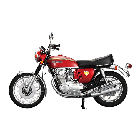
  9. De Agostini MODEL SPACE Honda CB750 FOUR User manual

De Agostini MODEL SPACE Honda CB750 FOUR User manual

01
BUILD YOUR OWN
Pack 18
TM
CONTENTS
Assembly Guide
Stage 57: The rear fender and battery box
Stage 58: The centre stand
Stage 59: The exhausts
275
Editorial and design by Continuo Creative, 39-41 North Road, London N7 9DP.
Published in the UK by De Agostini UK Ltd, Battersea Studios 2,
82 Silverthorne Road, London SW8 3HE.
Published in the USA by De Agostini Publishing USA, Inc., 915 Broadway,
Suite 609, New York, NY 10010.
All rights reserved © 2015
Warning: Not suitable for children under the age of 14. is product is not a toy
and is not designed or intended for use in play. Items may vary from those shown.
TM
www.model-space.com
275
Honda CB750 FOUR: Assembly Guide
Stage 57
Rear frame joint
Exhaust joints × 4
Screw (type R)
Screw (type W)
Joint E
Joint B
4 × 9mm screws with washers × 4
Base frame 2
The rear fender
and battery box
Phillips screwdriver
Pliers
Tweezers
Cross wrench
Multi-purpose adhesive
Screw (type E) (Stage 32)
Screw (type G) (Stage 34)
Wire holder × 3 (Stage 34)
Screws (type E) × 2 (Stage 50)
Screw (type Q) (Stage 50)
Battery box (Stage 53)
Main frame assembly (Stage 55)
Rear fender (Stage 56)
Prepare the main frame assembly from
Stage 55 and undo the nut at the end of
the pivot shaft.
Remove the left frame half from
the assembly.
Remove the centre stand, the chain
cover, the pivot shaft and the battery
box cover, then remove the drive chain
from the wheel and disconnect the rear
brake rod. Now remove the swingarm
and rear wheel from the frame. Pass the battery box cable through the
hole (circled) in the right frame half.
Tools Prepare
Your parts
1
2
3
4
276
Honda CB750 FOUR: Assembly Guide
Take the cables from the IR sensor, the
rear brake and the kick starter, and
position them in the same hole as the
battery box cable.
Hold the battery box as shown, with the
three circled tabs facing towards you.
Prepare the rear frame joint and place
one of the holes over the projection in
front of the indicator on the right frame
half. Remove any masking tape holding
the indicator wires in place.
Take the type E screw that you removed
in Stage 50, and tighten it back into the
hole in the left frame half.
Now tighten a type E screw into the hole
below the battery box.
Gently pull the battery box cable
through the hole, while tting the three
tabs into the three corresponding holes
in the right frame half.
Re-t the centre stand, then hold the
rear frame joint in position and place the
left frame half back onto the right half.
Align the two frame halves, taking
care not to trap any of the cables
between them.
5
6
7
8
9
10
11
12
277
Honda CB750 FOUR: Assembly Guide
Tighten the type E screw from Stage 32
into the hole at the front of the left frame
half, to join the front ends of the two
frame halves.
Insert the rear fender (Stage 56) between
the two frame halves and below the rear
frame joint.
Hold the rear fender in place and turn
the assembly over. Tighten a type G
screw (from Stage 34) into the hole in
the left frame half to secure the fender.
Use pliers to nish tightening the type Q
screw fully.
Reinsert the type Q screw, removed in
Stage 50, into the hole in the left frame
half to secure it to the engine.
Position the tail light and rear indicator
cables as shown.
Place the indicator cables into the two
circled grooves of the frame.
When tightening the type Q screw, you
may nd that the cross wrench hits the
transmission case cover. Temporarily
remove the cover to make tightening
the screw easier, and then re-t it.
13
14
15
16
17
18
19
20
278
Honda CB750 FOUR: Assembly Guide
Apply a small amount of multi-purpose adhesive
around the holes of the holders to secure them to
the fender.
Hold the cables in position and then place a wire
holder (Stage 34) over them, inserting the projections
(circled) on the underside of the rear fender into the
holes in the holder.
Pass the connectors of the three cables through the
arrowed hole in the side of the fender, one at a time.
Work along the rear fender, tting two more wire
holders to the fender.
21 22
23 24
279
Honda CB750 FOUR: Assembly Guide
Gently pull the three cables through the hole as far as
they will go.
Pull the three cables through the frame, just behind
the air lter.
Pass the three cables through the hole above
the air lter.
25 26
27 Stage complete
280
Honda CB750 FOUR: Assembly Guide
Base frame 6
Dynamo cover
Screws (type M) × 4
Joint E
4 × 9mm screws with washers × 4
The centre stand
Phillips screwdriver
Pliers
Cutters
2.3mm tap/tap holder
Main frame assembly (Stage 57)
Screw (type E) (Stage 37)
Battery box cover (Stage 57)
Take the main frame assembly and
turn it over. Remove the masking tape
holding the centre stand spring.
Prepare a type E screw and insert it into the circled hole on the frame.
To make the following steps easier,
it is best to remove the spring from
the stand.
Stage 58
Tools Prepare
Your parts
1
2
3
281
Honda CB750 FOUR: Assembly Guide
Pass a type E screw into the looped end
of the spring.
Use the type E screw to tap the hole,
screwing it in for about two thirds
of its thread length, then remove it.
Alternatively, use a 2.3mm tap (right).
Hold the spring next to the frame, as
shown, and tighten the type E screw into
the hole until the spring can’t move.
The centre stand spring should now look like this, and be
secured to the frame and the stand (both circled).
Hold the hooked end of the spring with pliers and pull it
up to the hole in the side of the centre stand.
Insert the tip of the hook into the hole in the centre
stand, and pass it through.
4 5 6
7
8
9
282
Honda CB750 FOUR: Assembly Guide
If the stand doesn’t operate properly,
try tightening and loosening the type E
screw until it does.
Pivot the stand forward until it’s at about
a right angle to the frame. Then let it
go, and it should spring back into the
position of the previous step.
Hold the stand down so that it’s in line
with the bottom of the frame. This is
where it will be positioned when the
model is complete.
Take the battery box cover and remove
a 3 × 3mm section from the tab at the
front with cutters, as shown above and
in Step 14.
Re-t the screw to secure the cover temporarily in place.This is the section that should be removed, so that the
tab doesn’t interfere with the battery box wire.
Place the battery box cover back into position.
3mm
3mm
10
16
11 12 13
14
15
283
Honda CB750 FOUR: Assembly Guide
Tighten the type M screw into place.
Tighten another type M screw into the lower right hole
of the cover.
Take the dynamo cover and place it into the circular
recess in the side of the transmission case cover.
Finally, tighten a type M screw into the lower left hole.
Take a type M screw and insert it into the hole at the
top of the dynamo cover.
17
18
19
20
21
Stage complete
284
Honda CB750 FOUR: Assembly Guide
Base frame 4
Control board
Screws (type G) × 5
Joint C
4 × 9mm screws with washers × 4
The exhausts
Phillips screwdriver Multi-purpose adhesive
Left exhaust assembly (Stage 17)
Right exhaust assembly (Stage 21)
Exhaust pipe joints × 4 (Stage 57)
Screws (type J) × 2 (Stage 49)
Main frame assembly (Stage 58)
STEP
1
Insert a type J screw (Stage 49) into the
circled hole in the centre of one of the
exhaust assemblies.
Prepare the exhaust
assemblies from Stages
17 and 21.
Left exhaust assembly
Right exhaust assembly
Tap the hole with the type J screw.
Stage 59
Tools Prepare
Your parts
1
2
3
285
Honda CB750 FOUR: Assembly Guide
Apply multi-purpose adhesive to the two pins on one of
the exhaust pipe joints (Stage 57).
Turn the main frame assembly over, and align the two
pins on the exhaust pipe joint with the indicated holes in
the exhaust port on the front of the engine, as shown.
Remove the screw from the tapped hole (circled),
and then tap the corresponding hole in the other
exhaust assembly.
Push the exhaust pipe joint fully into place. Hold the right exhaust assembly over the right-hand
side of the frame and engine, as shown.
Repeat Steps 5 to 7 to t the other three exhaust pipe
joints to the remaining ports.
4
9
5
6
7
8
286
Honda CB750 FOUR: Assembly Guide
Take the left exhaust assembly and insert the ends into
the exhaust pipe joints.
Insert a type J screw into the aligned holes.
Align the central section of the silencers with the circled
area of the frame.
Hold the silencers in position, and tighten the type J
screw into place.
Insert the pin into the hole, and align the adjacent
holes of the silencers and the frame.
Pin
Holes
Insert the exhaust pipes into the two right-hand
exhaust pipe joints.
10
11
12
13
14
15
287
Honda CB750 FOUR: Assembly Guide
Position the two exhaust pipes on either side of the
frame at the circled point.
Insert a type J screw into the aligned holes of the
silencers and the frame, as in Steps 13 and 14.
Tighten the type J screw into place while holding the
silencers in position.
Insert the pin into the hole and align the holes of the
silencers and the frame, as in Step 12.
16 17 18
19
Stage complete
20
Honda CB750 FOUR:
TM

Other manuals for MODEL SPACE Honda CB750 FOUR

7

Other De Agostini Toy manuals

De Agostini Model Space H.M.S. Bounty Admiralty User manual

De Agostini

De Agostini Model Space H.M.S. Bounty Admiralty User manual

De Agostini Model Space D51 200 User manual

De Agostini

De Agostini Model Space D51 200 User manual

De Agostini Model Space MiG-29 User manual

De Agostini

De Agostini Model Space MiG-29 User manual

De Agostini Model Space D51 200 User manual

De Agostini

De Agostini Model Space D51 200 User manual

De Agostini Model Space ROBI Pack 03 Instruction Manual

De Agostini

De Agostini Model Space ROBI Pack 03 Instruction Manual

De Agostini MODEL SPACE Honda CB750 FOUR User manual

De Agostini

De Agostini MODEL SPACE Honda CB750 FOUR User manual

De Agostini Model Space SANTISIMA TRINIDAD User manual

De Agostini

De Agostini Model Space SANTISIMA TRINIDAD User manual

De Agostini Model Space MiG-29 User manual

De Agostini

De Agostini Model Space MiG-29 User manual

De Agostini Model Space T-72 User manual

De Agostini

De Agostini Model Space T-72 User manual

De Agostini MODEL SPACE Soleil Royal User manual

De Agostini

De Agostini MODEL SPACE Soleil Royal User manual

De Agostini MODEL SPACE Honda CB750 FOUR User manual

De Agostini

De Agostini MODEL SPACE Honda CB750 FOUR User manual

De Agostini Model Space T-72 User manual

De Agostini

De Agostini Model Space T-72 User manual

De Agostini Model Space HUMMER H1 User manual

De Agostini

De Agostini Model Space HUMMER H1 User manual

De Agostini Model Space MiG-29 User manual

De Agostini

De Agostini Model Space MiG-29 User manual

De Agostini Model Space T-72 User manual

De Agostini

De Agostini Model Space T-72 User manual

De Agostini Model Space MiG-29 User manual

De Agostini

De Agostini Model Space MiG-29 User manual

De Agostini MODEL SPACE Honda CB750 FOUR User manual

De Agostini

De Agostini MODEL SPACE Honda CB750 FOUR User manual

De Agostini MODEL SPACE Honda CB750 FOUR User manual

De Agostini

De Agostini MODEL SPACE Honda CB750 FOUR User manual

De Agostini Model Space IJN Akagi User manual

De Agostini

De Agostini Model Space IJN Akagi User manual

De Agostini Model Space MiG-29 User manual

De Agostini

De Agostini Model Space MiG-29 User manual

De Agostini Model Space T-72 User manual

De Agostini

De Agostini Model Space T-72 User manual

De Agostini Model Space MiG-29 User manual

De Agostini

De Agostini Model Space MiG-29 User manual

De Agostini MODEL SPACE Honda CB750 FOUR User manual

De Agostini

De Agostini MODEL SPACE Honda CB750 FOUR User manual

De Agostini MODEL SPACE Honda CB750 FOUR User manual

De Agostini

De Agostini MODEL SPACE Honda CB750 FOUR User manual

Popular Toy manuals by other brands

Sebart KatanaS 30E Assembly manual

Sebart

Sebart KatanaS 30E Assembly manual

J. Perkins TWISTER BELL 47 manual

J. Perkins

J. Perkins TWISTER BELL 47 manual

Tinkerbots Robotics set manual

Tinkerbots

Tinkerbots Robotics set manual

Modeltech Simply Magic Instructions for final assembly

Modeltech

Modeltech Simply Magic Instructions for final assembly

Air Hogs Sharpshooter Quickdraw Instruction guide

Air Hogs

Air Hogs Sharpshooter Quickdraw Instruction guide

Spinmaster NINJABOTS manual

Spinmaster

Spinmaster NINJABOTS manual

Aeronaut Rambotator manual

Aeronaut

Aeronaut Rambotator manual

OMPHOBBY M2 instruction manual

OMPHOBBY

OMPHOBBY M2 instruction manual

Aeronaut Triple Neo Series manual

Aeronaut

Aeronaut Triple Neo Series manual

Step 2 Big Builders Pro Workshop manual

Step 2

Step 2 Big Builders Pro Workshop manual

KNEX Dune Buggy manual

KNEX

KNEX Dune Buggy manual

Air Hogs Mission Alpha instruction manual

Air Hogs

Air Hogs Mission Alpha instruction manual

LaserPegs Speed record PB216OB Assembly instruction

LaserPegs

LaserPegs Speed record PB216OB Assembly instruction

V-tech Grow Along Bounce & Go Pony instruction manual

V-tech

V-tech Grow Along Bounce & Go Pony instruction manual

V-tech Twist & Teach Animal Cube instruction manual

V-tech

V-tech Twist & Teach Animal Cube instruction manual

V-tech Talking Whiz Kid Power Mouse user manual

V-tech

V-tech Talking Whiz Kid Power Mouse user manual

BushBaby nestegg instructions

BushBaby

BushBaby nestegg instructions

UJ Toys Chinook 821 Using instruction

UJ Toys

UJ Toys Chinook 821 Using instruction

manuals.online logo
manuals.online logoBrands
  • About & Mission
  • Contact us
  • Privacy Policy
  • Terms and Conditions

Copyright 2025 Manuals.Online. All Rights Reserved.